Load box using self-service in-cylinder grouting jack
Technical Field
The utility model relates to a load box that uses among foundation pile self-balancing static test, especially an inside load box who uses a plurality of jacks.
Background
In the foundation pile self-balancing static test, the load box is generally only provided with one liquid injection pipe, so that after the test, liquid which is never solidified is filled between a cylinder body and a piston of the load box body, and after the foundation pile self-balancing static test, the pile generates liquid in the load box cylinder and is extruded out to generate displacement under the vertical compression state of the engineering.
Although the existing load box can realize liquid drainage and grouting through two pipes, the two pipes are at the same elevation of the side edge of the upper end of the cylinder body, so that during grouting, the liquid above the elevation of the liquid outlet can only be extruded and discharged, and the liquid below the elevation of the liquid outlet cannot be discharged completely, so that the injected slurry is diluted by the retained liquid, the concentration of the slurry is reduced, the final setting strength of the slurry is seriously reduced, and the reinforcing requirement cannot be met.
Disclosure of Invention
The utility model aims at solving the problem that exists among the prior art, provide one kind and guarantee the slurry quality when realizing the slip casting, improve the load box of the self-service jar slip casting jack of having used of filling rate.
In order to achieve the above purpose, the utility model adopts the following technical scheme: a load box using a self-service in-cylinder grouting jack comprises an upper plate, a lower plate and a hydraulic device, wherein the hydraulic device comprises a liquid inlet pipe, a liquid outlet pipe, a cylinder body and a piston, a cavity is formed in the cylinder body, and the axial direction of the cavity is consistent with the axial direction of the cylinder body; the piston is in clearance fit with the cavity, the bottom surface of the piston is partially contacted with the bottom surface of the cavity, so that a solution cavity is formed, a through hole I and a through hole II which are communicated with the solution cavity are formed in the piston, the top of the through hole I is communicated with the liquid inlet pipe, the top of the through hole II is communicated with the liquid outlet pipe, a pipe groove, an elastic part and a hollow long pipe are designed in the through hole II, one end of the elastic part is fixed with the top of the pipe groove, the other end of the elastic part is fixedly connected with the hollow long pipe, the hollow long pipe extends out of the through hole II, and a plurality of; the hydraulic devices are multiple, the adjacent liquid inlet pipe and the liquid outlet pipe are connected in series through a connecting pipe, and the upper plate and the lower plate move together with the piston and the cylinder body.
The anti-pulling lock structure is used for limiting the piston in the cylinder body when the piston moves upwards and comprises an anti-pulling lock head and an anti-pulling lock groove which are matched with each other, the anti-pulling lock head is arranged at the upper part of the cylinder body, and the head end of the anti-pulling lock head faces the side wall of the piston; the anti-pulling lock groove is arranged at the lower part of the piston, and the opening end of the anti-pulling lock groove faces the inner wall of the cylinder body.
Preferably, the anti-pulling lock head comprises a lock head, a spring and a base which are connected in sequence, the lock head is limited in the through hole by a piston, the base is fixed with the cylinder body, and the spring is compressed between the lock head and the base.
Preferably, the anti-pulling lock structures are at least two and are oppositely arranged.
Preferably, a sealing groove is formed in the side wall of the piston and used for placing the sealing ring, and the sealing groove is located below the anti-pulling locking groove.
The device comprises a cylinder, a pressure limiting explosive grouting device and a reversing pipe, wherein the pressure limiting explosive grouting device comprises two vertical grouting pipes outside the cylinder and a reversing pipe, the two vertical grouting pipes are used for grouting outside the cylinder and protecting sleeves for lower displacement wires, the lower displacement wires are fixed in the vertical grouting pipes outside the cylinder, two ends of the reversing pipe are respectively inserted into the vertical grouting pipes outside the cylinder, and the horizontal part of the reversing pipe is fixed with a lower plate.
Preferably, a pressure relief valve is arranged in the reversing pipe and comprises a pressure relief channel, a solid pressure limiting sheet and a hollow screw, the solid pressure limiting sheet is arranged between the pressure relief channel and the hollow screw, and the pressure limiting value of the solid pressure limiting sheet is smaller than the pressure bearing value of the reversing pipe.
Preferably, a pressure release valve is arranged on the side wall of the cylinder body and comprises a pressure release channel, a solid pressure limiting sheet and a hollow screw, an opening of the pressure release channel is formed in the inner wall of the cylinder body, and the solid pressure limiting sheet is arranged between the pressure release channel and the hollow screw.
Preferably, the upper plate is of a rigid lattice structure.
Preferably, an H-shaped waterproof connecting guard plate is installed between the upper plate and the lower plate, a rigid side plate of the upper plate is inserted into an upper portion thereof and fixed, and a rigid side plate of the lower plate is inserted into a lower portion thereof.
Preferably, the H-shaped waterproof connecting guard plate is made of a flexible waterproof material.
Preferably, the upper part of the hollow long pipe is provided with a sealing ring groove around the circumference thereof for placing a sealing ring.
Compared with the prior art, the utility model has the advantages of as follows:
1. design tube seat, elastic component and hollow long tube in the II interior designs of through-hole, have ensured the interior cavity of cylinder body before the slip casting for the slip casting body of slip casting in the cylinder body is high-purity neat thick liquid, has guaranteed the slurry quality, has improved the filling rate.
2. The anti-pulling lock structure not only ensures that the piston is limited in the cylinder body during movement, but also effectively transfers the anti-pulling force to the lower reinforcement cage through the anti-pulling lock when the upper reinforcement cage of the load box is subjected to upward pulling force, thereby ensuring that the engineering pile meets the anti-pulling design requirements after the self-balancing static load test pile of the foundation pile.
3. The pressure-limiting explosive grouting device is arranged to fill gaps among the cylinder bodies, so that the strength and integrity of the pile body of the foundation pile are guaranteed, and the upper load of the load box is effectively transmitted to the lower pile body of the load box.
4. The H-shaped waterproof connecting guard plate enables a periphery of the side of the whole load box to be sealed, so that after self-balancing detection of the foundation pile is achieved, displacement caused by loading of a piston in a cylinder body in the load box is avoided, underground water around the pile permeates the outside of the wrapping cylinder, and high-purity clean slurry is poured into slurry outside the cylinder.
5. The upper plate of the load box adopts a rigid lattice structure to replace a steel plate, so that pipelines for connecting the load boxes can be laid conveniently; after the concrete is poured, the lattice components and the concrete are combined to form the high-strength stiff concrete slab.
6. A plurality of cylinder bodies are connected in series through connecting pipes at the tops of the cylinder bodies, and the whole liquid feeding, liquid discharging and grouting of the load box can be realized.
Drawings
Fig. 1 is a schematic structural view of embodiment 1 of the present invention;
FIG. 2 is a schematic diagram of the hydraulic apparatus of FIG. 1;
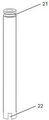
FIG. 3 is a schematic view of the hollow long tube shown in FIG. 1;
FIG. 4 is a schematic view of the anti-pulling lock head shown in FIG. 1;
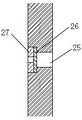
FIG. 5 is a schematic diagram of the relief valve of FIG. 1;
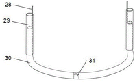
FIG. 6 is a schematic structural view of the pressure-limiting explosive grouting device in FIG. 1;
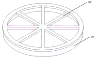
FIG. 7 is a schematic diagram of the upper plate structure of FIG. 1;
FIG. 8 is a schematic view of the structure of the lower plate of FIG. 1;
FIG. 9 is a schematic view of a portion of the structure of FIG. 1;
FIG. 10 is a schematic view of the hydraulic apparatus of FIG. 1 in a start-stop state;
in fig. 1, a hydraulic device; 2. an upper plate; 3. waterproof connecting guard plates; 4. a lower plate; 5, connecting the pipes; 6. a pressure-limiting explosive grouting device;
in FIG. 2, 7, a liquid inlet pipe; 8. a liquid outlet pipe; 9. a bolt is fixed above the bracket; 10. a lower fixing bolt; 11. a cylinder body; 12. a piston; 13. a pipe groove; 14. a spring; 15. a seal ring; 16. a hollow long tube; 17. an anti-pulling lock head; 18. a pressure relief valve; 19. an anti-pulling lock groove; 20. a sealing groove and a sealing ring;
in fig. 3, 21, seal ring groove; 22. an opening;
in fig. 4, 23, a lock head; 24. a spring; 25. a base;
in fig. 5, 26, the pressure relief channel; 27. a solid pressure limiting sheet; 28. a hollow screw;
in fig. 6, 34, lower displacement wires; 35. the lower displacement wire sheath is also used as an external grouting vertical conduit; 36. a reversing tube; 18. a pressure relief valve;
in fig. 7, 30, the frame and the lattice beam; 31. an upper rigid side panel;
in fig. 8, 32, bottom plate; 33. a lower rigid side panel.
Detailed Description
It should be noted that, in the following embodiments of the present invention, all the directional terms are described according to the drawings, and do not constitute a limitation of the present invention.
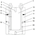
The present invention will be described in further detail with reference to the accompanying drawings 1-10: a load box using a self-service in-cylinder grouting jack is shown in figure 1 and comprises a hydraulic device 1, an upper plate 2, a waterproof connecting guard plate 3, a lower plate 4, a connecting pipe 5 and a pressure-limiting explosive grouting device 6; the hydraulic device 1 is arranged between the upper plate 2 and the lower plate 3, is provided with a plurality of hydraulic devices, and is connected in series through a connecting pipe 5; the upper plate 2 is of a rigid lattice structure, the waterproof connecting guard plate 3 is made of flexible materials and is movably connected with the upper plate 2 and the lower plate 4, and the pressure-limiting explosive grouting device 6 is installed on the lower plate 4.
As shown in fig. 2-3, the hydraulic device 1 comprises a liquid inlet pipe 7, a liquid outlet pipe 8, a cylinder 11 and a piston 12, wherein the bottom of the cylinder 11 is fixed with a lower plate 4 through a lower fixing bolt 10, the interior of the cylinder is a cavity, and the axial direction of the cavity is consistent with the axial direction of the cylinder 11; a piston 12 is fixed with the upper plate 2 through an upper fixing bolt 9, inserted into the cavity, in clearance fit with the cavity, and the bottom surface of the piston is partially contacted with the bottom surface of the cavity, so that a solution cavity is formed, a liquid inlet hole and a liquid outlet hole which are axially consistent with the cylinder 11 are formed in the piston, the liquid inlet hole and the liquid outlet hole are communicated with the solution cavity, the top of the liquid inlet hole is communicated with a liquid inlet pipe 7, and the top of the liquid outlet hole is communicated with a liquid outlet pipe 8; a pipe groove 13, a spring 14 and a hollow long pipe 16 are designed in the liquid outlet hole, the axial direction of the pipe groove 13 is consistent with the axial direction of the liquid outlet hole, the radial dimension of the pipe groove is slightly larger than that of the liquid outlet hole, the top of the pipe groove is positioned in the liquid outlet hole and is in a step shape, the bottom of the pipe groove is flush with the bottom of the liquid outlet hole, the top of the spring 14 is fixedly connected with the top of the pipe groove, the bottom of the spring is fixedly connected with the top of the hollow long pipe 16, and; the bottom of the hollow long pipe 16 extends out of the liquid outlet hole and is tightly attached to the bottom of the solution cavity, the hollow long pipe is communicated with the solution cavity through a plurality of openings 22 formed in the bottom of the hollow long pipe, when a pressurizing air pump is used for supplying air and pressurizing from the liquid inlet pipe 7, liquid in the cylinder body 11 is pressed into the hollow long pipe from the opening of the hollow long pipe 16 by air pressure and is discharged through the hollow long pipe, the cavity in the cylinder body 11 before grouting is ensured, and then the grouting body in the cylinder body is high-purity clean slurry; because a gap exists between the hollow long pipe 16 and the pipe groove 13, in order to ensure complete liquid discharge, a sealing ring groove 21 is arranged on the upper part of the hollow long pipe 16 around the axis of the hollow long pipe for installing a sealing ring 15 to ensure the sealing between the hollow long pipe 16 and the liquid discharge hole.
In order to ensure that the piston 12 is limited in the cylinder 11 when moving and simultaneously to ensure that the load box effectively transmits the uplift force to the lower steel reinforcement cage when the upper steel reinforcement cage bears the uplift force, thereby ensuring that the engineering pile meets the design requirement of uplift after the foundation pile self-balancing static load test pile, an uplift lock device is additionally arranged between the piston and the cylinder, as shown in fig. 2 and 4, the uplift lock device comprises an uplift lock head 17 and an uplift lock groove 19 which are matched with each other, the uplift lock head 17 is arranged at the upper part of the cylinder 11 and comprises a lock head 23, a spring 24 and a base 25 which are sequentially connected, the head end of the lock head 23 is arc-shaped and faces the outer wall of the piston 12, the spring 24 is compressed between the lock head 23 and the base 25, the base is fixed with the cylinder 11, and the uplift lock groove 19 is arranged at the lower part of the piston. When the piston 12 moves upwards to the position opposite to the anti-pulling lock head 17 and the anti-pulling lock groove 19, the lock head 23 is bounced into the anti-pulling lock groove 19 under the action of the spring 24, so that the piston and the cylinder are locked and do not move mutually any more. In order to make the anti-pulling effect better, the anti-pulling lock devices are designed into two parts and are oppositely arranged in the two side walls of the cylinder body 11; of course, the number of the anti-pulling lock structures is not limited to two, and can be multiple, and the anti-pulling lock structures are generally designed according to anti-pulling requirements (assuming that the anti-pulling capacity of each anti-pulling lock is a, and the overall anti-pulling requirement is b, the number n is more than or equal to b/a).
As shown in fig. 2, since there is a gap between the piston 12 and the cylinder 11, in order that water or slurry will not leak from the gap during the loading process, a sealing groove and a sealing ring 20 are provided at opposite sides of the piston 12 to ensure the sealing effect thereof, and the sealing groove is located below the anti-pulling locking groove 19.
In order to enable the reinforced load box and the engineering pile to form a continuous whole, ensure the strength and integrity of a pile body of the foundation pile, effectively transmit the upper load of the load box to the lower pile body of the load box, and increase a pressure-limiting explosive grouting device, as shown in fig. 5-6, the pressure-limiting explosive grouting device 6 comprises a lower displacement wire 34, a lower displacement wire sheath and outer grouting vertical conduit 35, a reversing conduit 36 and a pressure release valve 18, wherein the lower displacement wire 34 is fixed in the lower displacement wire sheath and outer grouting vertical conduit 35; the lower displacement wire sheath and the outer grouting vertical conduit 35 are two and are respectivelyThe vertical grouting pipe is arranged at the two ends of the reversing pipe 36, and the vertical grouting pipe outside the cylinder and the protecting sleeve of the lower displacement wire are integrated into a multifunctional pipe, so that the lower displacement wire 34 can be prevented from being held by concrete, and the multifunctional pipe can be used as a vertical conduit for grouting outside the cylinder; two ends of the reversing pipe 36 are respectively inserted into the lower displacement wire sheath and outer grouting vertical conduit 35, and the horizontal part of the reversing pipe is welded and fixed with the lower plate 4, so that the functions of drainage and direction changing are achieved; meanwhile, the free ends of the lower displacement wire sheath, the outer grouting vertical conduit 35 and the reversing pipe 36 extend out of the upper plate 2, and the length L of the vertical part of the reversing pipe 36 is larger than the displacement value of the piston 12 under the test termination condition of the self-balancing static load test pile; the pressure relief valve 18 is arranged in the reversing pipe 36 and comprises a pressure relief channel 26, a solid pressure limiting sheet 27 and a hollow screw 28, wherein the solid pressure limiting sheet 27 is arranged between the pressure relief channel 26 and the hollow screw 28, and the pressure limiting value P of the solid pressure limiting sheet 27 isaLess than the bearing capacity P of the reversing tube 36bWhen the loaded pressure value is in Pa、PbIn the middle, the slurry breaks through the solid pressure limiting plate 27, the hollow screw 28 releases the pressure, and the slurry fills the gap between the lower plate 4 and the waterproof connecting protection plate 3. In order to fill the gaps between the hydraulic devices with slurry, as shown in fig. 2, a pressure relief valve 18 is additionally arranged on the side wall of the cylinder body 11, wherein the pressure relief valve 18 has the same structure as that of the pressure limiting explosive grouting device, the opening of a pressure relief channel 26 is arranged on the inner wall of the cylinder body 11, and a solid pressure limiting sheet 27 is arranged between the pressure relief channel and a hollow screw 28.
As shown in fig. 7-9, the upper plate 2 is a rigid lattice structure, and includes a frame and lattice beam 30, and an upper rigid side plate 31, the frame and lattice beam 30 is an upper surface of the upper plate, and the upper rigid side plate 31 is disposed around the frame and lattice beam 30. As shown in fig. 8, the lower plate 4 includes a bottom plate 32 and a lower rigid side plate 33, the bottom plate 32 is a rigid plate and has a hollow center, i.e. the bottom plate 32 is ring-shaped, the lower rigid side plate 33 is disposed around the bottom plate 32, the upper plate 2 and the lower plate 4 are connected together by a waterproof connecting guard plate 3, the waterproof connecting guard plate 3 is H-shaped and made of flexible waterproof material, and has a plurality of vent holes so that the upper rigid side plate 31 and the lower rigid side plate 33 can be inserted into the vent holes, the upper portion of the H-shape encloses and fixes the upper rigid side plate 31 of the upper plate 2, and the lower portion of the H-shape encloses the. When the load tank is filled with liquid and pressurized, the lower rigid side plate 33 of the lower plate 4 is gradually withdrawn with the piston 12 of the hydraulic device 1.
As shown in figure 10, water is injected into the cavity through the liquid inlet pipe 7, the cylinder 11 moves downwards relative to the piston 12 along with the increase of the water amount, the spring 14 presses the long hollow pipe 16 to enable the bottom of the long hollow pipe to be always attached to the bottom of the cylinder, and when the anti-pulling lock groove 19 moves to be opposite to the anti-pulling lock head 17, the anti-pulling lock head 17 pops up to lock the piston 12 and the cylinder 11, so that relative movement does not occur any more.
The implementation steps are as follows:
liquid injection and pressurization: when liquid injection and pressurization are carried out, the liquid outlet pipe 8 is sealed and injected from the liquid inlet pipe 7;
1. when not pressurized, the piston is in the initial position, the spring is pressurized, and the pressure value P1= P2= P3= P4, as shown in a diagram in FIG. 10;
2. pressurizing, sealing the liquid outlet pipe 8, and pressurizing from the liquid feeding pipe 7; the spring always supports the hollow long pipe to enable the hollow long pipe to be tightly attached to the bottom of the cylinder body, and the pressure value is more than P1 and more than P2 and more than P3 and more than P4;
3. the liquid injection and pressurization are continued, when the anti-pulling lock groove 19 on the piston 12 reaches the position of the anti-pulling lock head 17, the anti-pulling lock head 17 is ejected, the dead lock piston can not move any more, and when the end condition is reached, the pressure value P1= P2= P3= P4, as shown in a diagram b in FIG. 10;
(II) inflation and drainage: after the liquid injection is finished, the inflation and liquid drainage are started, and when the inflation and liquid drainage are carried out, the liquid inlet pipe 7 and the liquid outlet pipe 8 are not closed;
4. and (3) starting inflation and drainage: gas is injected from the liquid inlet pipe 7, the gas is filled into the cylinder body 11 from top to bottom, the extrusion liquid is discharged from the liquid outlet pipe 8, and the pressure value P1 is more than P2 is more than P3 is more than P4;
5. continuing to inflate until the liquid outlet pipe 8 does not discharge liquid any more, indicating that the liquid in the cylinder body is drained, stopping inflating, and stopping inflating until a pressure value P1= P2= P3= P4;
(III) grouting: when the liquid outlet pipe 8 does not discharge liquid any more, grouting is started;
6. and (3) starting grouting: injecting from the liquid inlet pipe 7, wherein the pressure value is P1 > P2 > P3 > P4;
7. grouting is continued until the slurry overflows from the liquid outlet pipe, and the grouting is stopped until the pressure value is P1= P2= P3= P4;
(IV) grouting in pressure-limiting explosive grouting device
8. After closing the lower displacement wire sheath at one end and the outer grouting vertical conduit, continuously grouting until slurry overflows from the conduit at the other side, and sampling;
9. after sampling, the overflow end is closed, and then the slurry is injected into the pressure relief valve from the inlet end at high pressure until the pressure relief valve is detonated, so that the slurry is forced to naturally flow to and fill gaps at any phase.
In this example, water was used as the loading liquid, and the affinity to the slurry was better and the cost was lower than oil.
The above embodiment is only a preferred embodiment of the present invention, and does not limit the present invention. The anti-pulling lock device can be arranged in any load box structure utilizing the principle of a jack, the pressure-limiting and explosive grouting device and the anti-pulling lock device can be arranged in the same implementation mode at the same time, and can also be arranged in different implementation modes separately, namely, the pressure-limiting and explosive grouting device is suitable for any load box structure. Any extension, deformation and the like of the ordinary skilled in the art without departing from the working principle of the present invention shall be included in the protection scope of the present invention.