CN212577053U - Powder concentrator pipeline cleaning device is used in fly ash production - Google Patents
Powder concentrator pipeline cleaning device is used in fly ash production Download PDFInfo
- Publication number
- CN212577053U CN212577053U CN202020903656.5U CN202020903656U CN212577053U CN 212577053 U CN212577053 U CN 212577053U CN 202020903656 U CN202020903656 U CN 202020903656U CN 212577053 U CN212577053 U CN 212577053U
- Authority
- CN
- China
- Prior art keywords
- pipe
- water
- water tank
- communicated
- discharging pipe
- Prior art date
- Legal status (The legal status is an assumption and is not a legal conclusion. Google has not performed a legal analysis and makes no representation as to the accuracy of the status listed.)
- Expired - Fee Related
Links
Images


Abstract
The utility model discloses a fly ash production is with selection powder machine pipeline cleaning device, including water tank and discharging pipe, one side of discharging pipe is located to the water tank, the bottom side-mounting of discharging pipe has the valve, be equipped with the circulation mechanism that is used for the circulation to wash water between water tank and the discharging pipe, circulation mechanism includes first water pump and second water pump, top in the water tank is installed to first water pump, the second water pump is installed in the bottom in the water tank, there is the filter screen on the inside well upper portion of water tank through slide rail horizontally connect, the outside of discharging pipe is equipped with the stoving mechanism that is used for drying to discharging pipe inside. The utility model discloses accelerate stoving speed, avoid drying naturally, drying efficiency is high, water resource reuse, the water economy resource need not the manual work and dismantles the discharging pipe and get off the washing, convenient operation, labour saving and time saving.
Description
Technical Field
The utility model relates to a selection powder machine technical field especially relates to a fly ash production is with selection powder machine pipeline cleaning device.
Background
The powder concentrator is widely applied to coal mills, raw material discharge drying mills and cement mill systems in novel dry cement production lines. The powder concentrator discharges the screened fly ash through the discharge pipeline after the fly ash particles are screened, the fly ash is easily adhered to the inner wall of the discharge pipeline after the discharge pipeline works for a long time, and the fly ash needs to be cleaned regularly.
The existing powder concentrator pipeline is manually disassembled to be cleaned when most of the pipeline of the powder concentrator is cleaned, and the operation is troublesome; the part adopts cleaning device to clear up, but current selection powder machine pipeline cleaning device lacks the stoving step after finishing the clearance, and the pipeline dries naturally for a long time, inefficiency, and washs the unable reuse of water, extravagant water resource.
An effective solution to the problems in the related art has not been proposed yet.
SUMMERY OF THE UTILITY MODEL
The utility model aims at solving the defects existing in the prior art and providing a powder concentrator pipeline cleaning device for fly ash production.
In order to achieve the above purpose, the utility model adopts the following technical scheme:
the utility model provides a fly ash production is with selection powder machine pipeline cleaning device, includes water tank and discharging pipe, one side of discharging pipe is located to the water tank, the bottom side-mounting of discharging pipe has the valve, be equipped with the circulation mechanism that is used for the circulation to wash water between water tank and the discharging pipe, circulation mechanism includes first water pump and second water pump, first water pump is installed at the top in the water tank, the second water pump is installed at the bottom in the water tank, the middle and upper portion of water tank inside has the filter screen through slide rail horizontally connect, the outside of discharging pipe is equipped with the stoving mechanism that is used for drying to discharging pipe inside.
Preferably, the circulating mechanism further comprises a return pipe, a water adding pipe and a water discharging pipe, the top of the second water pump is communicated with the water adding pipe, and the other end of the water adding pipe extends out of the inside of the water tank and is communicated with the side face of the discharging pipe.
Preferably, one end of the first water pump is communicated with a drain pipe, the other end of the first water pump is communicated with a return pipe, the other end of the return pipe extends out of the inside of the water tank and is communicated with the other side of the drain pipe, and a valve is arranged on the return pipe.
Preferably, the top of one side outside the water tank is connected with a side door through a hinge, a handle is welded on the side door, and a water filling port is arranged in the middle of the top of the water tank.
Preferably, stoving mechanism includes blast pipe, air heater, air intake and play tuber pipe, the air heater is installed in discharging pipe bottom one side, the air intake has been seted up to the air heater bottom, the tuber pipe has been seted up to the air heater side, go out tuber pipe other end and discharging pipe bottom one side intercommunication, discharging pipe top one side intercommunication has the blast pipe, install the valve on the blast pipe.
Preferably, the drying mechanism comprises an air outlet pipe, an air exhaust pump, an air inlet pipe and an electric heating wire, the air exhaust pump is installed on one side of the top of the discharge pipe, one end of the air exhaust pump is communicated with the air outlet pipe, the other end of the air exhaust pump is communicated with the air exhaust pipe, and the other end of the air exhaust pipe is communicated with one side of the top of the discharge pipe.
Preferably, the other side of the top of the discharge pipe is communicated with an air inlet pipe, an electric heating wire is embedded in the inner wall of the discharge pipe, and a valve is installed on the air inlet pipe.
The utility model has the advantages that:
1. the utility model discloses a stoving mechanism dries the discharging pipe after wasing for stoving speed avoids naturally drying, and drying efficiency is high.
2. The utility model discloses a water after first water pump will wash is taken out to the water tank once more in, filters the inside fly ash of water after will washing through the filter screen, and the clean water after straining gets back to the water tank bottom and carries out reuse, water economy resource.
3. The utility model discloses a water in the second water pump lets in the discharging pipe with the water tank and washs the fly ash of adhesion on the discharging pipe wall in, need not the manual work and dismantles the discharging pipe and get off the washing, convenient operation, labour saving and time saving.
Drawings
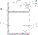
Fig. 1 is a schematic structural diagram of an embodiment 1 of a powder concentrator pipeline cleaning device for fly ash production according to the present invention;
fig. 2 is a sectional view of a water tank of the embodiment 1 of the pipe cleaning device of the powder concentrator for producing fly ash provided by the present invention;
fig. 3 is a partial sectional view of the discharging pipe of embodiment 2 of the powder concentrator pipeline cleaning device for fly ash production according to the present invention.
In the figure: 1. a water filling port; 2. a side door; 3. a water tank; 4. an exhaust pipe; 5. a return pipe; 6. a discharge pipe; 7. a valve; 8. a water feeding pipe; 9. a hot air blower; 10. an air inlet; 11. an air outlet pipe; 12. filtering with a screen; 13. a drain pipe; 14. a first water pump; 15. a second water pump; 16. an air outlet pipe; 17. an air exhaust pipe; 18. an air pump; 19. an air inlet pipe; 20. an electric heating wire.
Detailed Description
The technical solutions in the embodiments of the present invention will be described clearly and completely with reference to the accompanying drawings in the embodiments of the present invention, and it is obvious that the described embodiments are only some embodiments of the present invention, not all embodiments.
Example 1
Referring to fig. 1-2, a coal ash production is with selection powder machine pipeline cleaning device, including water tank 3 and discharging pipe 6, discharging pipe 6 is the discharge pipe of selection powder machine, one side of discharging pipe 6 is located to water tank 3, the bottom side-mounting of discharging pipe 6 has valve 7, be equipped with the circulation mechanism that is used for the circulation to wash water between water tank 3 and the discharging pipe 6, circulation mechanism includes first water pump 14 and second water pump 15, top in water tank 3 is installed to first water pump 14, second water pump 15 is installed in water tank 3 bottom, there is filter screen 12 in the inside well upper portion of water tank 3 through slide rail horizontally connect, the outside of discharging pipe 6 is equipped with the stoving mechanism that is used for drying to discharging pipe 6 inside.
In the utility model, the circulating mechanism also comprises a return pipe 5, a water feeding pipe 8 and a drain pipe 13, the top of a second water pump 15 is communicated with the water feeding pipe 8, the other end of the water feeding pipe 8 extends out of the inside of the water tank 3 and is communicated with the side surface of the discharging pipe 6, one end of a first water pump 14 is communicated with the drain pipe 13, the other end of the first water pump 14 is communicated with the return pipe 5, the other end of the return pipe 5 extends out of the inside of the water tank 3 and is communicated with the other side of the discharging pipe 6, a valve 7 is arranged on the return pipe 5, a side door 2 is connected above one side of the outside of the water tank 3 through a hinge, a handle is welded on the side door 2 and can be opened by the handle to clean the filter screen 12, the middle part of the top of the water tank 3 is provided with a water feeding port 1, the drying mechanism comprises, the other end of the air outlet pipe 11 is communicated with one side of the bottom of the discharge pipe 6, one side of the top of the discharge pipe 6 is communicated with the exhaust pipe 4, and the exhaust pipe 4 is provided with a valve 7.
The working principle of the embodiment is as follows: cleaning water is added into the water tank 3 through the water adding port 1, the second water pump 15 is started to introduce the water in the water tank 3 into the discharge pipe 6 through the water adding pipe 8 to clean the fly ash adhered to the pipe wall of the discharge pipe 6, the discharge pipe does not need to be disassembled and cleaned manually, and the operation is convenient, time and labor are saved; opening a valve 7 on a return pipe 5, starting first water, pumping the cleaned water into the water tank 3 again through the return pipe 5 by a first water pump 14, filtering fly ash in the cleaned water by a filter screen 12, and returning the filtered clean water to the bottom of the water tank 3 for recycling, so that water resources are saved; start the air heater 9 and let in hot-blastly in toward discharging pipe 6, dry discharging pipe 6 after wasing for drying speed avoids naturally drying, and drying efficiency is high.
Example 2
Referring to fig. 3, the present embodiment is different from embodiment 1 only in that the drying mechanism includes an air outlet pipe 16, an air exhaust pipe 17, an air exhaust pump 18, an air inlet pipe 19 and a heating wire 20, the air exhaust pump 18 is installed on one side of the top of the discharge pipe 6, one end of the air exhaust pump 18 is communicated with the air outlet pipe 16, the other end of the air exhaust pump 18 is communicated with the air exhaust pipe 17, the other end of the air exhaust pipe 17 is communicated with one side of the top of the discharge pipe 6, the other side of the top of the discharge pipe 6 is communicated with the air inlet pipe 19, the heating wire.
The working principle of the embodiment is as follows: the heating wire 20 is electrified to heat the air in the discharge pipe 6 to dry the cleaned discharge pipe 6, the valve 7 on the air inlet pipe 19 is opened after drying is finished, the air suction pump 18 is started to suck the dried damp and hot air to the outside, and the outside cold air enters the discharge pipe 6 from the air inlet pipe 19, so that the drying speed is increased, natural drying is avoided, and the drying efficiency is high.
Having shown and described the basic principles and essential features of the invention and advantages thereof, it will be apparent to those skilled in the art that the invention is not limited to the details of the foregoing exemplary embodiments, but is capable of other specific forms without departing from the spirit or essential characteristics thereof, and it is therefore intended that the embodiments be considered as exemplary and not limiting in any way, since the scope of the invention is defined by the appended claims rather than by the foregoing description, and all changes which come within the meaning and range of equivalency of the claims are therefore intended to be embraced therein and are therefore not to be embraced therein by any reference numerals in the claims.
Furthermore, it should be understood that although the present description refers to embodiments, not every embodiment may contain only a single embodiment, and such description is for clarity only, and those skilled in the art should integrate the description, and the embodiments may be combined as appropriate to form other embodiments understood by those skilled in the art.
Claims (7)
1. The utility model provides a fly ash production is with selection powder machine pipeline cleaning device, includes water tank (3) and discharging pipe (6), its characterized in that, one side of discharging pipe (6) is located in water tank (3), valve (7) are installed to the bottom side of discharging pipe (6), be equipped with the circulation mechanism that is used for the circulation to wash water between water tank (3) and discharging pipe (6), circulation mechanism includes first water pump (14) and second water pump (15), top in water tank (3) is installed in first water pump (14), bottom in water tank (3) is installed in second water pump (15), the well upper portion of water tank (3) inside has filter screen (12) through slide rail horizontally connect, the outside of discharging pipe (6) is equipped with the stoving mechanism that is used for drying discharging pipe (6) inside.
2. The powder concentrator pipeline cleaning device for fly ash production according to claim 1, wherein the circulating mechanism further comprises a return pipe (5), a water feeding pipe (8) and a water discharging pipe (13), the top of the second water pump (15) is communicated with the water feeding pipe (8), and the other end of the water feeding pipe (8) extends out of the inside of the water tank (3) and is communicated with the side surface of the discharging pipe (6).
3. The cleaning device for the powder concentrator pipeline for the fly ash production according to claim 2, wherein one end of the first water pump (14) is communicated with a drain pipe (13), the other end of the first water pump (14) is communicated with a return pipe (5), the other end of the return pipe (5) extends out of the water tank (3) and is communicated with the other side of the discharge pipe (6), and a valve (7) is installed on the return pipe (5).
4. The powder concentrator pipeline cleaning device for coal ash production according to claim 3, characterized in that a side door (2) is connected to the upper part of one side of the outer part of the water tank (3) through a hinge, a handle is welded on the side door (2), and a water filling port (1) is arranged in the middle of the top of the water tank (3).
5. The cleaning device for the pipeline of the powder concentrator for producing fly ash according to claim 4, wherein the drying mechanism comprises an exhaust pipe (4), a hot air blower (9), an air inlet (10) and an air outlet pipe (11), the hot air blower (9) is installed on one side of the bottom of the discharge pipe (6), the air inlet (10) is formed in the bottom of the hot air blower (9), the air outlet pipe (11) is formed in the side surface of the hot air blower (9), the other end of the air outlet pipe (11) is communicated with one side of the bottom of the discharge pipe (6), the exhaust pipe (4) is communicated with one side of the top of the discharge pipe (6), and a valve (7) is installed on the exhaust pipe (4).
6. The powder concentrator pipeline cleaning device for coal ash production according to claim 4, wherein the drying mechanism comprises an air outlet pipe (16), an air pumping pipe (17), an air pumping pump (18), an air inlet pipe (19) and an electric heating wire (20), the air pumping pump (18) is installed on one side of the top of the discharge pipe (6), one end of the air pumping pump (18) is communicated with the air outlet pipe (16), the other end of the air pumping pump (18) is communicated with the air pumping pipe (17), and the other end of the air pumping pipe (17) is communicated with one side of the top of the discharge pipe (6).
7. The powder concentrator pipeline cleaning device for coal ash production according to claim 6, wherein the other side of the top of the discharge pipe (6) is communicated with an air inlet pipe (19), an electric heating wire (20) is embedded in the inner wall of the discharge pipe (6), and a valve (7) is mounted on the air inlet pipe (19).
Priority Applications (1)
| Application Number | Priority Date | Filing Date | Title |
|---|---|---|---|
| CN202020903656.5U CN212577053U (en) | 2020-12-23 | 2020-12-23 | Powder concentrator pipeline cleaning device is used in fly ash production |
Applications Claiming Priority (1)
| Application Number | Priority Date | Filing Date | Title |
|---|---|---|---|
| CN202020903656.5U CN212577053U (en) | 2020-12-23 | 2020-12-23 | Powder concentrator pipeline cleaning device is used in fly ash production |
Publications (1)
| Publication Number | Publication Date |
|---|---|
| CN212577053U true CN212577053U (en) | 2021-02-23 |
Family
ID=74641450
Family Applications (1)
| Application Number | Title | Priority Date | Filing Date |
|---|---|---|---|
| CN202020903656.5U Expired - Fee Related CN212577053U (en) | 2020-12-23 | 2020-12-23 | Powder concentrator pipeline cleaning device is used in fly ash production |
Country Status (1)
| Country | Link |
|---|---|
| CN (1) | CN212577053U (en) |
Cited By (1)
| Publication number | Priority date | Publication date | Assignee | Title |
|---|---|---|---|---|
| CN113605392A (en) * | 2021-08-11 | 2021-11-05 | 中建八局发展建设有限公司 | Device for pumping bulk concrete in deep foundation pit and working method thereof |
-
2020
- 2020-12-23 CN CN202020903656.5U patent/CN212577053U/en not_active Expired - Fee Related
Cited By (1)
| Publication number | Priority date | Publication date | Assignee | Title |
|---|---|---|---|---|
| CN113605392A (en) * | 2021-08-11 | 2021-11-05 | 中建八局发展建设有限公司 | Device for pumping bulk concrete in deep foundation pit and working method thereof |
Similar Documents
| Publication | Publication Date | Title |
|---|---|---|
| CN109894421A (en) | A kind of hardware smallclothes cleaning drying device | |
| CN102140749A (en) | Washing machine and washing control method thereof | |
| CN211386085U (en) | Machine part belt cleaning device | |
| CN212577053U (en) | Powder concentrator pipeline cleaning device is used in fly ash production | |
| CN110653211A (en) | Multifunctional medicine washing machine | |
| CN207176304U (en) | The wash mill that a kind of water circulation uses | |
| CN113048755A (en) | Environment-friendly is meat drying-machine for food processing | |
| CN210416552U (en) | Device for quickly overhauling warm water tank of common-speed train | |
| CN214928141U (en) | Dust collector of circular screen printer | |
| CN202007332U (en) | Laundry machine | |
| CN205413732U (en) | Special cleaning machine of quick type cage box | |
| CN211112729U (en) | High-efficiency washing machine | |
| CN209849409U (en) | Solid beverage raw material cleaning device | |
| CN112414175A (en) | Hot and humid waste gas heat recovery device of feed production unit | |
| CN110653225A (en) | Water circulation device for cleaning oil cylinder | |
| CN113083401A (en) | Quick cleaning equipment of raw materials wheat in bread production | |
| CN105483835A (en) | Feather cleaning-drying integrated machine | |
| CN207805397U (en) | A kind of converted starch cleaning dust remover | |
| CN215996041U (en) | Dust removal cabinet is used in production of multi-functional mica powder | |
| CN213194965U (en) | Screen surface cleaning device of touch screen | |
| CN217797629U (en) | Oil pump cleaning device | |
| CN220781481U (en) | Cleaning device in smoke exhaust ventilator | |
| CN110029461A (en) | A kind of printing and dyeing rinsing machine with automatic cleaning strainer function | |
| CN213896303U (en) | Fishing net line cleaning and drying device | |
| CN219043522U (en) | Screening and cleaning equipment |
Legal Events
| Date | Code | Title | Description |
|---|---|---|---|
| GR01 | Patent grant | ||
| GR01 | Patent grant | ||
| CF01 | Termination of patent right due to non-payment of annual fee |
Granted publication date: 20210223 Termination date: 20211223 |
|
| CF01 | Termination of patent right due to non-payment of annual fee |