CN212553470U - Clamp with good universality - Google Patents
Clamp with good universality Download PDFInfo
- Publication number
- CN212553470U CN212553470U CN202020927775.4U CN202020927775U CN212553470U CN 212553470 U CN212553470 U CN 212553470U CN 202020927775 U CN202020927775 U CN 202020927775U CN 212553470 U CN212553470 U CN 212553470U
- Authority
- CN
- China
- Prior art keywords
- block
- bolt
- rotating
- fixedly connected
- rotating block
- Prior art date
- Legal status (The legal status is an assumption and is not a legal conclusion. Google has not performed a legal analysis and makes no representation as to the accuracy of the status listed.)
- Active
Links
Images

Landscapes
- Jigs For Machine Tools (AREA)
Abstract
The utility model discloses an anchor clamps that the commonality is good, the on-line screen storage device comprises a base, the clamp splice is decided to one side fixedly connected with on base top, the opposite side sliding connection on base top has the clamp splice of moving, the first extension board of top fixedly connected with of moving the clamp splice, the inboard rotation of first extension board is connected with first rotation piece. The utility model discloses when carrying out the centre gripping to the part, extract first bolt and second bolt, then adjust first turning block and second turning block according to the shape of part, if the part is spherical, it is corresponding with two spherical concave surfaces of first turning block and second turning block, if the part is tubular product, select to use horizontal arcwall face or vertical arcwall face to carry out the centre gripping according to the type of processing, if the part of rule, use the straight face to carry out the centre gripping, current anchor clamps compare, the utility model discloses can carry out the centre gripping to the part of multiple shape, area of contact is big, and the centre gripping is more stable, improves the precision.
Description
Technical Field
The utility model relates to an anchor clamps, anchor clamps that concretely relates to commonality is good.
Background
Machining refers to a process of changing the physical dimensions or properties of a workpiece by a mechanical device. According to the difference of the processing mode, the processing method can be divided into cutting processing and pressure processing, in the mechanical processing process, a workpiece needs to be positioned, and in the prior art, the workpiece is positioned through a positioning clamp.
The clamping face of anchor clamps among the prior art is mostly straight face, can only carry out the centre gripping to the regular part of shape, and is little to the part area of contact of other shapes, and the part drops easily after the centre gripping.
SUMMERY OF THE UTILITY MODEL
An object of the utility model is to provide an anchor clamps that the commonality is good to solve the problem that proposes in the above-mentioned background art.
In order to achieve the above object, the utility model provides a following technical scheme: the clamp with good universality comprises a base, wherein one side of the top end of the base is fixedly connected with a fixed clamping block, the other side of the top end of the base is connected with a movable clamping block in a sliding way, the top end of the movable clamping block is fixedly connected with a first support plate, the inner side of the first support plate is rotatably connected with a first rotating block, the front surface of the first support plate is rotatably connected with a first knob, the first knob and the first rotating block are in transmission connection through a first rotating rod, the top end of the fixed clamping block is fixedly connected with a second supporting block, the inner side of the second supporting block is rotatably connected with a second rotating block, the outer side of the second supporting block is rotatably connected with a second knob, the second knob is in transmission connection with the second rotating block through a second rotating rod, and four faces of the second rotating block and four faces of the first rotating block are respectively a transverse arc face, a longitudinal arc face, a straight face and a spherical concave face.
As a preferred technical scheme of the utility model, the spout has been seted up on the top of base, the inside rotation of spout is connected with the threaded rod, move the bottom fixedly connected with sliding block of clamp splice, threaded rod and sliding block threaded connection, the hand wheel of one end fixedly connected with of threaded rod.
As a preferred technical scheme of the utility model, four recesses have all been seted up to the surface of first dwang and the surface of second dwang, the second bolt has been pegged graft on the top of second piece, the top of first extension board is pegged graft and is had first bolt, the bottom of first bolt and the recess looks adaptation on first dwang surface, the bottom of second bolt and the recess looks adaptation on second dwang surface.
As a preferred technical scheme of the utility model, four recesses on first rotor lever surface are corresponding with four faces of first turning block, four faces on recess and the second turning block on second rotor lever surface are corresponding.
As a preferred technical scheme of the utility model, the equal fixedly connected with horizontal pole in top of the top of second bolt and first bolt.
Compared with the prior art, the beneficial effects of the utility model are that: the utility model discloses when using, come to carry out more stable centre gripping to the part of different shapes through first turning block and second turning block, when carrying out the centre gripping to the part, extract first bolt and second bolt, then first turning block of shape adjustment and second turning block according to the part, if the part is spherical, it is corresponding with two spherical concave surfaces of first turning block and second turning block, if the part is tubular product, select to use horizontal arcwall face or vertical arcwall face to carry out the centre gripping according to the processing type, if be regular part, use the straight face to carry out the centre gripping, current anchor clamps compare, the utility model discloses can carry out the centre gripping to the part of multiple shape, area of contact is big, and the centre gripping is more stable, improves the precision.
Drawings
Fig. 1 is a schematic structural view of the present invention;
fig. 2 is a structural sectional view of the present invention.
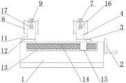
In the figure: 1. a base; 2. a hand-operated wheel; 3. a movable clamping block; 4. a first support plate; 5. a first knob; 6. a first rotating block; 7. a first latch; 8. a second turning block; 9. a second bolt; 10. a second knob; 11. a second branch block; 12. fixing the clamping block; 13. a chute; 14. a threaded rod; 15. a slider; 16. a first rotating lever; 17. a second rotating rod.
Detailed Description
The technical solutions in the embodiments of the present invention will be described clearly and completely with reference to the accompanying drawings in the embodiments of the present invention, and it is obvious that the described embodiments are only some embodiments of the present invention, not all embodiments. Based on the embodiments in the present invention, all other embodiments obtained by a person skilled in the art without creative work belong to the protection scope of the present invention.
Please refer to fig. 1-2, the utility model provides a technical solution of a clamp with good universality: comprises a base 1, one side of the top end of the base 1 is fixedly connected with a fixed clamping block 12, the other side of the top end of the base 1 is connected with a movable clamping block 3 in a sliding way, the top end of the movable clamping block 3 is fixedly connected with a first supporting plate 4, the inner side of the first supporting plate 4 is connected with a first rotating block 6 in a rotating way, the front side of the first supporting plate 4 is connected with a first knob 5 in a rotating way, the first knob 5 and the first rotating block 6 are connected through a first rotating rod 16 in a transmission way, the top end of the fixed clamping block 12 is fixedly connected with a second supporting block 11, the inner side of the second supporting block 11 is connected with a second rotating block 8 in a rotating way, the outer side of the second supporting block 11 is connected with a second knob 10 in a rotating way, the second knob 10 and the second rotating block 8 are connected through a second rotating rod 17 in a transmission way, the four surfaces of the second rotating block 8 and the four surfaces of the first rotating block 6 are respectively a transverse arc surface, a longitudinal arc surface, if the part is spherical, the two spherical concave surfaces of the first rotating block 6 and the second rotating block 8 correspond to each other, if the part is a pipe, the transverse arc surface or the longitudinal arc surface is selected to be used for clamping according to the machining type, and if the part is a regular part, the straight surface can be used for clamping.
Referring to fig. 2, a sliding groove 13 is formed in the top end of the base 1, a threaded rod 14 is connected to the sliding groove 13 in a rotating mode, a sliding block 15 is fixedly connected to the bottom end of the movable clamping block 3, the threaded rod 14 is in threaded connection with the sliding block 15, and a hand wheel 2 is fixedly connected to one end of the threaded rod 14 and used for driving the second rotating block 8 to move.
Referring to fig. 2, four grooves are formed in the outer surface of the first rotating rod 16 and the outer surface of the second rotating rod 17, a second bolt 9 is inserted into the top end of the second support block 11, a first bolt 7 is inserted into the top end of the first support plate 4, the bottom end of the first bolt 7 is matched with the groove in the surface of the first rotating rod 16, the bottom end of the second bolt 9 is matched with the groove in the surface of the second rotating rod 17, the four grooves in the surface of the first rotating rod 16 are corresponding to the four surfaces of the first rotating block 6, the grooves in the surface of the second rotating rod 17 are corresponding to the four surfaces of the second rotating block 8, and the top end of the second bolt 9 and the first bolt 7 are inserted into the grooves, so that the four surfaces of the second rotating block 8 and the four surfaces of the first rotating block 6 are positioned.
Referring to fig. 2, the top end of the second pin 9 and the top end of the first pin 7 are both fixedly connected with a cross rod, so that the top end of the second pin 9 and the first pin 7 can be conveniently plugged.
When the fixture is used in detail, the fixture with good universality can clamp parts with various shapes by pulling out the first bolt 7 and the second bolt 9, adjusting the first rotating block 6 and the second rotating block 8 according to the shapes of the parts, corresponding the two spherical concave surfaces of the first rotating block 6 and the second rotating block 8 if the parts are spherical, selecting a transverse arc surface or a longitudinal arc surface to clamp according to the processing type if the parts are tubes, clamping the parts by using a straight surface if the parts are regular parts, directly inserting the first bolt 7 and the second bolt 9 after the adjustment is finished, realizing the positioning of the first rotating block 6 and the second rotating block 8, then shaking the hand wheel 2, driving the sliding block 15 to move through the threaded rod 14 by the hand wheel 2, and comparing the existing fixture with the prior art by moving the first rotating block 6 to the second rotating block 8, the contact area is large, the clamping is more stable, and the precision is improved.
In the description of the present invention, it should be understood that the indicated orientation or positional relationship is based on the orientation or positional relationship shown in the drawings, and is only for convenience of description and simplification of description, and does not indicate or imply that the indicated device or element must have a particular orientation, be constructed and operated in a particular orientation, and thus should not be construed as limiting the present invention.
In the present invention, unless otherwise explicitly specified or limited, for example, it may be fixedly connected, detachably connected, or integrated; can be mechanically or electrically connected; they may be directly connected or indirectly connected through an intermediate medium, and may be connected through the inside of two elements or in an interaction relationship between two elements, unless otherwise specifically defined, and the specific meaning of the above terms in the present invention will be understood by those skilled in the art according to specific situations.
Although embodiments of the present invention have been shown and described, it will be appreciated by those skilled in the art that changes, modifications, substitutions and alterations can be made in these embodiments without departing from the principles and spirit of the invention, the scope of which is defined in the appended claims and their equivalents.
Claims (5)
1. Anchor clamps that commonality is good, including base (1), its characterized in that: the clamping device is characterized in that a fixed clamping block (12) is fixedly connected to one side of the top end of the base (1), a movable clamping block (3) is connected to the other side of the top end of the base (1) in a sliding manner, a first support plate (4) is fixedly connected to the top end of the movable clamping block (3), a first rotating block (6) is rotatably connected to the inner side of the first support plate (4), a first knob (5) is rotatably connected to the front side of the first support plate (4), the first knob (5) is rotatably connected with the first rotating block (6) through a first rotating rod (16), a second supporting block (11) is fixedly connected to the top end of the fixed clamping block (12), a second rotating block (8) is rotatably connected to the inner side of the second supporting block (11), a second knob (10) is rotatably connected to the outer side of the second supporting block (11), and the second knob (10) is rotatably connected with the second rotating block (8) through a second rotating rod (17), the four surfaces of the second rotating block (8) and the four surfaces of the first rotating block (6) are respectively a transverse arc surface, a longitudinal arc surface, a straight surface and a spherical concave surface.
2. The universal fixture of claim 1, wherein: spout (13) have been seted up on the top of base (1), the inside rotation of spout (13) is connected with threaded rod (14), move bottom fixedly connected with sliding block (15) of clamp splice (3), threaded rod (14) and sliding block (15) threaded connection, the hand wheel (2) of one end fixedly connected with of threaded rod (14).
3. The universal fixture of claim 1, wherein: four recesses have all been seted up to the surface of first dwang (16) and the surface of second dwang (17), the top of second piece (11) is pegged graft and is had second bolt (9), the top of first extension board (4) is pegged graft and is had first bolt (7), the bottom of first bolt (7) and the recess looks adaptation on first dwang (16) surface, the bottom of second bolt (9) and the recess looks adaptation on second dwang (17) surface.
4. The universal fixture of claim 3, wherein: four grooves on the surface of the first rotating rod (16) correspond to four surfaces of the first rotating block (6), and four grooves on the surface of the second rotating rod (17) correspond to four surfaces of the second rotating block (8).
5. The universal fixture of claim 3, wherein: the top of second bolt (9) and the top of first bolt (7) all fixedly connected with horizontal pole.
Priority Applications (1)
| Application Number | Priority Date | Filing Date | Title |
|---|---|---|---|
| CN202020927775.4U CN212553470U (en) | 2020-05-28 | 2020-05-28 | Clamp with good universality |
Applications Claiming Priority (1)
| Application Number | Priority Date | Filing Date | Title |
|---|---|---|---|
| CN202020927775.4U CN212553470U (en) | 2020-05-28 | 2020-05-28 | Clamp with good universality |
Publications (1)
| Publication Number | Publication Date |
|---|---|
| CN212553470U true CN212553470U (en) | 2021-02-19 |
Family
ID=74633050
Family Applications (1)
| Application Number | Title | Priority Date | Filing Date |
|---|---|---|---|
| CN202020927775.4U Active CN212553470U (en) | 2020-05-28 | 2020-05-28 | Clamp with good universality |
Country Status (1)
| Country | Link |
|---|---|
| CN (1) | CN212553470U (en) |
Cited By (1)
| Publication number | Priority date | Publication date | Assignee | Title |
|---|---|---|---|---|
| CN113664262A (en) * | 2021-09-23 | 2021-11-19 | 山东沂水机床厂有限公司 | Milling machine for clamping and processing special-shaped parts |
-
2020
- 2020-05-28 CN CN202020927775.4U patent/CN212553470U/en active Active
Cited By (1)
| Publication number | Priority date | Publication date | Assignee | Title |
|---|---|---|---|---|
| CN113664262A (en) * | 2021-09-23 | 2021-11-19 | 山东沂水机床厂有限公司 | Milling machine for clamping and processing special-shaped parts |
Similar Documents
| Publication | Publication Date | Title |
|---|---|---|
| CN212553470U (en) | Clamp with good universality | |
| CN214684978U (en) | Positioning device for welding titanium alloy tool pliers | |
| CN212265618U (en) | Connector housing clamping tool | |
| CN212653054U (en) | Clamping device for metal part machining | |
| CN213438348U (en) | Part fixing device for numerical control machine tool | |
| CN213318946U (en) | Key machining machine and jig for key machining machine | |
| CN211805620U (en) | Vice | |
| CN211661895U (en) | Electric automatization anchor clamps | |
| CN204053576U (en) | Keyseat clamp | |
| CN217224607U (en) | Tool support for milling machine dividing head | |
| CN111922938A (en) | Blade clamping device | |
| CN116765889B (en) | High-precision combined clamp capable of rapidly switching clamping diameter and direction | |
| CN215967563U (en) | Multi-angle clamp for deep hole drilling | |
| CN220144797U (en) | Tool for turning multi-angle elbow die forging joint | |
| CN212887206U (en) | Multifunctional clamp for machine manufacturing | |
| CN215280918U (en) | Clamping device for part machining | |
| CN218984497U (en) | Arc cylinder work piece centre gripping frock | |
| CN211249625U (en) | Positioning device for steel processing | |
| CN220922098U (en) | Locking structure for machining workpiece | |
| CN211680392U (en) | Tapping machine specialized tool | |
| CN209986592U (en) | Quick positioning tool for special-shaped shaft | |
| CN220463637U (en) | Clamp for manufacturing parts | |
| CN213004648U (en) | Fixture for grinding stepped shaft | |
| CN218874555U (en) | Bent pipe fixing mold | |
| CN211540327U (en) | Processing structure with high compatibility |
Legal Events
| Date | Code | Title | Description |
|---|---|---|---|
| GR01 | Patent grant | ||
| GR01 | Patent grant |