CN212521169U - Comprehensive equipment for vision prevention and control - Google Patents
Comprehensive equipment for vision prevention and control Download PDFInfo
- Publication number
- CN212521169U CN212521169U CN202020789600.1U CN202020789600U CN212521169U CN 212521169 U CN212521169 U CN 212521169U CN 202020789600 U CN202020789600 U CN 202020789600U CN 212521169 U CN212521169 U CN 212521169U
- Authority
- CN
- China
- Prior art keywords
- fixed
- fixedly connected
- people
- vision
- plate
- Prior art date
- Legal status (The legal status is an assumption and is not a legal conclusion. Google has not performed a legal analysis and makes no representation as to the accuracy of the status listed.)
- Expired - Fee Related
Links
Images

Landscapes
- Rehabilitation Tools (AREA)
Abstract
The utility model belongs to the technical field of vision prevention and control, in particular to comprehensive equipment for vision prevention and control, which comprises a seat plate, wherein the surface of the seat plate is fixedly connected with a connecting plate, a bearing is arranged on the surface of the connecting plate, a rotating shaft is arranged in the bearing, one end of the rotating shaft is fixedly connected with a threaded column, the surface of the threaded column is in threaded connection with a threaded pipe, and the other end of the rotating shaft is fixedly connected with a turntable; the utility model discloses, through setting up carousel and screw thread post, when people need highly adjust the back, people only need to rotate the carousel and drive the pivot and rotate, can drive the screw thread post simultaneously and rotate, under the interact of screw thread post and screwed pipe, thereby can drive the fixed plate and remove, and then can drive the back and remove, under the interact of carousel and screw thread post, thereby people are more swift when highly adjusting the back, and then can use the device to the people of co-altitude.
Description
Technical Field
The utility model belongs to the technical field of vision prevention and control, concretely relates to vision prevention and control's integrated equipment.
Background
The existing myopia prevention and control means mainly aims at relieving visual fatigue, and actually, especially for children, the vision is more caused by incorrect sitting posture, and the sitting posture of the children is difficult to ensure to be correct constantly under the conditions of writing, reading and the like, so that the vision is reduced quickly, a sitting posture maintaining device is lacked, the sitting posture of a user is easy to incline forwards, the cervical vertebra is not protected easily, meanwhile, the vision is difficult to be corrected and restored, and the existing device is inconvenient to adjust.
SUMMERY OF THE UTILITY MODEL
To solve the problems set forth in the background art described above. The utility model provides a comprehensive equipment of eyesight prevention and control has the characteristics of being convenient for adjust.
In order to achieve the above object, the utility model provides a following technical scheme: the utility model provides an equipment complex of vision prevention and control, includes the bedplate, bedplate fixed surface is connected with the connecting plate, wear to be equipped with the bearing on the connecting plate surface, wear to be equipped with the pivot in the bearing, pivot one end fixedly connected with screw thread post, screw thread post surface threaded connection has the screwed pipe, pivot other end fixedly connected with carousel, screwed pipe other end fixedly connected with fixed plate, fixed plate fixed surface fixedly connected with back, fixed plate fixed surface fixedly connected with slide bar, the sliding hole has been seted up on the connecting plate surface, slide bar and sliding hole phase-match, the back surface is provided with the constraint area.
Preferably, the fixed plate surface is fixedly connected with a supporting rod, the supporting rod surface is fixedly connected with a fixed pipe, a fixed rod is arranged in the fixed pipe, the fixed pipe surface is provided with a fixed box, a limiting rod penetrates through the fixed box surface, and a first spring is sleeved on the limiting rod surface.
Preferably, one end of the limiting rod is fixedly connected with a pull rod, a first clamping groove is formed in the surface of the fixing rod, the other end of the limiting rod is matched with the first clamping groove, a sliding groove is formed in the inner wall of the fixing pipe, a sliding block is connected in the sliding groove in a sliding mode, the other end of the sliding block is fixedly connected to the surface of the fixing rod, and a connecting rod is fixedly connected to the surface of the fixing rod.
Preferably, connecting rod other end fixedly connected with vision care appearance, connecting plate fixed surface is connected with the telescopic link, the second spring has been cup jointed on the telescopic link surface, telescopic link fixed surface is connected with the movable rod, the second draw-in groove has been seted up on the carousel surface, the telescopic link other end and second draw-in groove phase-match, the second draw-in groove is total a plurality ofly, and sets gradually on the carousel surface.
Preferably, the seat plate is fixedly connected with supporting legs, the supporting legs are fixedly connected with connecting legs, the connecting legs are fixedly connected with universal wheels, and the connecting legs are multiple in number and are sequentially connected to the surfaces of the supporting legs.
Compared with the prior art, the beneficial effects of the utility model are that:
the utility model, through the arrangement of the rotary disc and the threaded column, when people need to adjust the height of the backrest, people only need to rotate the rotary disc to drive the rotating shaft to rotate, and simultaneously can drive the threaded column to rotate, under the interaction of the threaded column and the threaded pipe, the fixed plate can be driven to move, and further the backrest can be driven to move, under the interaction of the rotary disc and the threaded column, people can adjust the height of the backrest more quickly, and further people with different heights can use the device, under the action of the constraint belt, the back of people can be limited, and further the sitting posture of people can be corrected, when people need to move the vision health care instrument, people only need to pull the pull rod to drive the limiting rod to move, so that the limiting rod can be separated from the first clamping groove, and people can move the fixed rod, and then can drive the connecting rod that carries the vision care appearance and remove, and then people can remove the vision care appearance, under the interact of gag lever post and dead lever to people are more swift when removing the vision care appearance, and then have improved people's work efficiency.
Drawings
The accompanying drawings are included to provide a further understanding of the invention, and are incorporated in and constitute a part of this specification, illustrate embodiments of the invention, and together with the description serve to explain the invention and not to limit the invention. In the drawings:
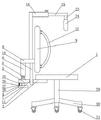
fig. 1 is a schematic structural view of a front view section of the present invention;
FIG. 2 is a front view of the present invention;
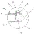
FIG. 3 is an enlarged schematic view of the structure at A in FIG. 1;
in the figure: 1. a seat plate; 2. a connecting plate; 3. a bearing; 4. a rotating shaft; 5. a threaded post; 6. a threaded pipe; 7. a turntable; 8. a fixing plate; 9. a backrest; 10. a slide bar; 11. a slide hole; 12. a binding belt; 13. a support bar; 14. a fixed tube; 15. fixing the rod; 16. a fixed box; 17. a limiting rod; 18. a first spring; 19. a pull rod; 20. a first card slot; 21. a chute; 22. a slider; 23. a connecting rod; 24. a vision health care instrument; 25. a telescopic rod; 26. a second spring; 27. a movable rod; 28. a second card slot; 29. supporting legs; 30. a connecting leg; 31. a universal wheel.
Detailed Description
The technical solutions in the embodiments of the present invention will be described clearly and completely with reference to the accompanying drawings in the embodiments of the present invention, and it is obvious that the described embodiments are only some embodiments of the present invention, not all embodiments. Based on the embodiments in the present invention, all other embodiments obtained by a person skilled in the art without creative work belong to the protection scope of the present invention.
Examples
Referring to fig. 1-3, the present invention provides the following technical solutions: the comprehensive equipment for vision prevention and control comprises a seat plate 1, wherein a connecting plate 2 is fixedly connected to the surface of the seat plate 1, a bearing 3 is arranged on the surface of the connecting plate 2 in a penetrating manner, a rotating shaft 4 is arranged in the bearing 3 in a penetrating manner, a threaded column 5 is fixedly connected to one end of the rotating shaft 4, a threaded pipe 6 is connected to the surface of the threaded column 5 in a threaded manner, a rotating disc 7 is fixedly connected to the other end of the rotating shaft 4, and by arranging the rotating disc 7 and the threaded column 5, when people need to adjust the height of a backrest 9, people only need to rotate the rotating disc 7 to drive the rotating shaft 4 to rotate and simultaneously drive the threaded column 5 to rotate, under the interaction of the threaded column 5 and the threaded pipe 6, a fixing plate 8 can be driven to move, and then the backrest 9 can be driven to move, under the interaction of the rotating disc 7 and the threaded column 5, so that people, the device can be further used for people with different heights, the other end of the threaded pipe 6 is fixedly connected with a fixing plate 8, the surface of the fixing plate 8 is fixedly connected with a backrest 9, the surface of the fixing plate 8 is fixedly connected with a sliding rod 10, the surface of the connecting plate 2 is provided with a sliding hole 11, the sliding rod 10 is matched with the sliding hole 11, the surface of the backrest 9 is provided with a constraint belt 12, and under the action of the constraint belt 12, the back of people can be limited, and the sitting posture of people can be further corrected.
Specifically, the fixed plate 8 fixed surface is connected with bracing piece 13, bracing piece 13 fixed surface is connected with fixed pipe 14, be provided with dead lever 15 in the fixed pipe 14, fixed pipe 14 surface is provided with fixed case 16, gag lever post 17 is worn to be equipped with on fixed case 16 surface, gag lever post 17 surface has cup jointed first spring 18.
Specifically, one end of the limiting rod 17 is fixedly connected with a pull rod 19, a first clamping groove 20 is formed in the surface of the fixing rod 15, the other end of the limiting rod 17 is matched with the first clamping groove 20, a sliding groove 21 is formed in the inner wall of the fixing pipe 14, a sliding block 22 is connected in the sliding groove 21 in a sliding mode, the other end of the sliding block 22 is fixedly connected to the surface of the fixing rod 15, and a connecting rod 23 is fixedly connected to the surface of the fixing rod 15.
Specifically, the other end of the connecting rod 23 is fixedly connected with the vision care instrument 24, when people need to move the vision care instrument 24, people only need to pull the pull rod 19 to drive the limiting rod 17 to move, so that the limiting rod 17 can be separated from the first clamping groove 20, people can move the fixed rod 15, and further can drive the connecting rod 23 carrying the vision care instrument 24 to move, and further people can move the vision care instrument 24, and under the interaction between the limiting rod 17 and the fixed rod 15, people can move the vision care instrument 24 more quickly, so that the working efficiency of people is improved, the surface of the connecting plate 2 is fixedly connected with a telescopic rod 25, the surface of the telescopic rod 25 is sleeved with a second spring 26, the surface of the telescopic rod 25 is fixedly connected with a movable rod 27, the surface of the turntable 7 is provided with a second clamping groove 28, and the other end of the telescopic rod 25 is matched with the second clamping groove 28, the second clamping grooves 28 are a plurality of and are sequentially formed in the surface of the rotary table 7.
Specifically, a supporting leg 29 is fixedly connected to the surface of the seat plate 1, a connecting leg 30 is fixedly connected to the surface of the supporting leg 29, a universal wheel 31 is fixedly connected to the surface of the connecting leg 30, and the connecting legs 30 are a plurality of in total and are sequentially connected to the surface of the supporting leg 29.
The utility model discloses a theory of operation and use flow: when the utility model is used, firstly, the device is placed at a proper position, when people need to adjust the height of the backrest 9, people firstly pull the movable rod 27 to move, so that the telescopic rod 25 can be separated from the second clamping groove 28, then people rotate the rotary disc 7, so that the rotary shaft 4 can be driven to rotate, and simultaneously the threaded column 5 can be driven to rotate, under the interaction of the threaded column 5 and the threaded pipe 6, the fixed plate 8 can be driven to move, so that the backrest 9 can be driven to move, then people fix people through the constraint belt 12, so that the sitting posture of people can be corrected, when people need to move the vision health care instrument 24, people only need to pull the pull rod 19 to drive the limiting rod 17 to move, so that the limiting rod 17 can be separated from the first clamping groove 20, so that people can move the fixed rod 15, and then the connecting rod 23 carrying the vision health care instrument 24 can be driven to move, and then people can move the vision health care instrument 24 to a proper position, so that people can use the vision health care instrument 24.
Finally, it should be noted that: although the present invention has been described in detail with reference to the foregoing embodiments, it will be apparent to those skilled in the art that modifications may be made to the embodiments described in the foregoing embodiments, or equivalents may be substituted for elements thereof. Any modification, equivalent replacement, or improvement made within the spirit and principle of the present invention should be included in the protection scope of the present invention.
Claims (5)
1. The utility model provides a comprehensive equipment of eyesight prevention and control, includes bedplate (1), its characterized in that: bedplate (1) fixed surface is connected with connecting plate (2), bearing (3) are worn to be equipped with on connecting plate (2) surface, wear to be equipped with pivot (4) in bearing (3), pivot (4) one end fixedly connected with screw thread post (5), screw thread post (5) surface threaded connection has screwed pipe (6), pivot (4) other end fixedly connected with carousel (7), screwed pipe (6) other end fixedly connected with fixed plate (8), fixed plate (8) fixed surface is connected with back (9), fixed plate (8) fixed surface is connected with slide bar (10), draw runner (11) have been seted up on connecting plate (2) surface, slide bar (10) and draw runner (11) phase-match, back (9) surface is provided with constraint area (12).
2. A vision prevention and control integrated device as recited in claim 1, further comprising: fixed plate (8) fixed surface is connected with bracing piece (13), bracing piece (13) fixed surface is connected with fixed pipe (14), be provided with dead lever (15) in fixed pipe (14), fixed pipe (14) surface is provided with fixed case (16), gag lever post (17) are worn to be equipped with on fixed case (16) surface, gag lever post (17) surface has cup jointed first spring (18).
3. A vision prevention and control integrated device as recited in claim 2, wherein: gag lever post (17) one end fixedly connected with pull rod (19), first draw-in groove (20) have been seted up on dead lever (15) surface, gag lever post (17) other end and first draw-in groove (20) phase-match, spout (21) have been seted up to fixed pipe (14) inner wall, sliding connection has slider (22) in spout (21), slider (22) other end fixed connection is on dead lever (15) surface, dead lever (15) fixed surface is connected with connecting rod (23).
4. A vision prevention and control integrated device as recited in claim 3, wherein: connecting rod (23) other end fixedly connected with vision care instrument (24), connecting plate (2) fixed surface is connected with telescopic link (25), second spring (26) have been cup jointed on telescopic link (25) surface, telescopic link (25) fixed surface is connected with movable rod (27), second draw-in groove (28) have been seted up on carousel (7) surface, telescopic link (25) other end and second draw-in groove (28) phase-match, second draw-in groove (28) are total a plurality ofly, and set gradually on carousel (7) surface.
5. A vision prevention and control integrated device according to claim 4, characterized in that: the seat plate (1) is fixedly connected with supporting legs (29) in the surface, the supporting legs (29) are fixedly connected with connecting legs (30) in the surface, the connecting legs (30) are fixedly connected with universal wheels (31) in the surface, the connecting legs (30) are multiple in total, and are sequentially connected to the surfaces of the supporting legs (29).
Priority Applications (1)
| Application Number | Priority Date | Filing Date | Title |
|---|---|---|---|
| CN202020789600.1U CN212521169U (en) | 2020-05-13 | 2020-05-13 | Comprehensive equipment for vision prevention and control |
Applications Claiming Priority (1)
| Application Number | Priority Date | Filing Date | Title |
|---|---|---|---|
| CN202020789600.1U CN212521169U (en) | 2020-05-13 | 2020-05-13 | Comprehensive equipment for vision prevention and control |
Publications (1)
| Publication Number | Publication Date |
|---|---|
| CN212521169U true CN212521169U (en) | 2021-02-12 |
Family
ID=74539830
Family Applications (1)
| Application Number | Title | Priority Date | Filing Date |
|---|---|---|---|
| CN202020789600.1U Expired - Fee Related CN212521169U (en) | 2020-05-13 | 2020-05-13 | Comprehensive equipment for vision prevention and control |
Country Status (1)
| Country | Link |
|---|---|
| CN (1) | CN212521169U (en) |
-
2020
- 2020-05-13 CN CN202020789600.1U patent/CN212521169U/en not_active Expired - Fee Related
Similar Documents
| Publication | Publication Date | Title |
|---|---|---|
| CN209090377U (en) | Integrated tables and chairs height and distance adjusting means | |
| CN206150821U (en) | Liftable computer desk | |
| CN212521169U (en) | Comprehensive equipment for vision prevention and control | |
| CN215029407U (en) | Traditional Chinese medicine grinding device | |
| CN108294923B (en) | Table-type visual function training device | |
| CN201480637U (en) | Multifunctional chair | |
| CN212465332U (en) | Special workstation of lifting support and animation design | |
| CN206261234U (en) | A kind of office chair | |
| CN209152729U (en) | A kind of leisure circle chair convenient for adjusting | |
| CN108523499A (en) | A kind of height-adjustable office seating | |
| CN214803631U (en) | Support and seat with regulatory function | |
| CN209421314U (en) | A kind of office desk | |
| CN210398273U (en) | Height adjusting device for computer display | |
| CN208550403U (en) | A kind of desktop placed type lifting computer desk | |
| CN209075236U (en) | A kind of quantum energy health care bed convenient for adjusting | |
| CN106108442A (en) | A kind of Multi-purpose chair | |
| CN208426368U (en) | A kind of Foldable massage chair | |
| CN208426365U (en) | A kind of novel folding massage armchair | |
| CN217695703U (en) | Practise calligraphy and use supplementary table chair with position of sitting correction function | |
| CN213820636U (en) | But rib angle regulation's office chair | |
| CN220800450U (en) | Limiting structure of sitting posture corrector | |
| CN213525083U (en) | Triple prism fixing frame for ophthalmic oblique amblyopia examination | |
| CN212972327U (en) | Novel ergonomic office chair | |
| CN217565268U (en) | Multifunctional lifting type office table | |
| CN211705098U (en) | Head and neck surgery fixing frame convenient to adjust |
Legal Events
| Date | Code | Title | Description |
|---|---|---|---|
| GR01 | Patent grant | ||
| GR01 | Patent grant | ||
| CF01 | Termination of patent right due to non-payment of annual fee |
Granted publication date: 20210212 |
|
| CF01 | Termination of patent right due to non-payment of annual fee |