CN212518022U - Power distribution cabinet convenient to assemble - Google Patents
Power distribution cabinet convenient to assemble Download PDFInfo
- Publication number
- CN212518022U CN212518022U CN202020603142.8U CN202020603142U CN212518022U CN 212518022 U CN212518022 U CN 212518022U CN 202020603142 U CN202020603142 U CN 202020603142U CN 212518022 U CN212518022 U CN 212518022U
- Authority
- CN
- China
- Prior art keywords
- movable rod
- cabinet door
- bolt
- curb plate
- main frame
- Prior art date
- Legal status (The legal status is an assumption and is not a legal conclusion. Google has not performed a legal analysis and makes no representation as to the accuracy of the status listed.)
- Expired - Fee Related
Links
Images


Abstract
The utility model discloses a switch board convenient to assembly, including main frame, curb plate, cabinet door, the main frame is C shape, the curb plate is connected through the pivot with the main frame, the curb plate passes through hinged joint with the cabinet door, the curb plate inboard is equipped with the curb plate bolt, cabinet door inboard is equipped with the cabinet door bolt, the curb plate bolt comprises last movable rod, lower movable rod, connecting rod, fixing base, pivot, knob, it all is equipped with solid fixed ring to go up movable rod and lower movable rod end, main frame edge inboard is equipped with a plurality of apertures, curb plate bolt and cabinet door bolt can insert in the aperture. The utility model discloses a bolt is fixed switch board curb plate and cabinet door plant, and accessible shrink bolt expandes cabinet door and curb plate completely when assembling components and parts in to the switch board, and the many people of being convenient for are under construction, improve the installation effectiveness.
Description
Technical Field
The utility model belongs to the technical field of switch board equipment, specifically be a switch board convenient to assembly.
Background
The power distribution cabinet is a control center for distributing power to various components in a power supply line, is usually made of steel plates, has the characteristics of small volume, convenience in installation, high space utilization rate and the like, is mainly used for distributing power, is convenient for opening and closing the circuit, can visually display the conduction state of the circuit, and is a final-stage device of a circuit system.
Switch board internally mounted has a large amount of components and parts, and present switch board cabinet door is less, and it is narrow to open the back space, only is fit for an installer and installs the operation, leads to assembly efficiency low.
SUMMERY OF THE UTILITY MODEL
The utility model aims at providing a switch board convenient to assembly to the switch board cabinet door that proposes in the solution background art is little, opens the back space narrow, problem that assembly efficiency is low.
In order to achieve the above object, the present invention provides the following solutions: the utility model provides a switch board convenient to assembly, includes main frame, curb plate, cabinet door, its characterized in that: the cabinet door is characterized in that the main frame is C-shaped, a first rotating shaft is arranged at the joint of the side plate and the main frame, the side plate can be opened outwards along the first rotating shaft, a hinge is arranged at the joint of the side plate and the cabinet door and used for opening and closing the cabinet door, a side plate bolt is arranged on the inner side of the side plate and used for fixing the side plate on the main frame, a cabinet door bolt is arranged on the inner side of the cabinet door and used for fixing the cabinet door on the main frame, a handle is arranged on the outer side of the cabinet door and provided with a door lock, and a plurality of small holes.
Further, the side plate bolt and the cabinet door bolt have the same structure as follows: go up movable rod, lower movable rod, connecting rod, fixing base, second pivot, movable rod retainer plate, the curb plate bolt still is equipped with the knob.
Further, the pivot is installed perpendicularly on the fixing base, the connecting rod is installed perpendicularly in the second pivot, the connecting rod both ends respectively with go up the movable rod and the movable rod is connected down, makes the connecting rod can drive go up the movable rod and the movable rod removes down.
Further, the tail ends of the upper movable rod and the lower movable rod are provided with the movable rod fixing ring, the tail ends of the upper movable rod and the lower movable rod penetrate through the movable rod fixing ring, and the movable rod fixing ring is fixedly installed on the side plate and the cabinet door.
Further, the upper movable rod and the lower movable rod can be inserted into the small hole.
Further, the knob can drive the connecting rod to rotate, and the door lock can drive the connecting rod to rotate.
Through the arrangement, the door lock is opened and rotated to enable the cabinet door bolt to be retracted from the small hole so as to open the cabinet door, and then the knob is rotated to enable the side plate bolt to be retracted from the small hole so as to enable the side plate to rotate to the outer side of the main frame along the first rotating shaft, so that the side plate and the cabinet door are completely unfolded.
Compared with the prior art, the utility model has the advantages that:
1. the utility model discloses a curb plate and cabinet door are fixed through the bolt, and the curb plate all is connected through the rotation mode with main frame and cabinet door, can make the bolt withdraw when installing components and parts in to the switch board, and the duplex winding hinge or first pivot rotate, expand to the main frame outside, and each accessory of switch board inside easy to assemble rotates curb plate and cabinet door after the installation is accomplished, inserts the aperture with curb plate bolt and cabinet door bolt and can close the switch board completely.
2. The utility model discloses a curb plate and cabinet door can be opened to the main frame outside completely, when needs overhaul the maintenance to the equipment in the switch board, can overhaul the operation again after opening cabinet door and curb plate, provide bigger operation space, convenient the maintenance.
Drawings
Fig. 1 is a perspective view of the closed state of the cabinet door of the utility model.
Fig. 2 is a perspective view of the cabinet door and the side plate in an unfolded state.
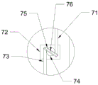
Fig. 3 is an enlarged view of a portion a in fig. 2.
Fig. 4 is an enlarged view of fig. 2 at B.
In the figure: 1. a main frame; 2. a side plate; 3. a cabinet door; 4. a first rotating shaft; 5. a hinge; 6. a handle; 7. a side plate bolt; 8. a cabinet door bolt; 9. a small hole; 10. a door lock is provided.
Detailed Description
The technical solution in the embodiments of the present invention will be clearly and completely described below with reference to the accompanying drawings in the embodiments of the present invention. It is to be understood that the embodiments described are only some embodiments of the invention, and not all embodiments. Based on the embodiments of the present invention, all other embodiments obtained by a person of ordinary skill in the art without creative efforts belong to the protection scope of the present invention.
Referring to fig. 1-4, the utility model provides a technical scheme: the utility model provides a switch board convenient to assembly, includes main frame 1, curb plate 2, cabinet door 3, its characterized in that: main frame 1 is the C shape, curb plate 2 is equipped with first pivot 4 with 1 junction of main frame, it is rotatory to make curb plate 2 can wind first pivot 4, increase curb plate 2 and main frame 1's contained angle simultaneously, curb plate 2 is equipped with hinge 5 with cabinet door 3 junction, be used for opening cabinet door 3, 2 inboards of curb plate are equipped with curb plate bolt 7, be used for fixed curb plate 7, 3 inboards of cabinet door are equipped with cabinet door bolt 8, be used for fixed cabinet door 3, the cabinet door 3 outside is equipped with handle 6, handle 6 is equipped with lock 10, 1 top surface of main frame and bottom surface edge inboard are equipped with a plurality of apertures 9.
Preferably, the side plate bolt 7 and the cabinet door bolt 8 have the same structure as follows: the upper movable rod 71, the lower movable rod 73, the connecting rod 75, the fixed seat 72, the second rotating shaft 74, the movable rod fixing ring 77 and the side plate bolt 7 are further provided with a knob 76.
Preferably, the second rotating shaft 74 is vertically installed on the fixing base 72, the connecting rod 75 is vertically installed on the second rotating shaft 74, so that the connecting rod 75 can rotate around the second rotating shaft 74, two ends of the connecting rod 75 are respectively connected with the upper movable rod 71 and the lower movable rod 73, and when the second rotating shaft 74 is rotated, the upper movable rod 71 and the lower movable rod 73 can move up and down.
Preferably, the ends of the upper movable rod 71 and the lower movable rod 73 are both provided with a movable rod fixing ring 77, the ends of the upper movable rod 71 and the lower movable rod 73 both penetrate through the movable rod fixing ring 77, and the movable rod fixing ring 77 is fixedly mounted on the side plate 2 and the cabinet door 3 and used for limiting the positions of the upper movable rod 71 and the lower movable rod 73.
Preferably, the upper movable rod 71 and the lower movable rod 73 are inserted into the small hole 9, thereby fixing the cabinet door 3 and the side plate 7.
Preferably, the knob 76 rotates the link 75 and the door lock 10 rotates the link 75.
During the assembly switch board, open lock 10 and rotation, make cabinet door bolt 8 take out from aperture 9, pulling handle 6 makes cabinet door 3 open to the 1 outside of main frame, then rotates knob 76, makes curb plate bolt 7 take out from aperture 9, can promote curb plate 2 and open to the 1 outside of main frame, finally makes curb plate 2 and cabinet door 3 extend completely, thereby be convenient for a plurality of installer to main frame 1, 2 inboard various components and parts of installation of curb plate, realize improving assembly efficiency's effect. After the components and parts are installed, the side plates 2 and the cabinet door 3 are restored to the original positions, and the side plate bolts 7 and the cabinet door bolts 8 are used for fixing, so that the cabinet can be normally used.
The above description is only the specific embodiment of the preferred embodiment of the present invention, but the protection scope of the present invention is not limited thereto, and any person skilled in the art can substitute or change the technical solution of the present invention and the inventive concept based on the technical solution of the present invention within the technical scope disclosed in the present invention, and all the modifications should be covered within the protection scope of the present invention.
Claims (6)
1. The utility model provides a switch board convenient to assembly, includes main frame (1), curb plate (2), cabinet door (3), its characterized in that: the improved cabinet door is characterized in that the main frame (1) is C-shaped, the side plate (2) is provided with a first rotating shaft (4) at the joint of the main frame (1), the side plate (2) is provided with a hinge (5) at the joint of the cabinet door (3), a side plate bolt (7) is arranged on the inner side of the side plate (2), a cabinet door bolt (8) is arranged on the inner side of the cabinet door (3), a handle (6) is arranged on the outer side of the cabinet door (3), a door lock (10) is arranged on the handle (6), and a plurality of small holes (9) are formed in the inner sides of the top surface and.
2. The power distribution cabinet convenient to assemble according to claim 1, wherein: the side plate bolt (7) and the cabinet door bolt (8) have the same structure as follows: the side plate bolt (7) is also provided with a knob (76), wherein the upper movable rod (71), the lower movable rod (73), a connecting rod (75), a fixed seat (72), a second rotating shaft (74) and a movable rod fixing ring (77).
3. The power distribution cabinet convenient to assemble according to claim 2, wherein: second pivot (74) is installed perpendicularly on fixing base (72), connecting rod (75) are installed perpendicularly on second pivot (74), connecting rod (75) both ends respectively with go up movable rod (71) and lower movable rod (73) are connected.
4. The power distribution cabinet convenient to assemble according to claim 2, wherein: go up movable rod (71) and the end of activity pole (73) all is equipped with down movable rod retainer plate (77), go up movable rod (71) and the end of activity pole (73) is all followed down pass in movable rod retainer plate (77), movable rod retainer plate (77) fixed mounting be in curb plate (2) and on cabinet door (3).
5. The power distribution cabinet convenient to assemble according to claim 2, wherein: the upper movable rod (71) and the lower movable rod (73) can be inserted into the small hole (9).
6. The power distribution cabinet convenient to assemble according to claim 2, wherein: the knob (76) can drive the connecting rod (75) to rotate, and the door lock (10) can drive the connecting rod (75) to rotate.
Priority Applications (1)
| Application Number | Priority Date | Filing Date | Title |
|---|---|---|---|
| CN202020603142.8U CN212518022U (en) | 2020-04-21 | 2020-04-21 | Power distribution cabinet convenient to assemble |
Applications Claiming Priority (1)
| Application Number | Priority Date | Filing Date | Title |
|---|---|---|---|
| CN202020603142.8U CN212518022U (en) | 2020-04-21 | 2020-04-21 | Power distribution cabinet convenient to assemble |
Publications (1)
| Publication Number | Publication Date |
|---|---|
| CN212518022U true CN212518022U (en) | 2021-02-09 |
Family
ID=74434247
Family Applications (1)
| Application Number | Title | Priority Date | Filing Date |
|---|---|---|---|
| CN202020603142.8U Expired - Fee Related CN212518022U (en) | 2020-04-21 | 2020-04-21 | Power distribution cabinet convenient to assemble |
Country Status (1)
| Country | Link |
|---|---|
| CN (1) | CN212518022U (en) |
-
2020
- 2020-04-21 CN CN202020603142.8U patent/CN212518022U/en not_active Expired - Fee Related
Similar Documents
| Publication | Publication Date | Title |
|---|---|---|
| CN212518022U (en) | Power distribution cabinet convenient to assemble | |
| JPH02144673U (en) | ||
| CN214625883U (en) | Electrical cabinet for electrical engineering | |
| CN210247252U (en) | Multifunctional communication device cabinet convenient to open and close | |
| CN211422214U (en) | Comprehensive power distribution cabinet device convenient to overhaul | |
| CN219576249U (en) | Outdoor distribution box | |
| CN217681218U (en) | Intelligent window opener | |
| CN214379502U (en) | Block terminal convenient to firm installation | |
| CN216416518U (en) | Operation management device for offshore wind power equipment | |
| CN210725598U (en) | Outdoor communication cabinet with cabinet door limiter | |
| CN205297830U (en) | Pylon platform cover turning device and wind generating set pylon | |
| CN217934779U (en) | Protection switch board of built-in isolated wheelbarrow | |
| CN217217114U (en) | Maintain convenient front maintenance formula IBP dish | |
| CN210779542U (en) | Natural ventilation heat dissipation type outdoor electric power cabinet | |
| CN211656669U (en) | Outdoor suspension type electric cabinet | |
| CN217036329U (en) | Vertical multifunctional distribution box | |
| CN220797528U (en) | Indoor closed power distribution cabinet | |
| CN218840301U (en) | Magnesium alloy die-casting box | |
| CN217766570U (en) | Waterproof ammeter box | |
| CN215989862U (en) | Block terminal easy to assemble | |
| CN219643376U (en) | Novel distribution box | |
| CN211743794U (en) | Variable peel formula switching station casing | |
| CN209930653U (en) | Electromechanical automation switch board that can assemble | |
| CN212517925U (en) | Protection against electric shock type distribution control cabinet | |
| CN210955869U (en) | Electric power iron tower signboard fixed bolster |
Legal Events
| Date | Code | Title | Description |
|---|---|---|---|
| GR01 | Patent grant | ||
| GR01 | Patent grant | ||
| CF01 | Termination of patent right due to non-payment of annual fee | ||
| CF01 | Termination of patent right due to non-payment of annual fee |
Granted publication date: 20210209 |