CN212513029U - Pendulum body core device of laser demarcation device - Google Patents
Pendulum body core device of laser demarcation device Download PDFInfo
- Publication number
- CN212513029U CN212513029U CN202021277153.8U CN202021277153U CN212513029U CN 212513029 U CN212513029 U CN 212513029U CN 202021277153 U CN202021277153 U CN 202021277153U CN 212513029 U CN212513029 U CN 212513029U
- Authority
- CN
- China
- Prior art keywords
- frame
- pendulum
- laser module
- swing
- pendulum body
- Prior art date
- Legal status (The legal status is an assumption and is not a legal conclusion. Google has not performed a legal analysis and makes no representation as to the accuracy of the status listed.)
- Active
Links
Images


Abstract
The utility model discloses a pendulum body core device of a laser demarcation device, which comprises a laser module, a pendulum body frame and a base, wherein the pendulum body frame comprises a hollow pendulum frame outer frame and a hollow pendulum frame inner frame, and the pendulum frame inner frame is fixedly connected with the pendulum body frame; the laser module comprises a horizontal laser module and a vertical laser module, the horizontal laser module is arranged in the swing frame through a swing frame inner frame, and the swing frame inner frame is fixedly connected with the horizontal laser module; the vertical laser module is fixedly connected with the pendulum body frame, a wire guide plate is arranged in the pendulum body frame, and the wire guide plate is electrically connected with the horizontal laser module and the vertical laser module respectively; the swing frame outer frame is connected with the swing body frame through a horizontal laser module, and the swing frame outer frame is connected with the swing frame inner frame through a bearing; and a stopping device for controlling the swinging body to swing is arranged at the bottom of the swinging body frame. The utility model discloses multiple functional, rational in infrastructure, solved and projected the laser line and bright inhomogeneous pendulum body core device of laser demarcation appearance.
Description
Technical Field
The utility model relates to a laser range finder technical field, in particular to pendulum body core device of laser demarcation appearance.
Background
In the field of laser demarcation devices, the laser demarcation device is complex in design and manufacturing process, and in order to obtain better precision, a bearing assembly mode for enabling a pendulum body to move is designed to be screw fastening, so that the precision is convenient to debug. In addition, for the convenience of counterweight and manufacturing, most of the laser modules are designed to be eccentric, i.e. the vertical laser module and the horizontal laser module are not on the same axis and usually deviate from 5-10mm, so as to reduce counterweight. However, after the laser is projected, the light intensity is inconsistent due to the inconsistent center, and the problem is obvious when the working radius exceeds 20 meters.
The Chinese patent application numbers are: 201910182955.6, application date is 03 and 12 in 2019, and publication date is: year 2019, month 05, day 10, with patent names: the invention discloses a portable pendulum type automatic leveling laser plumbing point instrument, which comprises a shell, wherein an outer ring is arranged in the shell, an inner ring which can swing left and right and is provided with a light through hole is rotatably arranged in the middle of the outer ring, a pendulum body is arranged below the inner ring, a copper block is arranged at the bottom of the pendulum body, two sides of the top of the pendulum body are respectively provided with an integrated mounting seat, and the mounting seats are respectively rotatably arranged on the left side and the right side of the inner ring so that the pendulum body can swing back and forth relative to the inner ring; the pendulum is internally provided with a laser module mounting hole, a laser module is mounted in the laser module mounting hole, and laser emitted by the laser module upwards passes through the light through hole of the inner ring. The invention has simple structure, small volume and convenient carrying, and can replace a line pendant.
The patent literature discloses a portable pendulum type automatic leveling laser plumbing and pointing instrument, but the laser plumbing and pointing instrument can only plumb and point for distance measurement, cannot measure the distance horizontally, is single in function, is not accurate enough in distance measurement, and cannot meet the requirements of consumers.
SUMMERY OF THE UTILITY MODEL
The utility model aims at providing a multiple functional, rational in infrastructure, solved and projected the laser line and bright inhomogeneous pendulum body core device of laser demarcation appearance.
In order to achieve the purpose of the utility model, the utility model provides a pendulum body core device of a laser demarcation device, which comprises a laser module, a pendulum body frame and a base, wherein the pendulum body frame is arranged in the base and comprises a hollow pendulum body outer frame and a hollow pendulum body inner frame, and the pendulum body inner frame is fixedly connected with the pendulum body frame; the laser module comprises a horizontal laser module and at least one vertical laser module, the horizontal laser module is arranged in the swing frame through the swing frame inner frame, and the swing frame inner frame is fixedly connected with the horizontal laser module; the vertical laser module is fixedly connected with the pendulum body frame, and a wire guide plate is also arranged in the pendulum body frame and is respectively and electrically connected with the horizontal laser module and the vertical laser module;
the base is provided with a stand column, the stand column is connected with the outer frame of the swing frame, the outer frame of the swing frame is connected with the swing body frame through a horizontal laser module, and the outer frame of the swing frame is connected with the inner frame of the swing frame through a bearing; the bottom of the pendulum body frame is provided with a stopping device for controlling the pendulum body to swing; the pendulum body frame is fixedly connected with the base through the stopping device.
The vertical laser module comprises two vertical laser modules.
The pendulum body frame also comprises at least one balancing weight for adjusting the balance of the pendulum body.
Preferably, the weight comprises two weights.
The horizontal laser module comprises a base, and the inner frame of the swing frame is connected with the horizontal laser module through the base.
The two sides of the pendulum frame are provided with lifting lugs, and the inner frame of the pendulum frame is fixedly connected with the pendulum frame through the lifting lugs.
The stopping device comprises a hollow copper moving block, a convex block is arranged at the lower part of the pendulum body frame, and the copper moving block is fixedly connected with the pendulum body frame through the convex block.
The stopping device also comprises a hollow strong magnetic steel, and the copper moving block is arranged in the strong magnetic steel.
The base is provided with a groove, the size of the groove corresponds to that of the strong magnetic steel, and the strong magnetic steel is arranged in the groove
The utility model has the advantages that 1) the utility model directly uses two sides of the shaft lever to connect the bearing and the pendulum body frame, and the precision is controlled by the automatic equipment in the assembling process, so as to keep the stability and consistency of the product quality; 2) the utility model can simultaneously carry out horizontal and vertical accurate throw point tests, has complete functions and accurate distance measurement, and improves the production efficiency; 3) the utility model discloses the even horizontal module X, Y axle of arranging of pendulum body laser module coincide simultaneously, has solved the bright dark inhomogeneous condition of projection laser line.
Drawings
In order to more clearly illustrate the embodiments of the present invention or the technical solutions in the prior art, the drawings needed to be used in the description of the embodiments or the prior art will be briefly described below, it is obvious that the drawings in the following description are only some embodiments of the present invention, and for those skilled in the art, other drawings can be obtained according to the structures shown in the drawings without creative efforts.
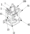
Fig. 1 is a schematic perspective view of a pendulum movement device of a laser demarcation device according to an embodiment of the present invention;
fig. 2 is a disassembly schematic view of a pendulum movement device of the laser demarcation device of the present invention;
fig. 3 is a front view of the pendulum movement device of the laser demarcation device of the present invention.
The reference numbers illustrate:


the objects, features and advantages of the present invention will be further described with reference to the accompanying drawings.
Detailed Description
The technical solutions in the embodiments of the present invention will be described clearly and completely with reference to the accompanying drawings in the embodiments of the present invention, and it is obvious that the described embodiments are only some embodiments of the present invention, not all embodiments. Based on the embodiments in the present invention, all other embodiments obtained by a person skilled in the art without creative efforts belong to the protection scope of the present invention.
It should be noted that all the directional indicators (such as upper, lower, left, right, front and rear … …) in the embodiment of the present invention are only used to explain the relative position relationship between the components, the motion situation, etc. in a specific posture (as shown in the drawings), and if the specific posture is changed, the directional indicator is changed accordingly.
In the present application, unless expressly stated or limited otherwise, the terms "connected" and "fixed" are to be construed broadly, e.g., "fixed" may be fixedly connected or detachably connected, or integrally formed; can be mechanically or electrically connected; they may be directly connected or indirectly connected through intervening media, or they may be connected internally or in any other suitable relationship, unless expressly stated otherwise. The specific meaning of the above terms in the present invention can be understood according to specific situations by those skilled in the art.
In addition, descriptions in the present application as to "first", "second", and the like are for descriptive purposes only and are not to be construed as indicating or implying relative importance or implicit to the number of technical features indicated. Thus, a feature defined as "first" or "second" may explicitly or implicitly include at least one such feature. In addition, the technical solutions in the embodiments may be combined with each other, but it must be based on the realization of those skilled in the art, and when the technical solutions are contradictory or cannot be realized, the combination of the technical solutions should not be considered to exist, and is not within the protection scope of the present invention.
The utility model provides a pendulum body core device of laser demarcation appearance.
Referring to fig. 1 to 3, in an embodiment of the present invention, the pendulum movement device of the laser demarcation device includes a laser module, a pendulum frame 7 and a base 12, wherein the pendulum frame 7 is disposed in the base 12, the pendulum frame 7 includes a hollow pendulum frame outer frame 2 and a hollow pendulum frame inner frame 5, and the pendulum frame inner frame 5 is fixedly connected to the pendulum frame 7; the laser module comprises a horizontal laser module 1 and at least one vertical laser module; preferably, the vertical laser module includes two vertical laser modules 91 and 92.
The horizontal laser module 1 is arranged in the swing frame 7 through the swing frame inner frame 5, and the swing frame inner frame 5 is fixedly connected with the horizontal laser module 1; the vertical laser module 91 and the vertical laser module 92 are respectively fixedly connected with the pendulum body frame 7, a wire guide plate 8 is further arranged in the pendulum body frame 7, and the wire guide plate 8 is respectively and electrically connected with the horizontal laser module 1, the vertical laser module 91 and the vertical laser module 92;
the base 12 is provided with a vertical column 13, a vertical column 131 and a vertical column 132, and the vertical column 13, the vertical column 131 and the vertical column 132 are respectively connected with the swing frame outer frame 2 through an edge hole 212, an edge hole 214 and an edge hole 213 on the swing frame outer frame 2; preferably, a fourth upright post (not shown) may be disposed on the base and connected to the swing frame outer frame 2 through a rim hole 211 on the swing frame outer frame 2. The base 12 is connected with the swing frame outer frame 2 through the upright post 13, the upright post 131 and the upright post 132, so that the swing frame outer frame 2 is more stable.
The swing frame outer frame 2 is connected with the swing body frame 7 through the horizontal laser module 1, and one side of the swing frame outer frame 2 is connected with one side of the inner frame 5 through a bearing 3 and a shaft lever 31 which penetrate through a hole 221 of the swing frame outer frame 2; the other side of the swing frame outer frame 2 passes through a hole 212 of the swing frame outer frame 2 through a bearing 4 and a shaft lever 41 and is connected with the other side of the swing frame inner frame 5;
the bottom of the pendulum body frame 7 is provided with a stopping device for controlling the pendulum body to swing; the pendulum support 7 is fixedly connected to the base 12 via the blocking device.
In this embodiment, the two sides of the swing frame 7 are provided with a lifting lug 71 and a lifting lug 72, the lifting lug 71 is provided with a hole 711, the lifting lug 72 is also provided with a hole 721, and one side of the inner frame 2 of the swing frame is connected with the lifting lug 72 through a bearing 51 and a shaft lever 511 and then through the lifting lug hole 721; the other side of the inner swing frame 2 is connected with the lifting lug 71 through the bearing 52 and the shaft rod 512 and the lifting lug hole 711, so that the inner swing frame 2 is fixedly connected with the swing frame 7.
In this embodiment, the horizontal laser module 1, the vertical laser module 91, and the vertical laser module 92 are fixed on the pendulum frame 7 by screws. The shaft rod 41 is arranged on the 4 bearings, fixed through glue, the fixed bearing shaft rod is assembled on the inner frame 5 of the swing frame and connected to the swing body frame 7, fixed through the glue, and symmetrical in two sides; thus, the swing frame 7 can freely move in the X-axis direction; then, the fixed bearing shaft rod is assembled on the pendulum body outer frame 2, and meanwhile, the bearing shaft rod is assembled and inserted into the pendulum body inner frame 5 which is assembled with the pendulum body frame 7, and the bearing shaft rod is fixed by glue, so that the pendulum body 100 can freely move along the Y-axis direction, and the pendulum body 100 can freely move along the X-Y axis direction.
In this embodiment, the wire guide plate 8 is mounted in the pendulum frame 7 by using screws, and is welded and conducted with the horizontal laser module 1, the vertical laser module 91, and the vertical laser module 92; when the power supply is connected, all the lasers work to meet the design requirement of projecting laser lines. All laser lines are kept straight through screw adjustment, and X, Y, Z included angles in three axial directions form right angles of 90 degrees.
Referring to fig. 1, 2, and 3, in this embodiment, the pendulum frame 7 further includes at least one weight 6 for adjusting the balance of the pendulum. Preferably, the weight comprises two weights 6 and 61. The weight block 6 and the weight block 61 are mainly used for adjusting the balance of the pendulum body 100.
In this embodiment, the stopping device includes a hollow copper moving block 10, a protrusion 75 is disposed at a lower portion of the pendulum frame 7, and the copper moving block 10 is fixedly connected to the pendulum frame 7 through the protrusion 75.
The preventing device further comprises a hollow strong magnetic steel 11, and the copper moving block 10 is arranged in the strong magnetic steel 11.
The base 12 is provided with a groove 121, the size of the groove 121 corresponds to that of the strong magnetic steel 11, and the strong magnetic steel 11 is arranged in the groove 121
In this embodiment, the assembled pendulum body 100 is installed in the upright post 13, the upright post 131 and the upright post 132, and then the copper moving block 10 is installed at the bottom of the pendulum body 100; and the strong magnetic steel 11 is arranged in the base 12 and fixed. Then, the pendulum 100 with the locked upright post is installed in the base 12 to which the ferromagnetic magnetic steel 11 is fixed, so that the pendulum 100 can be suspended, and the X, Y shaft can freely move in two directions.
At this time, when the copper moving block 10 receives the magnetic force lines of the strong magnetic steel, the movement is disturbed, so that the pendulum body is forced to stop moving quickly, and the magnetic damping effect is achieved; by installing the counterweight block 6 and the counterweight block 61, the projected laser lines are kept horizontally parallel, so that the pendulum body 100 can obtain the horizontal laser lines, the horizontal function is realized, and meanwhile, the magnetic damping mechanism works, so that the obtained horizontal lines can be quickly forbidden to be used as construction standard horizontal lines.
The above only is the preferred embodiment of the present invention, not so limiting the patent scope of the present invention, without departing from the spirit and scope of the present invention, the present invention can also have various changes and improvements, all under the inventive concept, utilize the equivalent structure transformation made by the contents of the specification and the drawings, or directly/indirectly use in other related technical fields all included in the patent protection scope of the present invention.
Claims (9)
1. The utility model provides a pendulum body core device of laser demarcation appearance, includes laser module, pendulum body frame, base, pendulum body frame sets up in the base, its characterized in that: the pendulum frame comprises a hollow pendulum frame outer frame and a hollow pendulum frame inner frame, and the pendulum frame inner frame is fixedly connected with the pendulum frame; the laser module comprises a horizontal laser module and at least one vertical laser module, the horizontal laser module is arranged in the swing frame through the swing frame inner frame, and the swing frame inner frame is fixedly connected with the horizontal laser module; the vertical laser module is fixedly connected with the pendulum body frame, and a wire guide plate is also arranged in the pendulum body frame and is respectively and electrically connected with the horizontal laser module and the vertical laser module;
the base is provided with a stand column, the stand column is connected with the outer frame of the swing frame, the outer frame of the swing frame is connected with the swing body frame through a horizontal laser module, and the outer frame of the swing frame is connected with the inner frame of the swing frame through a bearing; the bottom of the pendulum body frame is provided with a stopping device for controlling the pendulum body to swing; the pendulum body frame is fixedly connected with the base through the stopping device.
2. The pendulum movement device of a laser demarcation device according to claim 1, wherein: the vertical laser module comprises two vertical laser modules.
3. The pendulum movement device of a laser demarcation device according to claim 1, wherein: the pendulum body frame also comprises at least one balancing weight for adjusting the balance of the pendulum body.
4. The pendulum movement device of a laser demarcation device according to claim 3, wherein: the balancing weight comprises two balancing weights.
5. The pendulum movement device of a laser demarcation device according to claim 1, wherein: the horizontal laser module comprises a base, and the inner frame of the swing frame is connected with the horizontal laser module through the base.
6. The pendulum movement device of a laser demarcation device according to claim 1, wherein: the two sides of the pendulum frame are provided with lifting lugs, and the inner frame of the pendulum frame is fixedly connected with the pendulum frame through the lifting lugs.
7. A pendulum movement apparatus of a laser demarcation device according to any one of claims 1 to 6, wherein: the stopping device comprises a hollow copper moving block, a convex block is arranged at the lower part of the pendulum body frame, and the copper moving block is fixedly connected with the pendulum body frame through the convex block.
8. The pendulum movement device of a laser demarcation device according to claim 7, wherein: the stopping device also comprises a hollow strong magnetic steel, and the copper moving block is arranged in the strong magnetic steel.
9. The pendulum movement device of a laser demarcation device according to claim 8, wherein: the base is provided with a groove, the size of the groove corresponds to that of the strong magnetic steel, and the strong magnetic steel is arranged in the groove.
Priority Applications (1)
| Application Number | Priority Date | Filing Date | Title |
|---|---|---|---|
| CN202021277153.8U CN212513029U (en) | 2020-07-03 | 2020-07-03 | Pendulum body core device of laser demarcation device |
Applications Claiming Priority (1)
| Application Number | Priority Date | Filing Date | Title |
|---|---|---|---|
| CN202021277153.8U CN212513029U (en) | 2020-07-03 | 2020-07-03 | Pendulum body core device of laser demarcation device |
Publications (1)
| Publication Number | Publication Date |
|---|---|
| CN212513029U true CN212513029U (en) | 2021-02-09 |
Family
ID=74433072
Family Applications (1)
| Application Number | Title | Priority Date | Filing Date |
|---|---|---|---|
| CN202021277153.8U Active CN212513029U (en) | 2020-07-03 | 2020-07-03 | Pendulum body core device of laser demarcation device |
Country Status (1)
| Country | Link |
|---|---|
| CN (1) | CN212513029U (en) |
Cited By (3)
| Publication number | Priority date | Publication date | Assignee | Title |
|---|---|---|---|---|
| CN114322966A (en) * | 2022-03-09 | 2022-04-12 | 北京建工集团有限责任公司 | Automatic leveling device, automatic leveling liftable multi-angle measuring prism and method |
| WO2022193201A1 (en) * | 2021-03-16 | 2022-09-22 | 深圳市杜比激光有限公司 | Laser level for fast counterweight |
| WO2023070383A1 (en) * | 2021-10-27 | 2023-05-04 | 深圳市长毛象电子有限公司 | Pendulum-type laser demarcation device with suction fixing device and demarcation method thereof |
-
2020
- 2020-07-03 CN CN202021277153.8U patent/CN212513029U/en active Active
Cited By (4)
| Publication number | Priority date | Publication date | Assignee | Title |
|---|---|---|---|---|
| WO2022193201A1 (en) * | 2021-03-16 | 2022-09-22 | 深圳市杜比激光有限公司 | Laser level for fast counterweight |
| WO2023070383A1 (en) * | 2021-10-27 | 2023-05-04 | 深圳市长毛象电子有限公司 | Pendulum-type laser demarcation device with suction fixing device and demarcation method thereof |
| CN114322966A (en) * | 2022-03-09 | 2022-04-12 | 北京建工集团有限责任公司 | Automatic leveling device, automatic leveling liftable multi-angle measuring prism and method |
| CN114322966B (en) * | 2022-03-09 | 2022-07-01 | 北京建工集团有限责任公司 | Automatic leveling device, automatic leveling liftable multi-angle measuring prism and method |
Similar Documents
| Publication | Publication Date | Title |
|---|---|---|
| CN212513029U (en) | Pendulum body core device of laser demarcation device | |
| CN100595516C (en) | Laser alignment apparatus | |
| JPH01304308A (en) | Horizontally/vertically indexing apparatus with tilt compensation | |
| CN212025858U (en) | Road flatness detection device for highway engineering | |
| WO2022193201A1 (en) | Laser level for fast counterweight | |
| CN209279953U (en) | Tilting laser range finder | |
| CN213455458U (en) | Building engineering detecting instrument template perpendicularity measuring frame | |
| CN210196874U (en) | Engineering plumb aligner | |
| CN111707876A (en) | A diaxon straightness quick adjustment mechanism that hangs down for large-scale antenna near field tester | |
| CN216694981U (en) | Measuring device for construction | |
| CN109540704A (en) | A kind of display screen gravity detection device and its application method | |
| CN212361483U (en) | Remote distance measuring instrument for municipal planning and construction | |
| CN213122288U (en) | Automatic measuring device for mounting position of suspension post and inclination angle of fixed bottom plate | |
| CN201575805U (en) | Deck theodolite | |
| CN214426714U (en) | Laser demarcation device of quick counter weight | |
| CN209961216U (en) | Detection device | |
| CN209230623U (en) | A kind of balance weight adjusting structure applied on laser leveler pendulum mass | |
| CN2374844Y (en) | Laser right angle projection line gauge | |
| CN112284361A (en) | Pendulum body core device of laser demarcation device, assembling method and debugging method | |
| CN201007650Y (en) | Automatic leveling instrument | |
| CN214251002U (en) | Core of demarcation device | |
| CN212723323U (en) | Laser ranging base and device for convergence of side wall of vertical shaft | |
| CN216345174U (en) | Measuring instrument for building engineering | |
| CN214251003U (en) | Core of laser demarcation device | |
| CN210426561U (en) | 16-line 360-degree laser line marking instrument |
Legal Events
| Date | Code | Title | Description |
|---|---|---|---|
| GR01 | Patent grant | ||
| GR01 | Patent grant |