CN212491919U - A filter pressing device for sewage treatment - Google Patents
A filter pressing device for sewage treatment Download PDFInfo
- Publication number
- CN212491919U CN212491919U CN202020608000.0U CN202020608000U CN212491919U CN 212491919 U CN212491919 U CN 212491919U CN 202020608000 U CN202020608000 U CN 202020608000U CN 212491919 U CN212491919 U CN 212491919U
- Authority
- CN
- China
- Prior art keywords
- cylinder
- filter
- treatment
- inner cavity
- main body
- Prior art date
- Legal status (The legal status is an assumption and is not a legal conclusion. Google has not performed a legal analysis and makes no representation as to the accuracy of the status listed.)
- Active
Links
Images
Abstract
The utility model provides a filter pressing device for sewage treatment, which relates to the field of sewage treatment equipment and comprises a main body box, a separating mechanism and a filter pressing mechanism, wherein a treatment cylinder is fixedly connected at the top of a support plate, a motor is arranged at the middle position of the bottom of the inner cavity of the main body box, the bottom end of a rotating shaft is arranged at the output end of the motor, the separating cylinder is fixedly connected at the top of the rotating shaft, a speed reducer is arranged on the rotating shaft, a feed hopper is communicated at the top of the main body box, the top of the separating cylinder is provided with an opening, and a filter screen is arranged in the inner cavity of the feed hopper. Secondary pollution is caused when the sludge is placed for reuse, and the quality of the whole sewage treatment is improved.
Description
Technical Field
The utility model relates to a sewage treatment device field specifically is a filter pressing device for sewage treatment.
Background
The method is characterized in that the municipal sewage treatment plant inevitably generates sludge in the sewage treatment process, the sludge yield is also continuously increased along with the continuous improvement of the municipal sewage treatment rate, and the sludge generated by the sewage treatment plant is simply and stably dehydrated in a plant area; then the sludge is transported to a sludge selling and receiving center for transfer; finally, a portion of the sludge used as organic fertilizer is sent to the field and a majority is sent to landfill. According to the existing treatment method, the sludge still has pollution hidden trouble, and the sludge which is not specially treated contains partial organic matters, so that the sludge can cause harm to soil and the quality of crops is seriously influenced.
The current sewage treatment plant handles filterable thoroughly inadequately, leads to sewage filter effect poor, and occupies a large amount of spaces, and dewatering efficiency is not high, and mud after the dehydration can cause certain pollution to the environment, is unfavorable for effectively utilizing once more to mud, based on this, the utility model designs a filter pressing device for sewage treatment to solve above-mentioned problem.
Disclosure of Invention
An object of the utility model is to provide a filter pressing device for sewage treatment to solve the problem that proposes among the above-mentioned background art.
In order to achieve the above object, the utility model provides a following technical scheme: the utility model provides a filter pressing device for sewage treatment, includes main part case, separating mechanism and filter-pressing mechanism, separating mechanism includes backup pad, treatment cylinder, motor, reduction gear, pivot, feeder hopper and filter screen, backup pad fixed connection is on the lateral wall of main part incasement chamber, treatment cylinder fixed connection is at the top of backup pad, the intermediate position in main part incasement chamber bottom is installed to the motor, the output at the motor is installed to the bottom of pivot, and the top extends to the inner chamber of treatment cylinder, cylinder fixed connection is at the top of pivot, the reduction gear is installed in the pivot, the feeder hopper intercommunication is at the top of main part case, the top of cylinder is equipped with the opening, and the end of feeder hopper extends to the top of cylinder through the opening, the inner chamber at the feeder hopper is installed to the filter screen.
Preferably, the filter-pressing mechanism includes first pneumatic cylinder, second pneumatic cylinder, clamp plate, filter membrane, blow off pipe, sludge pump and collecting box, first pneumatic cylinder fixed connection is at the top of handling a section of thick bamboo inner chamber, the second pneumatic cylinder is pegged graft in the backup pad, and is located the inner chamber of handling a section of thick bamboo, the clamp plate is equipped with the multiunit, and fixed connection is at the output of first pneumatic cylinder and second pneumatic cylinder respectively, filter membrane fixed connection is two sets of corresponding from top to bottom between the clamp plate, the one end intercommunication of blow off pipe is in the below of handling a section of thick bamboo, and the other end extends to the below of backup pad, the sludge pump concatenates on the blow off pipe, and is located the top of backup pad, the collecting box sets up in the bottom of main part incasement chamber, and is located.
Preferably, the side wall of the separation cylinder is provided with a first through hole, and the side wall of the treatment cylinder is provided with a second through hole.
Preferably, the clamp plate is arc-shaped, the size of the clamp plate is matched with the size of a gap between the separating cylinder and the treating cylinder, and the first through hole and the second through hole are positioned in two groups of positions between the clamp plates.
Preferably, the outer side of the main body box is also communicated with a drain pipe, a filter cover is arranged at a position, close to the drain pipe, of the inner cavity of the main body box, and a control valve is installed at the tail end of the drain pipe.
Compared with the prior art, the beneficial effects of the utility model are that: the utility model discloses a separating mechanism who designs carries out the preliminary treatment to sewage through filter screen and centrifugal separation's mode to through the mode that adopts hydraulic pressure compression, carry out the filter-pressing to the moisture in the mud, thereby improve sludge dewatering's quality, and through adding the medicine liquid mouth that establishes, can decompose the material of distress in the sewage, cause secondary pollution when placing mud and reuse, improve whole sewage treatment's quality.
Of course, it is not necessary for any particular product to achieve all of the above-described advantages at the same time.
Drawings
In order to more clearly illustrate the technical solutions of the embodiments of the present invention, the drawings used in the description of the embodiments will be briefly introduced below, and it is obvious that the drawings in the following description are only some embodiments of the present invention, and it is obvious for those skilled in the art that other drawings can be obtained according to these drawings without creative efforts.
Fig. 1 is a schematic structural diagram of embodiment 1 of the present invention;
FIG. 2 is a schematic top view of a portion of the separation and treatment cartridges of the present invention;
fig. 3 is a schematic structural diagram of embodiment 2 of the present invention.
In the drawings, the components represented by the respective reference numerals are listed below:
1-a main body box, 2-a separating mechanism, 201-a supporting plate, 202-a treatment barrel, 203-a separating barrel, 204-a motor, 205-a speed reducer, 206-a rotating shaft, 207-a feeding hopper, 208-a filter screen, 3-a filter pressing mechanism, 301-a first hydraulic cylinder, 302-a second hydraulic cylinder, 303-a pressing plate, 304-a filter screen, 305-a sewage draining pipe, 306-a sludge pump, 307-a collecting box, 4-an opening, 5-a first through hole, 6-a second through hole, 7-a water draining pipe, 8-a filter cover, 9-a control valve, 10-a stirring shaft and 11-a liquid medicine port.
Detailed Description
The technical solutions in the embodiments of the present invention will be described clearly and completely with reference to the accompanying drawings in the embodiments of the present invention, and it is obvious that the described embodiments are only some embodiments of the present invention, not all embodiments. Based on the embodiments of the present invention, all other embodiments obtained by a person of ordinary skill in the art without creative efforts belong to the protection scope of the present invention.
Example 1
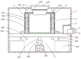
Referring to fig. 1-2, the present invention provides a technical solution: a filter pressing device for sewage treatment comprises a main body box 1, a separating mechanism 2 and a filter pressing mechanism 3, wherein the separating mechanism 2 comprises a supporting plate 201, a treatment cylinder 202, a separating cylinder 203, a motor 204, a speed reducer 205, a rotating shaft 206, a feeding hopper 207 and a filter screen 208, the supporting plate 201 is fixedly connected on the side wall of an inner cavity of the main body box 1, the treatment cylinder 202 is fixedly connected on the top of the supporting plate 201, the motor 204 is arranged in the middle of the bottom of the inner cavity of the main body box 1, the bottom end of the rotating shaft 206 is arranged at the output end of the motor, the top end of the separating cylinder 203 extends to the inner cavity of the processing cylinder 202, the separating cylinder 203 is fixedly connected with the top of a rotating shaft 206, a speed reducer 205 is arranged on the rotating shaft 206, a feed hopper 207 is communicated with the top of the main body box 1, the top of the separating cylinder 203 is provided with an opening 4, and the end of the feed hopper 207 extends above the separation drum 203 through the opening 4, and the filter screen 208 is installed in the inner cavity of the feed hopper 207.
Wherein, the filter pressing mechanism 3 includes first pneumatic cylinder 301, second pneumatic cylinder 302, the clamp plate 303, the filter membrane 304, blow off pipe 305, sludge pump 306 and collecting box 307, first pneumatic cylinder 301 fixed connection is at the top of handling a section of thick bamboo 202 inner chamber, second pneumatic cylinder 302 pegs graft on the backup pad 201, and be located the inner chamber of handling a section of thick bamboo 202, the clamp plate 303 is equipped with the multiunit, and fixed connection is at the output of first pneumatic cylinder 301 and second pneumatic cylinder 302 respectively, filter membrane 304 fixed connection is between two sets of clamp plates 303 of corresponding from top to bottom, the one end intercommunication of blow off pipe 305 is in the below of handling a section of thick bamboo 202, and the other end extends to the below of backup pad 201, sludge pump 306 concatenates on blow off pipe 305, and be located the top of backup pad 201, collecting box 307 sets up the bottom in 1 inner chamber of main part case.
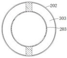
Wherein, the sidewall of the separating cylinder 203 is provided with a first through hole 5, and the sidewall of the treating cylinder 202 is provided with a second through hole 6.
The pressure plate 303 is arc-shaped, the size of the pressure plate 303 is matched with the size of a gap between the separation cylinder 203 and the treatment cylinder 202, and the first through hole 5 and the second through hole 6 are positioned between the two groups of pressure plates 303.
Wherein, the outside of main part case 1 still communicates there is drain pipe 7, and the position that main part case 1 inner chamber is close to drain pipe 7 is equipped with filter mantle 8, and the end of drain pipe 7 is installed control valve 9.
One specific application of this embodiment is: the device supplies electric energy to electrical elements in the device through an external power supply and controls the on-off of the electrical elements through a control switch;
when the device is used, sewage is injected from the feed hopper, and is primarily filtered by the filter screen 208, larger impurities are blocked on the filter screen 208 and can be directly cleaned, after the sewage falls into the separation cylinder 203, the motor 204 is turned on, the motor 204 drives the rotating shaft 206 to rotate, so that the separation cylinder 203 rotates in the treatment cylinder 202, the sewage gradually enters the treatment cylinder 202 from the first through hole 5 through centrifugal force, the first hydraulic cylinder 301 and the second hydraulic cylinder 302 are then opened, the pressing plates 303 arranged up and down gradually approach each other, and the filter membrane 304 contracts, so that moisture in the sludge is extruded out, the extruded moisture flows out through the second through hole 6 and finally converges on the supporting plate 201, finally, the control valve 9 is opened, the water is finally filtered by the filter cover 8, the water is led out from the drain pipe 7, after the second hydraulic cylinder 302 is reset, the sludge falls on the pressing plate 303 above the second hydraulic cylinder, and the sludge pump 306 is opened, the sludge is pumped into a collecting tank 307 for collection and then centralized treatment.
In the embodiment of the above-mentioned column 2,
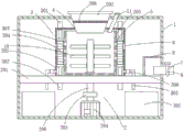
referring to fig. 2-3, embodiment 2 differs from embodiment 1 in that:
wherein, the rotating shaft 206 extends to the inner cavity of the separating cylinder 203, the outer side of the rotating shaft 206 is provided with a stirring shaft 10, and the stirring shaft 10 is provided with a plurality of groups.
Wherein, the top of main part case 1 is equipped with liquid medicine mouth 11, and the end of liquid medicine mouth 11 extends to the top of knockout drum 203, can get rid of the harmful substance in the mud, adds the medicament that can decompose harmful substance in the mud, avoids the harmful substance secondary pollution environment in the mud.
In the description herein, references to the description of "one embodiment," "an example," "a specific example," etc., mean that a particular feature, structure, material, or characteristic described in connection with the embodiment or example is included in at least one embodiment or example of the invention. In this specification, the schematic representations of the terms used above do not necessarily refer to the same embodiment or example. Furthermore, the particular features, structures, materials, or characteristics described may be combined in any suitable manner in any one or more embodiments or examples.
The preferred embodiments of the present invention disclosed above are intended only to help illustrate the present invention. The preferred embodiments are not intended to be exhaustive or to limit the invention to the precise embodiments disclosed. Obviously, many modifications and variations are possible in light of the above teaching. The embodiments were chosen and described in order to best explain the principles of the invention and its practical applications, to thereby enable others skilled in the art to best understand the invention for and utilize the invention. The present invention is limited only by the claims and their full scope and equivalents.
Claims (5)
1. The utility model provides a filter pressing device for sewage treatment which characterized in that: comprises a main body box (1), a separating mechanism (2) and a filter pressing mechanism (3), wherein the separating mechanism (2) comprises a supporting plate (201), a treatment cylinder (202), a separating cylinder (203), a motor (204), a speed reducer (205), a rotating shaft (206), a feeding hopper (207) and a filter screen (208), the supporting plate (201) is fixedly connected on the side wall of the inner cavity of the main body box (1), the treatment cylinder (202) is fixedly connected at the top of the supporting plate (201), the motor (204) is installed at the middle position of the bottom of the inner cavity of the main body box (1), the bottom end of the rotating shaft (206) is installed at the output end of the motor (204), the top end of the rotating shaft extends to the inner cavity of the treatment cylinder (202), the separating cylinder (203) is fixedly connected at the top of the rotating shaft (206), the speed reducer (205) is installed on the rotating shaft (206), the feeding hopper (207, the top of separating cylinder (203) is equipped with opening (4), and the end of feeder hopper (207) extends to the top of separating cylinder (203) through opening (4), filter screen (208) are installed in the inner chamber of feeder hopper (207).
2. A filter-press apparatus as defined in claim 1 for wastewater treatment, wherein: the filter pressing mechanism (3) comprises a first hydraulic cylinder (301), a second hydraulic cylinder (302), a pressing plate (303), a filter membrane (304), a sewage discharge pipe (305), a sludge pump (306) and a collecting box (307), wherein the first hydraulic cylinder (301) is fixedly connected to the top of the inner cavity of the treatment barrel (202), the second hydraulic cylinder (302) is inserted into the supporting plate (201) and is positioned in the inner cavity of the treatment barrel (202), the pressing plate (303) is provided with a plurality of groups and is respectively and fixedly connected to the output ends of the first hydraulic cylinder (301) and the second hydraulic cylinder (302), the filter membrane (304) is fixedly connected between two groups of pressing plates (303) which correspond up and down, one end of the sewage discharge pipe (305) is communicated below the treatment barrel (202), the other end of the sewage discharge pipe extends to the lower part of the supporting plate (201), the sludge pump (306) is connected in series to the sewage discharge pipe (305) and is positioned above the supporting plate (, the collecting box (307) is arranged at the bottom of the inner cavity of the main body box (1) and is positioned below the tail end of the sewage draining pipe (305).
3. A filter-press apparatus as defined in claim 2 for wastewater treatment, wherein: the side wall of the separation barrel (203) is provided with a first through hole (5), and the side wall of the treatment barrel (202) is provided with a second through hole (6).
4. A filter-press apparatus as claimed in claim 3 for wastewater treatment, wherein: the pressing plate (303) is arc-shaped, the size of the pressing plate (303) is matched with the size of a gap between the separating cylinder (203) and the treating cylinder (202), and the first through hole (5) and the second through hole (6) are positioned between the two groups of pressing plates (303).
5. A filter-press apparatus as defined in claim 1 for wastewater treatment, wherein: the outer side of the main body box (1) is also communicated with a drain pipe (7), a filter cover (8) is arranged at the position, close to the drain pipe (7), of the inner cavity of the main body box (1), and a control valve (9) is installed at the tail end of the drain pipe (7).
Priority Applications (1)
| Application Number | Priority Date | Filing Date | Title |
|---|---|---|---|
| CN202020608000.0U CN212491919U (en) | 2020-04-22 | 2020-04-22 | A filter pressing device for sewage treatment |
Applications Claiming Priority (1)
| Application Number | Priority Date | Filing Date | Title |
|---|---|---|---|
| CN202020608000.0U CN212491919U (en) | 2020-04-22 | 2020-04-22 | A filter pressing device for sewage treatment |
Publications (1)
| Publication Number | Publication Date |
|---|---|
| CN212491919U true CN212491919U (en) | 2021-02-09 |
Family
ID=74435289
Family Applications (1)
| Application Number | Title | Priority Date | Filing Date |
|---|---|---|---|
| CN202020608000.0U Active CN212491919U (en) | 2020-04-22 | 2020-04-22 | A filter pressing device for sewage treatment |
Country Status (1)
| Country | Link |
|---|---|
| CN (1) | CN212491919U (en) |
Cited By (1)
| Publication number | Priority date | Publication date | Assignee | Title |
|---|---|---|---|---|
| CN113350875A (en) * | 2021-05-10 | 2021-09-07 | 杭州国泰环保科技股份有限公司 | Sludge dewatering residue purifying and filtering equipment |
-
2020
- 2020-04-22 CN CN202020608000.0U patent/CN212491919U/en active Active
Cited By (1)
| Publication number | Priority date | Publication date | Assignee | Title |
|---|---|---|---|---|
| CN113350875A (en) * | 2021-05-10 | 2021-09-07 | 杭州国泰环保科技股份有限公司 | Sludge dewatering residue purifying and filtering equipment |
Similar Documents
| Publication | Publication Date | Title |
|---|---|---|
| CN105819638B (en) | High mass dryness fraction sewage sludge treatment method | |
| CN106865941A (en) | A kind of centrifugal dewatering of sludge processing unit | |
| CN109912083B (en) | Electrochemical detoxification and deep dehydration method for blue algae liquid | |
| CN104496146A (en) | Sludge dewatering machine | |
| CN215627518U (en) | Excrement and urine professional processing apparatus of animal husbandry industry | |
| CN212491919U (en) | A filter pressing device for sewage treatment | |
| CN105819637B (en) | High mass dryness fraction sewage sludge processing unit | |
| CN209383637U (en) | A kind of sewage disposal device silt cleaning device | |
| CN105363254A (en) | Garbage leachate filter | |
| CN210437827U (en) | Garbage recycling device | |
| CN216941935U (en) | Municipal administration discarded object solid-liquid filtering separation device | |
| CN105819640B (en) | Gas aoxidizes sewage sludge multistage dewatering | |
| CN215756976U (en) | Sludge deep dehydration processing system | |
| CN212894226U (en) | Rural area rubbish sewage treatment device | |
| CN105948301B (en) | High mass dryness fraction sewage sludge integrated sewage treatment system and method | |
| CN105819636B (en) | High mass dryness fraction sewage sludge treatment system | |
| CN210825902U (en) | Sludge drying system and equipment | |
| CN210974374U (en) | Municipal works sludge treatment equipment | |
| CN210796154U (en) | Sludge concentration dewatering device for sewage treatment | |
| CN209890448U (en) | Pig raising wastewater treatment system | |
| CN210085229U (en) | Cathode and pressing belt integrated sludge electroosmosis belt type filter pressing device | |
| CN209906537U (en) | Deep dehydration device for blue algae | |
| CN113603329A (en) | Method for wastewater treatment and sludge reduction | |
| CN105819639B (en) | Gas aoxidizes sewage sludge multistage dehydration device | |
| CN206232577U (en) | The rotary sewage-treatment plant of roller |
Legal Events
| Date | Code | Title | Description |
|---|---|---|---|
| GR01 | Patent grant | ||
| GR01 | Patent grant |