CN212478941U - High-performance airtight sliding window - Google Patents
High-performance airtight sliding window Download PDFInfo
- Publication number
- CN212478941U CN212478941U CN202020693434.5U CN202020693434U CN212478941U CN 212478941 U CN212478941 U CN 212478941U CN 202020693434 U CN202020693434 U CN 202020693434U CN 212478941 U CN212478941 U CN 212478941U
- Authority
- CN
- China
- Prior art keywords
- sealing rubber
- rubber strip
- frame
- wall
- strip
- Prior art date
- Legal status (The legal status is an assumption and is not a legal conclusion. Google has not performed a legal analysis and makes no representation as to the accuracy of the status listed.)
- Active
Links
Images
Landscapes
- Specific Sealing Or Ventilating Devices For Doors And Windows (AREA)
Abstract
The utility model discloses a high-performance airtight sliding window, a sealing rubber strip I (10) and a sealing rubber strip II (12) are respectively arranged between the upper part and the middle part of a sliding rail section bar I (6) and the inner wall of an upper inner track I (8), a sealing rubber strip III (14) and a sealing rubber strip IV (16) are respectively arranged between the middle part and the lower part of a sliding rail section bar II (7) and the inner wall of a lower inner track I (9), a sealing rubber strip V (24) and a sealing rubber strip VI (26) are respectively arranged between the upper part and the middle part of a sliding rail section bar III (20) and the inner wall of an upper outer track I (22), a sealing rubber strip V (28) and a sealing rubber strip VIII (30) are respectively arranged between the middle part and the lower part of a sliding rail section bar IV (21) and the inner wall of a lower outer track I (23), a left mounting groove combination is arranged on the left inner wall of an outer window frame (3), a sealing, and a sealing rubber strip combination II is arranged in the right mounting groove combination.
Description
Technical Field
The utility model relates to an airtight austral window, sliding sash of high performance.
Background
The sealing part of present sliding window generally adopts the wool top, and this kind of wool top is sealed can all be inefficacy after using five years, leads to the unable normal use of austral window, sliding sash, and life is short, and this wool top is in the back that inefficacy moreover, can't realize waterproofly meeting under heavy rain, heavy rain or the condition that rivers are more urgent, and user oneself also can't directly change, need lead to using and maintaining very inconvenient.
Disclosure of Invention
The utility model provides an airtight austral window, sliding sash of high performance, it is not only sealing performance good to improve life, easy maintenance moreover.
The utility model adopts the following technical scheme: a high-performance airtight sliding window is provided with a left inner window, a right outer window and an outer window frame, wherein the left inner window and the right outer window are positioned in the outer window frame, the left inner window is provided with a left frame, a left window sash is installed in the left frame, the upper part and the lower part of the left frame are respectively provided with a sliding rail section I and a sliding rail section II, the sliding rail section I is positioned in an upper inner rail I arranged on the inner side of the upper part of the outer window frame, the sliding rail section II is positioned in a lower inner rail I arranged on the inner side of the lower part of the outer window frame, and the upper part and the lower part of the left frame respectively move along the upper; a sealing rubber strip I is arranged between the upper part of the sliding rail section bar I and the inner wall of the upper inner rail I, the sealing rubber strip I is arranged in a mounting groove I formed in the inner wall of the upper inner rail I, a sealing rubber strip II is arranged between the middle part of the sliding rail section bar I and the inner wall of the upper inner rail I, and the sealing rubber strip II is arranged in a mounting groove II formed in the inner wall of the upper inner rail I; a sealing rubber strip III is arranged between the middle part of the sliding rail section II and the inner wall of the lower inner rail I, the sealing rubber strip III is arranged in a mounting groove III formed in the inner wall of the lower inner rail I, a sealing rubber strip IV is arranged between the lower part of the sliding rail section II and the inner wall of the lower inner rail I, and the sealing rubber strip IV is arranged in a mounting groove IV formed in the inner wall of the lower inner rail I; the right outer window is provided with a right frame, a right window sash is installed in the right frame, the upper portion and the lower portion of the right frame are respectively provided with a slide rail section bar III and a slide rail section bar IV, the slide rail section bar III is positioned in an upper outer rail I arranged on the outer side of the upper portion of the outer window frame, the slide rail section bar IV is positioned in a lower outer rail I arranged on the outer side of the lower portion of the outer window frame, and the upper portion and the lower portion of the right frame respectively move along the upper outer rail I and the lower outer; a sealing rubber strip V is arranged between the upper part of the slide rail section bar III and the inner wall of the upper outer rail I, the sealing rubber strip V is arranged in a mounting groove V formed in the inner wall of the upper outer rail I, a sealing rubber strip VI is arranged between the middle part of the slide rail section bar III and the inner wall of the upper outer rail I, and the sealing rubber strip VI is arranged in a mounting groove VI formed in the inner wall of the upper outer rail I; a sealing rubber strip VII is arranged between the middle part of the slide rail section bar IV and the inner wall of the lower outer rail I, the sealing rubber strip VII is arranged in a mounting groove VII arranged on the inner wall of the lower outer rail I, a sealing rubber strip VIII is arranged between the lower part of the slide rail section bar IV and the inner wall of the lower outer rail I, the sealing rubber strip VIII is arranged in a mounting groove VIII arranged on the inner wall of the lower outer rail I, a left mounting groove combination is arranged on the inner wall of the left side of the outer window frame, a sealing rubber strip combination I is arranged in the left mounting groove combination, when the left side of a left frame is contacted with the inner wall of the left side of the outer window frame, the sealing rubber strip combination I is positioned between the left side of a left frame and the inner wall of the left side of the outer window frame, a right mounting groove combination is arranged on the inner wall of the right side of the outer window frame, a sealing rubber strip combination II is arranged in the, the right side of left side frame be equipped with middle mounting groove combination, install joint strip combination III in middle mounting groove combination, when the right side of left side frame overlaps with the left side of right side frame, joint strip combination III is located between the right side of left side frame and the left side of right frame.
The sealing rubber strip I and the sealing rubber strip II are both ethylene propylene diene monomer rubber strips. And the sealing rubber strip III and the sealing rubber strip IV are both set to be ethylene propylene diene monomer rubber strips. The sealing rubber strip V and the sealing rubber strip VI are both set as ethylene-propylene-diene monomer rubber strips. And the sealing rubber strip VII and the sealing rubber strip VIII are both set as ethylene-propylene-diene rubber strips. Left side mounting groove combination include two parallel notch I and notch II, notch I and notch II distribute on the left inner wall of outer window frame, joint strip combination I include joint strip IX and joint strip X, joint strip IX imbeds in notch I, joint strip X imbeds in notch II, wherein when the left side of left side frame and the left inner wall contact of outer window frame, joint strip IX and notch I are located the clearance that left side frame left side was equipped with, joint strip X and notch II are located the left side frame outsidely, joint strip IX and joint strip X all set up to ethylene propylene diene monomer strip.
Right mounting groove combination include two parallel notches III and notch IV, notch III and notch IV distribute on the inner wall on outer window frame right side, joint strip combination II include joint strip XI and joint strip XII, joint strip XI imbeds in notch III, joint strip XII imbeds in the notch IV, wherein when the right side of right side frame and the inner wall contact on outer window frame right side, joint strip XI and notch III are located the clearance that right frame right side was equipped with, joint strip XII and notch IV are located the right frame outside, joint strip XI and joint strip XII set up to the ethylene propylene diene monomer adhesive tape.
Middle mounting groove combination include notch V and notch VI, notch V and notch VI symmetric distribution are on the right side of left side frame, joint strip combination III includes joint strip A and joint strip B, joint strip A is located notch V, joint strip B is located notch VI, when the right side of left side frame overlaps with the left side of right side frame, joint strip A and joint strip B are located between the right side of left side frame and the left side of right frame, joint strip A and joint strip B are relative with the left side of right frame, joint strip A and joint strip B all set up to the EPT rubber strip. A partition plate is arranged between the lower inner rail I and the lower outer rail I, an inner drain hole is formed in the partition plate, an outer drain hole is formed in one outdoor side of the lower portion of the outer window frame, and the position of the inner drain hole is higher than that of the outer drain hole.
The utility model discloses following beneficial effect has: after having adopted above technical scheme, the utility model discloses not only can improve the sealing performance of sliding window through the joint strip that is equipped with in each position to can prevent effectively that water from flowing into from outdoor indoorly, improve sealing performance, moreover the utility model discloses a joint strip all be the EPT adhesive tape of adoption, this adhesive tape is long service life not only, and is sealed effectual moreover. The utility model discloses a joint strip is not directly pasting on left interior window, right outer window and outer window frame, places joint strip in the mounting groove moreover, can be convenient for like this change, use and easy maintenance. The utility model discloses be equipped with baffle 44 down between interior track I and the outer track I, be equipped with interior wash port on the baffle, be located outdoor one side and be equipped with outer drainage hole in outer window frame lower part, the position of interior wash port is higher than outer drainage's position, can leak indoor rainwater like this and discharge through interior wash port and outer drainage hole, has further improved sealing performance.
Drawings
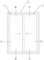
Fig. 1 is a schematic diagram of the external structure of the present invention.
Fig. 2 is a sectional view a-a of fig. 1.
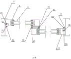
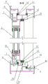
Fig. 3 is a sectional view B-B of fig. 1.
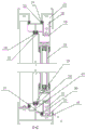
Fig. 4 is a cross-sectional view taken along line C-C of fig. 1.
Detailed Description
In fig. 1, the utility model provides a high performance airtight sliding window, it is equipped with left interior window 1, right exterior window 2 and outer window frame 3, left interior window 1 and right outer window 2 are located outer window frame 3, in fig. 3, left interior window 1 be equipped with left side frame 4, install left casement 5 in left side frame 4, the upper portion and the lower part of left side frame 4 are slide rail section bar i 6 and slide rail section bar ii 7 respectively, slide rail section bar i 6 is located the upper interior track i 8 that outer window frame 3 upper portion inboard was equipped with, slide rail section bar ii 7 is located the lower interior track i 9 that outer window frame 3 lower part inboard was equipped with, the upper portion and the lower part of left side frame 4 move along upper interior track i 8 and lower interior track i 9 respectively; a sealing rubber strip I10 is arranged between the upper part of the sliding rail section bar I6 and the inner wall of the upper inner rail I8, the sealing rubber strip I10 is arranged in a mounting groove I11 formed in the inner wall of the upper inner rail I8, a sealing rubber strip II 12 is arranged between the middle part of the sliding rail section bar I6 and the inner wall of the upper inner rail I8, the sealing rubber strip II 12 is arranged in a mounting groove II 13 formed in the inner wall of the upper inner rail I8, and the sealing rubber strip I10 and the sealing rubber strip II 12 are both ethylene propylene diene monomer rubber strips; a sealing rubber strip III 14 is arranged between the middle part of the sliding rail section II 7 and the inner wall of the lower inner rail I9, the sealing rubber strip III 14 is installed in an installation groove III 15 formed in the inner wall of the lower inner rail I9, a sealing rubber strip IV 16 is arranged between the lower part of the sliding rail section II 7 and the inner wall of the lower inner rail I9, the sealing rubber strip IV 16 is installed in an installation groove IV 17 formed in the inner wall of the lower inner rail I9, and the sealing rubber strip III 14 and the sealing rubber strip IV 16 are both ethylene propylene diene monomer rubber strips; in fig. 4, the right outer window 2 is provided with a right frame 18, a right window sash 19 is installed in the right frame 18, the upper part and the lower part of the right frame 18 are respectively a sliding rail section bar iii 20 and a sliding rail section bar iv 21, the sliding rail section bar iii 20 is positioned in an upper outer rail i 22 arranged on the outer side of the upper part of the outer window frame 3, the sliding rail section bar iv 21 is positioned in a lower outer rail i 23 arranged on the outer side of the lower part of the outer window frame 3, and the upper part and the lower part of the right frame 18 respectively move along the upper outer rail i 22 and the lower outer rail i 23; a sealing rubber strip V24 is arranged between the upper part of the sliding rail section bar III 20 and the inner wall of the upper outer rail I22, the sealing rubber strip V24 is arranged in a mounting groove V25 formed in the inner wall of the upper outer rail I22, a sealing rubber strip VI 26 is arranged between the middle part of the sliding rail section bar III 20 and the inner wall of the upper outer rail I22, and the sealing rubber strip VI 26 is arranged in a mounting groove VI 27 formed in the inner wall of the upper outer rail I22; the sealing rubber strip V24 and the sealing rubber strip VI 26 are both ethylene propylene diene monomer rubber strips, a sealing rubber strip VII 28 is arranged between the middle of the slide rail section IV 21 and the inner wall of the lower outer rail I23, the sealing rubber strip VII 28 is installed in an installation groove VII 29 formed in the inner wall of the lower outer rail I23, a sealing rubber strip VIII 30 is arranged between the lower portion of the slide rail section IV 21 and the inner wall of the lower outer rail I23, the sealing rubber strip VIII 30 is installed in an installation groove VIII 31 formed in the inner wall of the lower outer rail I23, the sealing rubber strip VII 28 and the sealing rubber strip VIII 30 are both ethylene propylene diene monomer rubber strips, a partition plate 44 is arranged between the lower inner rail I9 and the lower outer rail I23, an inner drainage hole 45 is formed in the partition plate 44, an outer drainage hole 46 is formed in one outdoor side of the lower portion of the outer window frame 3, and the position of the inner drainage hole 45 is higher than the position of. In fig. 2, a left mounting groove assembly is formed on the inner wall of the left side of the outer window frame 3, a sealant strip assembly i is mounted in the left mounting groove assembly, when the left side of the left frame 4 contacts the inner wall of the left side of the outer window frame 3, the sealant strip assembly i is located between the left side of the left frame 4 and the inner wall of the left side of the outer window frame 3, the left mounting groove assembly comprises two parallel notches i 32 and ii 33, the notches i 32 and ii 33 are distributed on the inner wall of the left side of the outer window frame 3, the sealant strip assembly i comprises a sealant strip ix 34 and a sealant strip x 35, the sealant strip ix 34 is inserted into the notch i 32, the sealant strip x 35 is inserted into the notch ii 33, wherein when the left side of the left frame 4 contacts the inner wall of the left side of the outer window frame 3, the sealant strip ix 34 and the notch i 32 are located in a gap formed on the left side of the left frame 4, and the sealant strip x 35 and ii, sealing rubber strips IX 34 and X35 are both set as ethylene-propylene-diene monomer rubber strips, the right mounting groove combination is arranged on the inner wall of the right side of the outer window frame 3, a sealing rubber strip combination II is arranged in the right mounting groove combination, when the right side of the right frame 18 is in contact with the inner wall of the right side of the outer window frame 3, the sealing rubber strip combination II is positioned between the right side of the right frame 18 and the inner wall of the right side of the outer window frame 3, the right mounting groove combination comprises two parallel notches III 36 and IV 37, the notches III 36 and IV 37 are distributed on the inner wall of the right side of the outer window frame 3, the sealing rubber strip combination II comprises a sealing rubber strip XI 38 and a sealing rubber strip XII 39, the sealing rubber strip XI 38 is embedded into the notch III 36, the sealing rubber strip XII 39 is embedded into the notch IV 37, wherein when the right side of the right frame 4 is in contact with the inner wall of the right side of the outer window frame 3, sealing rubber strip XII 39 and notch IV 37 are located outside right frame 4, and sealing rubber strip XI 38 and sealing rubber strip XII 39 are set to be ethylene propylene diene monomer rubber strips; the right side of the left frame 4 is provided with a middle mounting groove combination, a sealing rubber strip combination III is arranged in the middle mounting groove combination, when the right side of the left frame 4 is overlapped with the left side of the right frame 18, the joint strip assembly III is positioned between the right side of the left frame 4 and the left side of the right frame 18, the middle mounting groove combination comprises a notch V40 and a notch VI 41, the notch V40 and the notch VI 41 are symmetrically distributed on the right side of the left frame 4, the sealing rubber strip combination III comprises a sealing rubber strip A42 and a sealing rubber strip B43, the sealing rubber strip A42 is positioned in the notch V40, the sealing rubber strip B43 is positioned in the notch VI 41, when the right side of the left frame 4 overlaps the left side of the right frame 18, the sealant a42 and the sealant B43 are located between the right side of the left frame 4 and the left side of the right frame 18, the sealant a42 and the sealant B43 are opposite to the left side of the right frame 4, and the sealant a42 and the sealant B43 are both ethylene propylene diene monomer (epdm) sealants.
The sealing rubber strip I10 of the utility model is arranged in the mounting groove I11 arranged on the inner wall of the upper inner track I8, so that the sealing rubber strip I10 can be directly taken out from the mounting groove I11 for direct replacement after being damaged; the sealing rubber strip II 12 is arranged in a mounting groove II 13 formed in the inner wall of the upper inner rail I8, so that the sealing rubber strip II 12 can be directly taken out of the mounting groove II 13 to be directly replaced after being damaged; the sealing rubber strip III 14 is arranged in a mounting groove III 15 formed in the inner wall of the lower inner rail I9, so that the sealing rubber strip III 14 can be directly taken out of the mounting groove III 15 to be directly replaced after being damaged; the sealing rubber strip IV 16 is arranged in a mounting groove IV 17 formed in the inner wall of the lower inner rail I9, so that the sealing rubber strip IV 16 can be directly taken out of the mounting groove IV 17 to be directly replaced after being damaged; the sealing rubber strip V24 is arranged in a mounting groove V25 formed in the inner wall of the upper outer track I22, so that the sealing rubber strip V24 can be directly taken out of the mounting groove V25 to be directly replaced after being damaged; the sealing rubber strip VI 26 is arranged in a mounting groove VI 27 arranged on the inner wall of the upper outer rail I22, so that the sealing rubber strip VI 26 can be directly taken out from the mounting groove VI 27 for direct replacement after being damaged; the sealing rubber strip VII 28 is arranged in an installation groove VII 29 formed in the inner wall of the lower outer rail I23, so that the sealing rubber strip VII 28 can be directly taken out of the installation groove VII 29 for direct replacement after being damaged; the sealing rubber strip VIII 30 is arranged in a mounting groove VIII 31 formed in the inner wall of the lower outer rail I23, so that the sealing rubber strip VIII 30 can be directly taken out of the mounting groove VIII 31 to be directly replaced after being damaged; the sealing rubber strip IX 34 is embedded into the notch I32, and the sealing rubber strip X35 is embedded into the notch II 33, so that the sealing rubber strip IX 34 can be directly taken out of the notch I32 for direct replacement after being damaged, and the sealing rubber strip X35 can be directly taken out of the notch II 33 for direct replacement after being damaged; sealing rubber strip XI 38 is embedded into notch III 36, and sealing rubber strip XII 39 is embedded into notch IV 37, so when the above-mentioned sealing rubber strip XI 38 damages the back can directly be taken out from notch III 36 and directly be changed, sealing rubber strip XII 39 damages the back and directly can be taken out from notch IV 37 and directly be changed; sealing rubber strip A42 is located notch V40, and sealing rubber strip B43 is located notch VI 41, can directly take out direct the change in notch V40 after above-mentioned sealing rubber strip A42 damages like this, can directly take out direct the change in notch VI 41 after sealing rubber strip B43 damages. The utility model discloses be equipped with baffle 44 down between I9 of interior track and the outer track I23 down, be equipped with interior wash port 45 on baffle 44, be located outdoor one side and be equipped with outer wash port 46 in the 3 lower parts of outer window frame, interior wash port 45's position is higher than outer wash port 46's position, can leak indoor rainwater like this and discharge through interior wash port 45 and outer wash port 46, has further improved sealing performance.
Claims (9)
1. A high-performance airtight sliding window is characterized by being provided with a left inner window (1), a right outer window (2) and an outer window frame (3), wherein the left inner window (1) and the right outer window (2) are positioned in the outer window frame (3), the left inner window (1) is provided with a left frame (4), a left window sash (5) is installed in the left frame (4), the upper portion and the lower portion of the left frame (4) are respectively provided with a sliding rail section bar I (6) and a sliding rail section bar II (7), the sliding rail section bar I (6) is positioned in an upper inner rail I (8) arranged on the inner side of the upper portion of the outer window frame (3), the sliding rail section bar II (7) is positioned in a lower inner rail I (9) arranged on the inner side of the lower portion of the outer window frame (3), and the upper portion and the lower portion of the left frame (4) respectively move along the upper inner rail I; a sealing rubber strip I (10) is arranged between the upper portion of a sliding rail section bar I (6) and the inner wall of an upper inner rail I (8), the sealing rubber strip I (10) is installed in a mounting groove I (11) formed in the inner wall of the upper inner rail I (8), a sealing rubber strip II (12) is arranged between the middle portion of the sliding rail section bar I (6) and the inner wall of the upper inner rail I (8), the sealing rubber strip II (12) is installed in a mounting groove II (13) formed in the inner wall of the upper inner rail I (8), a sealing rubber strip III (14) is arranged between the middle portion of the sliding rail section bar II (7) and the inner wall of a lower inner rail I (9), the sealing rubber strip III (14) is installed in a mounting groove III (15) formed in the inner wall of the lower inner rail I (9), a sealing rubber strip IV (16) is arranged between the lower portion of the sliding rail section bar II (7) and the inner wall of the lower inner rail I (9), and the sealing rubber strip IV (16) is installed in a, the right outer window (2) is provided with a right frame (18), a right window sash (19) is installed in the right frame (18), the upper portion and the lower portion of the right frame (18) are respectively provided with a sliding rail section bar III (20) and a sliding rail section bar IV (21), the sliding rail section bar III (20) is positioned in an upper outer rail I (22) arranged on the outer side of the upper portion of the outer window frame (3), the sliding rail section bar IV (21) is positioned in a lower outer rail I (23) arranged on the outer side of the lower portion of the outer window frame (3), and the upper portion and the lower portion of the right frame (18) respectively move along the upper outer rail I (22) and the lower outer rail I (23); a sealing rubber strip V (24) is arranged between the upper part of the slide rail section bar III (20) and the inner wall of the upper outer rail I (22), the sealing rubber strip V (24) is arranged in a mounting groove V (25) formed in the inner wall of the upper outer rail I (22), a sealing rubber strip VI (26) is arranged between the middle part of the slide rail section bar III (20) and the inner wall of the upper outer rail I (22), and the sealing rubber strip VI (26) is arranged in a mounting groove VI (27) formed in the inner wall of the upper outer rail I (22); a sealing rubber strip VII (28) is arranged between the middle part of the slide rail section bar IV (21) and the inner wall of the lower outer rail I (23), the sealing rubber strip VII (28) is arranged in a mounting groove VII (29) arranged on the inner wall of the lower outer rail I (23), a sealing rubber strip VIII (30) is arranged between the lower part of the slide rail section bar IV (21) and the inner wall of the lower outer rail I (23), the sealing rubber strip VIII (30) is arranged in a mounting groove VIII (31) arranged on the inner wall of the lower outer rail I (23), a left mounting groove combination I is arranged on the inner wall of the left side of the outer window frame (3), a sealing rubber strip combination I is arranged in the left mounting groove combination, when the left side of the left frame (4) is contacted with the inner wall of the left side of the outer window frame (3), the sealing rubber strip combination I is positioned between the left side of the left frame (4) and the inner wall of the outer window frame (3, install joint strip combination II in the combination of right mounting groove, when the right side of right frame (18) and the inner wall contact on outer window frame (3) right side, joint strip combination II is located between the inner wall on right frame (18) right side and outer window frame (3) right side, the right side of left side frame (4) be equipped with middle mounting groove combination, install joint strip combination III in middle mounting groove combination, when the right side of left side frame (4) and the left side of right frame (18) overlap, joint strip combination III is located between the right side of left side frame (4) and the left side of right frame (18).
2. The high-performance airtight sliding window according to claim 1, wherein said sealing rubber strips I (10) and II (12) are ethylene propylene diene monomer rubber strips.
3. The high-performance airtight sliding window according to claim 1, wherein said sealing rubber strips III (14) and IV (16) are ethylene propylene diene monomer rubber strips.
4. The high-performance airtight sliding window according to claim 1, wherein said sealing rubber strip V (24) and said sealing rubber strip VI (26) are both ethylene propylene diene monomer rubber strips.
5. The high-performance airtight sliding window according to claim 1, wherein said sealing rubber strips VII (28) and VIII (30) are both ethylene propylene diene monomer rubber strips.
6. The high performance airtight sliding window according to claim 1, wherein said left mounting groove assembly comprises two parallel notches I (32) and II (33), the notches I (32) and II (33) are distributed on the inner wall of the left side of the outer sash (3), the sealing rubber strip combination I comprises a sealing rubber strip IX (34) and a sealing rubber strip X (35), the sealing rubber strip IX (34) is embedded into the notch I (32), the sealing rubber strip X (35) is embedded into the notch II (33), wherein when the left side of the left frame (4) contacts the inner wall of the left side of the outer window frame (3), sealing rubber strip IX (34) and notch I (32) are located in the clearance that left side frame (4) left side was equipped with, and sealing rubber strip X (35) and notch II (33) are located left side frame (4) outside, and sealing rubber strip IX (34) and sealing rubber strip X (35) all set up to ethylene propylene diene monomer adhesive tape.
7. The high-performance airtight sliding window according to claim 1, wherein said right mounting groove assembly comprises two parallel notches III (36) and IV (37), the notches III (36) and IV (37) are distributed on the inner wall of the right side of the outer sash (3), the sealing rubber strip combination II comprises a sealing rubber strip XI (38) and a sealing rubber strip XII (39), the sealing rubber strip XI (38) is embedded into the notch III (36), the sealing rubber strip XII (39) is embedded into the notch IV (37), wherein when the right side of the right frame (18) is in contact with the inner wall of the right side of the outer sash (3), sealing rubber strip XI (38) and notch III (36) are located the clearance that right side frame (18) right side was equipped with in, and sealing rubber strip XII (39) and notch IV (37) are located right side frame (18) outside, and sealing rubber strip XI (38) and sealing rubber strip XII (39) set up to ethylene propylene diene monomer adhesive tape.
8. The high-performance airtight sliding window according to claim 1, wherein said middle mounting groove assembly comprises a notch V (40) and a notch VI (41), the notches V (40) and VI (41) are symmetrically distributed on the right side of the left frame (4), the sealant strip assembly III comprises a sealant strip A (42) and a sealant strip B (43), the sealant strip A (42) is located in the notch V (40), the sealant strip B (43) is located in the notch VI (41), when the right side of left frame (4) overlaps with the left side of right frame (18), joint strip A (42) and joint strip B (43) are located between the right side of left frame (4) and the left side of right frame (18), joint strip A (42) and joint strip B (43) are relative with the left side of right frame (18), and joint strip A (42) and joint strip B (43) all set up to ethylene propylene diene monomer adhesive tape.
9. The high-performance airtight sliding window according to claim 1, wherein a partition plate (44) is arranged between the lower inner rail I (9) and the lower outer rail I (23), an inner drainage hole (45) is arranged on the partition plate (44), an outer drainage hole (46) is arranged on the outdoor side of the lower portion of the outer window frame (3), and the position of the inner drainage hole (45) is higher than that of the outer drainage hole (46).
Priority Applications (1)
| Application Number | Priority Date | Filing Date | Title |
|---|---|---|---|
| CN202020693434.5U CN212478941U (en) | 2020-04-30 | 2020-04-30 | High-performance airtight sliding window |
Applications Claiming Priority (1)
| Application Number | Priority Date | Filing Date | Title |
|---|---|---|---|
| CN202020693434.5U CN212478941U (en) | 2020-04-30 | 2020-04-30 | High-performance airtight sliding window |
Publications (1)
| Publication Number | Publication Date |
|---|---|
| CN212478941U true CN212478941U (en) | 2021-02-05 |
Family
ID=74455001
Family Applications (1)
| Application Number | Title | Priority Date | Filing Date |
|---|---|---|---|
| CN202020693434.5U Active CN212478941U (en) | 2020-04-30 | 2020-04-30 | High-performance airtight sliding window |
Country Status (1)
| Country | Link |
|---|---|
| CN (1) | CN212478941U (en) |
Cited By (1)
| Publication number | Priority date | Publication date | Assignee | Title |
|---|---|---|---|---|
| CN111561244A (en) * | 2020-04-30 | 2020-08-21 | 江苏宇马铝业有限公司 | High-performance airtight sliding window |
-
2020
- 2020-04-30 CN CN202020693434.5U patent/CN212478941U/en active Active
Cited By (1)
| Publication number | Priority date | Publication date | Assignee | Title |
|---|---|---|---|---|
| CN111561244A (en) * | 2020-04-30 | 2020-08-21 | 江苏宇马铝业有限公司 | High-performance airtight sliding window |
Similar Documents
| Publication | Publication Date | Title |
|---|---|---|
| WO2016000498A1 (en) | Door or window | |
| CN212478941U (en) | High-performance airtight sliding window | |
| CN111546864A (en) | Vehicle sliding window and vehicle window glass sliding rail thereof | |
| CN111561244A (en) | High-performance airtight sliding window | |
| CN216921862U (en) | Waterproof aluminum alloy door and window | |
| CN215213073U (en) | Alloy door and window with rain and snow leakage prevention function | |
| CN212478936U (en) | Novel high water tightness sliding window structure | |
| CN211230051U (en) | Accessible push-and-pull door is from arranging frame device under water | |
| CN201221283Y (en) | High seal plastic sliding door and window | |
| CN210239528U (en) | Casement system window with invisible drainage function | |
| CN210622645U (en) | Sliding door drainage structures | |
| CN210828872U (en) | High-airtightness side-sliding type sliding window | |
| CN211736849U (en) | Plugging in the middle of the top | |
| CN221002542U (en) | Casement window with hidden hydrophobic structure | |
| CN206503485U (en) | The aluminum wood composite door and window of dual-seal | |
| CN110952884A (en) | Water-draining sound-insulating sliding window | |
| CN215332595U (en) | Inward double-open-net screen window | |
| CN217632013U (en) | High leakproofness keeps warm and insulates against heat type inwardly opened window structure | |
| CN212507945U (en) | Composite sealing fitting for sliding window | |
| CN215718178U (en) | Gliding section bar water retaining and sealing structure of aluminum alloy sliding window | |
| CN214403237U (en) | Novel aluminium system sideslip formula austral window, sliding sash | |
| CN213144217U (en) | Anti-leakage sealing aluminum alloy frame fan | |
| CN221032322U (en) | Section bar overlap joint structure of outer flat-open window | |
| CN215632619U (en) | Sealing structure of window screen integrated casement window | |
| CN219298484U (en) | Waterproof construction at building outer wall top |
Legal Events
| Date | Code | Title | Description |
|---|---|---|---|
| GR01 | Patent grant | ||
| GR01 | Patent grant |