CN212475111U - Mine hoist - Google Patents
Mine hoist Download PDFInfo
- Publication number
- CN212475111U CN212475111U CN202020805819.6U CN202020805819U CN212475111U CN 212475111 U CN212475111 U CN 212475111U CN 202020805819 U CN202020805819 U CN 202020805819U CN 212475111 U CN212475111 U CN 212475111U
- Authority
- CN
- China
- Prior art keywords
- dust
- hopper
- supporting
- feeding
- channel
- Prior art date
- Legal status (The legal status is an assumption and is not a legal conclusion. Google has not performed a legal analysis and makes no representation as to the accuracy of the status listed.)
- Active
Links
Images


Abstract
The utility model provides a mine hoisting machine, which relates to the technical field of hoisting machines, and comprises a supporting base and a supporting frame, wherein the upper end of the supporting frame is provided with a feeding hopper, the inside of the supporting frame is communicated with the feeding hopper and is provided with a feeding channel, one end of the supporting base, which is far away from the supporting frame, is vertically provided with a supporting column, a machine table is arranged between the supporting base and the supporting column, a conveyor belt is arranged on the machine table, a conveying hopper is evenly arranged on the conveyor belt, a dust removing component is arranged above the feeding hopper, and an anti-blocking component is arranged inside the feeding channel, in the utility model, a large amount of dust raised above the feeding hopper is cleaned up through the arrangement of the dust removing component, mineral aggregates in the feeding channel can be evenly stirred and transmitted through the arrangement of the anti-blocking component, the mineral aggregates reaching the conveying hopper from, the problem of raise dust and feedstock channel's jam or pay-off inhomogeneous is solved, the practicality is high.
Description
Technical Field
The utility model relates to a lifting machine technical field especially relates to a mine lifting machine.
Background
The elevator is a large mechanical device which is transported by changing potential energy, and the bucket elevator is used for vertically lifting the lump granular materials such as limestone, coal, gypsum, clinker, dry clay and the like and the powdery materials such as raw materials, cement, coal powder and the like which pass through the crusher.
The ore hoisting machine is important mechanical equipment for transporting mined ores in the mining process, so that the manpower is effectively saved, and the working efficiency can be improved, but at present, because the existing ore hoisting machine is at the position of a feeding port, a large amount of dust is lifted in the feeding process due to the fact that fine dust is mixed in the ores, the health of workers is influenced, and the working efficiency is also influenced; in the process of conveying the ore raw materials to the conveying hopper of the machine station through the feeding channel, the blockage of the feeding channel or uneven feeding can be caused, so that the ore loading capacity on different conveying hoppers is different, and the conveying efficiency is influenced.
SUMMERY OF THE UTILITY MODEL
An object of the utility model is to provide a mine hoisting machine to solve above-mentioned technical problem.
The utility model discloses a solve above-mentioned technical problem, adopt following technical scheme to realize: the utility model provides a mine lifting machine, includes supporting pedestal and braced frame, braced frame is located the left side of supporting pedestal, and braced frame's upper end is provided with the feeder hopper, braced frame's inside is provided with feedstock channel with the feeder hopper intercommunication, support the upper end of base and install first motor, support the vertical support column that is provided with of braced frame's one end, install the board between supporting pedestal and the support column, be provided with the conveyer belt on the board, the conveyer belt cover is on the roller bearing, the output and the roller bearing transmission of first motor are connected, evenly are provided with the transportation hopper on the conveyer belt, the board is kept away from feedstock channel's one end is provided with the discharge hopper, the top of feeder hopper is provided with the dust removal subassembly, feedstock channel.
Preferably, the dust removal subassembly includes the support frame, and the support frame is located the both sides of feeder hopper, and the fixed dust cover that is provided with in upper end of support frame, the upper end of dust cover is provided with the dust storehouse, the dust cover feeds through in the dust storehouse through inhaling the dust pipeline, one side in dust storehouse is provided with the gas vent, and is provided with the filter screen on the gas vent, the inside in dust storehouse is located gas vent position fixed mounting and has negative-pressure air fan, and one side in the dust storehouse far away from the gas vent is provided with the rotation and installs the sealing door, and the upside edge of sealing door is provided with the fixed plate, and fixed plate and dust storehouse lateral wall are provided with the screw, are provided.
Preferably, sealing strips are arranged around the sealing door.
Preferably, prevent stifled subassembly including rotating the axis of rotation of installing in feedstock channel, it has a plurality of stirring boards to distribute along axis annular array in the axis of rotation, install the second motor on feedstock channel's the lateral wall, the input transmission connection of axis of rotation is removed to the output of second motor.
Preferably, a frequency converter is installed on the outer side wall of the feeding channel and electrically connected with the second motor.
Preferably, arc-shaped grooves are formed in two sides of the inner wall of the feeding channel, and the distance between the stirring plate and the arc-shaped grooves is 0.5-0.8 cm.
Preferably, the number of the stirring plates is six, and the size of each stirring plate is the same.
The utility model has the advantages that:
the utility model discloses in through the setting of conveyer belt and transportation hopper, can transport high position department with the ore that is located the low position, setting through the dust removal subassembly, can be with the pay-off in-process, a large amount of dust clean up that raises up above the feeder hopper, avoid the influence healthy to the workman, whole pay-off process is high-efficient going on has also been guaranteed, setting through preventing stifled subassembly, can evenly stir and transmit the mineral aggregate in the feedstock channel, it is even to guarantee to reach the mineral aggregate of transportation hopper from feedstock channel, can be according to the transmission rate of conveyer belt, go the rotational speed of adjusting the second motor, thereby change the transmission rate of mineral aggregate in feedstock channel, whole device simple structure, high durability and convenient operation, can guarantee the fast and stable transportation of ore, the problem of the jam or the pay-off is inhomogeneous of raise dust and feedstock channel has been solved, and the practicality is high.
Drawings
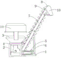
Fig. 1 is a schematic structural diagram of a mine hoist of the present invention;
FIG. 2 is a schematic structural view of the dust-removing assembly and the anti-blocking assembly of the present invention;
FIG. 3 is an enlarged view of part A of FIG. 2 according to the present invention;
FIG. 4 is a schematic view of the three-dimensional structure of the sealing door of the present invention;
reference numerals: 1. a support base; 2. a support frame; 3. a feed hopper; 4. a feed channel; 5. a first motor; 6. a support pillar; 7. a machine platform; 8. a conveyor belt; 9. a transportation hopper; 10. a discharge hopper; 11. a dust removal assembly; 1101. a support frame; 1102. a dust cover; 1103. a dust bin; 1104. an ash suction pipeline; 1105. an exhaust port is arranged; 1106. a filter screen; 1107. a negative pressure fan; 12. an anti-clogging component; 1201. a rotating shaft; 1202. a stirring plate; 1203. a second motor; 13. a sealing door; 14. a fixing plate; 15. a screw hole; 16. and (4) screws.
Detailed Description
In order to make the technical means, the creation features, the achievement purposes and the functions of the present invention easy to understand, the present invention will be further explained below with reference to the following embodiments and the accompanying drawings, but the following embodiments are only the preferred embodiments of the present invention, and not all embodiments are included. Based on the embodiments in the implementation, other embodiments obtained by those skilled in the art without any creative efforts belong to the protection scope of the present invention.
Specific embodiments of the present invention will be described below with reference to the accompanying drawings.
Example 1
As shown in fig. 1-4, a mine hoisting machine, including supporting pedestal 1 and braced frame 2, braced frame 2 is located the left side of supporting pedestal 1, braced frame 2's upper end is provided with feeder hopper 3, braced frame 2's inside and feeder hopper 3 intercommunication are provided with feedstock channel 4, first motor 5 is installed to the upper end of supporting pedestal 1, the vertical support column 6 that is provided with of one end that braced frame 2 was kept away from to supporting pedestal 1, install board 7 between supporting pedestal 1 and the support column 6, be provided with conveyer belt 8 on the board 7, conveyer belt 8 overlaps on the roller bearing, the output and the roller bearing transmission of first motor 5 are connected, evenly be provided with transportation hopper 9 on the conveyer belt 8, the one end that feedstock channel 4 was kept away from to board 7 is provided with discharge hopper 10, the top of feeder hopper 3 is provided with dust removal component 11.
The dust removal assembly 11 comprises a support frame 1101, the support frame 1101 is located on two sides of a feed hopper 3, a dust cover 1102 is fixedly arranged at the upper end of the support frame 1101, a dust bin 1103 is arranged at the upper end of the dust cover 1102, the dust cover 1102 is communicated into the dust bin 1103 through a dust suction pipeline 1104, an exhaust port 1105 is arranged on one side of the dust bin 1103, a filter screen 1106 is arranged on the exhaust port 1105, a negative pressure fan 1107 is fixedly arranged in the exhaust port 1105 and located inside the dust bin 1103, a sealing door 13 is rotatably arranged on one side, away from the exhaust port 1105, of the dust bin 1103, a fixing plate 14 is arranged on the upper side edge of the sealing door 13, screw holes 15 are formed in the outer side walls of the fixing.
Prevent stifled subassembly 12 including rotating the axis of rotation 1201 of installing in feedstock channel 4, it has a plurality of stirring boards 1202 to distribute along axis annular array on the axis of rotation 1201, installs second motor 1203 on feedstock channel 4's the lateral wall, and the output of second motor 1203 goes the input transmission connection of axis of rotation 1201.
The working principle is that in the using process of a mine hoist, crushed ore materials are poured into the feed hopper 3, then the ore can finally reach the conveying hopper 9 on the conveying belt 8 along the feed channel 4, under the driving of the first motor 5, the rollers on the inner sides of the two ends of the conveying belt 8 rotate to drive the conveying belt 8 to rotate in the clockwise direction, low ore forgiveness is transferred to a high position, then the ore is discharged from the discharge hopper 10 to complete the lifting and conveying of the whole ore, in the lifting and conveying process of the whole ore, the dust removal assembly 11 can clear dust above the feed hopper 3, the anti-blocking assembly 12 can roll the ore materials in the feed channel 4, and the feeding is uniform.
In the operation process of the dust removing assembly 11, the negative pressure fan 1107 is turned on, the negative pressure fan 1107 starts to work, so that a negative pressure environment is formed inside the dust bin 1103, dust generated in the feeding hopper 3 in the feeding process can enter the dust suction pipeline 1104 along the dust cover 1102, and finally reaches the dust bin 1103, and gas is discharged from the gas outlet 1105, but the dust can be intercepted by the filter screen 1106, when the dust in the dust bin 1103 is accumulated in a certain amount, the sealing door 13 is opened, the dust collected inside the dust bin 1103 is cleaned out, and then through the matching of the screw hole 15 and the screw 16, the fixing plate 14 at the upper end of the sealing door 13 is tightly fixed on the outer side wall of the dust bin 1103.
Prevent stifled subassembly 12 in the course of the work, second motor 1203 work, it begins to rotate to drive axis of rotation 1201, the last stirring board 1202 of axis of rotation 1201 is to the mineral aggregate in feedstock channel 4 at the uniform velocity stirring, and the rotational speed accessible of axis of rotation 1201 adjusts the rotational speed that the converter controlled second motor 1203, the axis of rotation 1201 of different rotational speeds can drive the different rotational speeds of stirring board 1202, thereby change the output speed of ore raw materials, also be convenient for control the volume of the ore that arrives transportation hopper 9, if when axis of rotation 1201 does not rotate, stirring board 1202 can play fine check effect again, prevent that the mineral aggregate from continuing to discharge from feedstock channel 4.
In the present disclosure, unless expressly stated or limited otherwise, the first feature "on" or "under" the second feature may comprise direct contact between the first and second features, or may comprise contact between the first and second features not directly. Also, the first feature being "on," "above" and "over" the second feature includes the first feature being directly on and obliquely above the second feature, or merely indicating that the first feature is at a higher level than the second feature. A first feature being "under," "below," and "beneath" a second feature includes the first feature being directly under and obliquely below the second feature, or simply meaning that the first feature is at a lesser elevation than the second feature.
The foregoing shows and describes the general principles, essential features, and advantages of the invention. It should be understood by those skilled in the art that the present invention is not limited by the above embodiments, and the description in the above embodiments and the description is only preferred examples of the present invention, and is not intended to limit the present invention, and that the present invention can have various changes and modifications without departing from the spirit and scope of the present invention, and these changes and modifications all fall into the scope of the claimed invention. The scope of the invention is defined by the appended claims and equivalents thereof.
Claims (7)
1. The utility model provides a mine lifting machine, includes support base (1) and braced frame (2), its characterized in that:
the supporting frame (2) is positioned on the left side of the supporting base (1), a feeding hopper (3) is arranged at the upper end of the supporting frame (2), a feeding channel (4) is communicated with the feeding hopper (3) inside the supporting frame (2), a first motor (5) is installed at the upper end of the supporting base (1), a supporting column (6) is vertically arranged at one end, away from the supporting frame (2), of the supporting base (1), a machine table (7) is installed between the supporting base (1) and the supporting column (6), a conveying belt (8) is arranged on the machine table (7), the conveying belt (8) is sleeved on a rolling shaft, the output end of the first motor (5) is in transmission connection with the rolling shaft, a conveying hopper (9) is uniformly arranged on the conveying belt (8), a discharging hopper (10) is arranged at one end, away from the feeding channel (4), of the machine table (7), and a dust removal assembly (11), the feed channel (4) is internally provided with an anti-blocking assembly (12).
2. The mine hoist of claim 1, wherein: the dust removal assembly (11) comprises a support frame (1101), the support frame (1101) is located on two sides of a feed hopper (3), a dust hood (1102) is fixedly arranged at the upper end of the support frame (1101), a dust bin (1103) is arranged at the upper end of the dust hood (1102), the dust hood (1102) is communicated into the dust bin (1103) through a dust suction pipeline (1104), an exhaust port (1105) is formed in one side of the dust bin (1103), a filter screen (1106) is arranged on the exhaust port (1105), a negative pressure fan (1107) is fixedly arranged in the exhaust port (1105) inside the dust bin (1103), a sealing door (13) is rotatably arranged on one side, away from the exhaust port (1105), of the dust bin (1103), a fixing plate (14) is arranged on the upper side edge of the sealing door (13), and screw holes (15) are formed in the outer side walls of the fixing plate (14) and the dust bin (1103, a screw (16) is arranged in the screw hole (15) of the fixing plate (14).
3. The mine hoist of claim 2, wherein: sealing strips are arranged around the sealing door (13).
4. The mine hoist of claim 1, wherein: prevent stifled subassembly (12) including rotating axis of rotation (1201) of installing in feedstock channel (4), it has a plurality of stirring boards (1202) to distribute along axis annular array on axis of rotation (1201), install second motor (1203) on the lateral wall of feedstock channel (4), the input transmission of axis of rotation (1201) is removed to the output of second motor (1203) is connected.
5. The mine hoist of claim 1, wherein: and a frequency converter is arranged on the outer side wall of the feeding channel (4) and is electrically connected with the second motor (1203).
6. The mine hoist of claim 4, wherein: arc grooves are formed in two sides of the inner wall of the feeding channel (4), and the distance between the stirring plate (1202) and the arc grooves is 0.5-0.8 cm.
7. The mine hoist of claim 4, wherein: the stirring plates (1202) are provided with six stirring plates, and the size of each stirring plate (1202) is the same.
Priority Applications (1)
| Application Number | Priority Date | Filing Date | Title |
|---|---|---|---|
| CN202020805819.6U CN212475111U (en) | 2020-05-15 | 2020-05-15 | Mine hoist |
Applications Claiming Priority (1)
| Application Number | Priority Date | Filing Date | Title |
|---|---|---|---|
| CN202020805819.6U CN212475111U (en) | 2020-05-15 | 2020-05-15 | Mine hoist |
Publications (1)
| Publication Number | Publication Date |
|---|---|
| CN212475111U true CN212475111U (en) | 2021-02-05 |
Family
ID=74460915
Family Applications (1)
| Application Number | Title | Priority Date | Filing Date |
|---|---|---|---|
| CN202020805819.6U Active CN212475111U (en) | 2020-05-15 | 2020-05-15 | Mine hoist |
Country Status (1)
| Country | Link |
|---|---|
| CN (1) | CN212475111U (en) |
Cited By (1)
| Publication number | Priority date | Publication date | Assignee | Title |
|---|---|---|---|---|
| CN115338020A (en) * | 2022-07-13 | 2022-11-15 | 安徽省新东方矿业机电股份有限公司 | Scraper loader for mine construction |
-
2020
- 2020-05-15 CN CN202020805819.6U patent/CN212475111U/en active Active
Cited By (1)
| Publication number | Priority date | Publication date | Assignee | Title |
|---|---|---|---|---|
| CN115338020A (en) * | 2022-07-13 | 2022-11-15 | 安徽省新东方矿业机电股份有限公司 | Scraper loader for mine construction |
Similar Documents
| Publication | Publication Date | Title |
|---|---|---|
| CN210279281U (en) | Conveying equipment for refractory material production raw materials | |
| CN206552858U (en) | Constant feeder | |
| CN104909145A (en) | Precise feeding mechanism | |
| CN212475111U (en) | Mine hoist | |
| CN207890716U (en) | A kind of thermal insulation board factory supplies elevator | |
| CN206765104U (en) | Sunk type sandstone blending station | |
| CN212143525U (en) | Mining waste rock discernment sieving mechanism | |
| CN219193576U (en) | Dust suppression and blanking hopper device | |
| CN215086330U (en) | Powder flow controller for adjustable and accurate powder feeding | |
| CN210453260U (en) | Dustproof device of mixing station | |
| CN210366044U (en) | Automatic raw materials dispenser of adjustment gradation | |
| CN211687204U (en) | Conveying mechanism for dry-mixed mortar raw materials | |
| CN210022449U (en) | Novel raw material mill feeding device | |
| CN207714080U (en) | Facilitate the cold burden feeding mechanism of blanking | |
| CN220055609U (en) | Treatment system for conveying sintering raw materials in steel production | |
| CN206840436U (en) | A kind of intelligent heat insulation building block feeding system | |
| CN217650175U (en) | Lifting elevator convenient to high-efficient transport in upper and lower storehouse | |
| CN213894012U (en) | Cement batching material loading lifting machine | |
| CN211306932U (en) | Dry sand lifting and feeding device for dry-mixed mortar production equipment | |
| CN210268161U (en) | Bidirectional belt conveying device for ceramsite | |
| CN215848956U (en) | Dry-mixed mortar raw material hoister | |
| CN220267226U (en) | Building mortar conveying device | |
| CN205471108U (en) | Movable belt conveyer | |
| CN214569117U (en) | Powder conveying system | |
| CN204702170U (en) | Accurate feeding mechanism |
Legal Events
| Date | Code | Title | Description |
|---|---|---|---|
| GR01 | Patent grant | ||
| GR01 | Patent grant |