CN212467582U - Laboratory exhaust treatment device - Google Patents
Laboratory exhaust treatment device Download PDFInfo
- Publication number
- CN212467582U CN212467582U CN202020817034.0U CN202020817034U CN212467582U CN 212467582 U CN212467582 U CN 212467582U CN 202020817034 U CN202020817034 U CN 202020817034U CN 212467582 U CN212467582 U CN 212467582U
- Authority
- CN
- China
- Prior art keywords
- wall
- fixed mounting
- shower
- washing tower
- filter screen
- Prior art date
- Legal status (The legal status is an assumption and is not a legal conclusion. Google has not performed a legal analysis and makes no representation as to the accuracy of the status listed.)
- Expired - Fee Related
Links
Images


Abstract
The utility model discloses a laboratory exhaust treatment device, install fixed block and filter screen through the inner wall at the cover of breathing in, make to insert the filter screen in the fixed block, can carry out the filtration to particle impurity to absorptive gas, make and not contain particle impurity in purification process, make exhaust purification more high-efficient, reduce the damage to purifier, be convenient for wash and change, make the filter screen more reliable and stable, constitute cardboard and draw-in groove for the board stainless steel, can be high temperature resistant and corrosion resistant, it is not fragile when making the filtration. The outer wall fixed mounting at the shower has the shower head, and the shower head is also installed to the washing tower inner wall, and the outer wall fixed mounting of washing tower has water pump and water to drench a tub fixed connection, ensures that all gas all enters into washing, has the stoving layer at the top fixed mounting of shower, and the top fixed mounting on stoving layer has the active carbon to purify the gas that the layer washed with water and dries the repurification, improves the high efficiency of purification.
Description
Technical Field
The utility model relates to a waste gas treatment technical field specifically is a laboratory exhaust treatment device.
Background
The waste gas purification mainly refers to the treatment of industrial waste gas generated in industrial places, such as dust particles, smoke and dust, peculiar smell gas and toxic and harmful gas. Common waste gas purification includes factory smoke waste gas purification, workshop dust waste gas purification, organic waste gas purification, waste gas peculiar smell purification, acid-base waste gas purification and chemical waste gas purification.
Waste gas treatment device in the existing market does not filter when waste gas enters, leads to containing foreign particles in some gases, and the filter screen structure is firm fragile inadequately, and washing in-process gas spills easily, and waste gas washing is incomplete.
To the problem, the utility model provides a laboratory exhaust treatment device.
SUMMERY OF THE UTILITY MODEL
An object of the utility model is to provide a laboratory exhaust treatment device, including aspiration structure and purification structure, aspiration structure fixed mounting has solved the problem that has gaseous spill in the aspiration process at purification structure's outer wall, increases the high efficiency of experiment to the problem in the background art has been solved.
In order to achieve the above object, the utility model provides a following technical scheme: a laboratory waste gas treatment device comprises a gas suction structure and a purification structure, wherein the gas suction structure is fixedly arranged on the outer wall of the purification structure, the gas suction structure is provided with a gas suction cover, a gas suction pipe, an induced draft fan and a motor, one end of the gas suction cover is fixedly provided with the gas suction pipe, one end of the gas suction pipe is fixedly provided with the induced draft fan, and a bearing on one side of the induced draft fan is connected with the motor;
purification structure is provided with washing tower and sewage treatment tank, washing tower fixed mounting is in the upper end of sewage treatment tank, and breathing pipe fixed mounting is in the outer wall and the upper end of washing tower.
Preferably, the inner wall of the air suction cover is provided with a fixed block and a filter screen, and the filter screen is movably connected with the inner side of the fixed block and is of a detachable structure.
Preferably, the filter screen is provided with a clamping plate, a net piece and a clamping groove plate, and the net piece is fixedly connected with the clamping groove plate through the clamping plate.
Preferably, the clamping plate and the clamping groove plate are members made of stainless steel.
Preferably, inside shower, stoving layer and the active carbon purification layer of being provided with of washing tower, the outer wall fixed mounting of shower has the shower, the top fixed mounting of shower has the stoving layer, and the top fixed mounting on stoving layer has the active carbon to purify the layer, and the observation window has been seted up to the outer wall of washing tower, and the outer wall fixed mounting of washing tower has water pump and shower fixed connection.
Compared with the prior art, the beneficial effects of the utility model are as follows:
1. this laboratory exhaust treatment device installs fixed block and filter screen through the inner wall at the cover of breathing in for insert the filter screen in the fixed block, can carry out the filtration to particle impurity to absorbent gas, make and do not contain particle impurity in purification process, make exhaust purification more high-efficient, reduce the damage to purifier, be convenient for wash and change.
2. This laboratory exhaust treatment device is through being provided with cardboard, net piece and draw-in groove board at the filter screen, will net the piece and pass through cardboard and draw-in groove board fixed connection for the filter screen is more reliable and stable, makes cardboard and draw-in groove board stainless steel, can be high temperature resistant corrosion-resistant, and is not fragile when making the filtration.
3. This laboratory exhaust treatment device, there is the shower head through the outer wall fixed mounting at the shower, the shower head is also installed to the washing tower inner wall, the outer wall fixed mounting of washing tower has water pump and shower fixed connection, make gas wash earlier in getting into the washing tower, make waste gas can not discharge through the washing tower inner wall, ensure that all gas all enters into the washing, there is the stoving layer in the top fixed mounting of shower, the top fixed mounting on stoving layer has the active carbon to purify the gas that the layer will wash to dry and repurify, improve the high efficiency of purification, the observation window has been seted up to the outer wall of washing tower, the condition of the inside is observed in real time.
Drawings
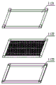
Fig. 1 is a schematic view of the overall structure of the present invention;
FIG. 2 is a schematic view of the structure of the suction cover of the present invention;
FIG. 3 is a schematic view of the filter screen of the present invention;
fig. 4 is a schematic view of the internal structure of the water scrubber of the present invention.
In the figure: 1. a suction structure; 11. an air intake cover; 111. a fixed block; 112. a filter screen; 1121. clamping a plate; 1122. a mesh sheet; 1123. a slot clamping plate; 12. an air intake duct; 13. an induced draft fan; 14. an electric motor; 2. a purification structure; 21. washing the tower with water; 211. a shower pipe; 212. a shower head; 213. drying the layer; 214. an activated carbon purification layer; 215. an observation window; 216. a water pump; 22. a sewage treatment tank.
Detailed Description
The technical solutions in the embodiments of the present invention will be described clearly and completely with reference to the accompanying drawings in the embodiments of the present invention, and it is obvious that the described embodiments are only some embodiments of the present invention, not all embodiments. Based on the embodiments in the present invention, all other embodiments obtained by a person skilled in the art without creative work belong to the protection scope of the present invention.
Referring to fig. 1-4, a laboratory exhaust treatment device comprises an air suction structure 1 and a purification structure 2, wherein the air suction structure 1 is fixedly installed on the outer wall of the purification structure 2.
The air suction structure 1 is provided with an air suction cover 11, an air suction pipe 12, an induced draft fan 13 and a motor 14, one end of the air suction cover 11 is fixedly provided with the air suction pipe 12, one end of the air suction pipe 12 is fixedly provided with the induced draft fan 13, one side bearing of the induced draft fan 13 is connected with the motor 14, the inner wall of the air suction cover 11 is provided with a fixed block 111 and a filter screen 112, the inner wall of the air suction cover 11 is provided with the fixed block 111 and the filter screen 112, so that the filter screen 112 is inserted into the fixed block 111, the absorbed gas can be filtered for particle impurities, the purification process does not contain the particle impurities, the waste gas purification is more efficient, the damage to the purification device is reduced, the cleaning and the replacement are convenient, the filter screen 112 is movably connected on the inner side of the fixed block 111 and is of a detachable structure, the filter screen 112, cardboard 1121 and draw-in groove board 1123 are the component that stainless steel made, and filter screen 112 is provided with cardboard 1121, net piece 1122 and draw-in groove board 1123, passes through cardboard 1121 and draw-in groove board 1123 fixed connection with net piece 1122 for filter screen 112 is more reliable and more stable, constitutes cardboard 1121 and draw-in groove board 1123 with stainless steel, can be high temperature resistant corrosion-resistant, and is not fragile when making the filtration.
The purification structure 2 is provided with a washing tower 21 and a sewage treatment tank 22, the washing tower 21 is fixedly arranged at the upper end of the sewage treatment tank 22, a spray pipe 211, a spray head 212, a drying layer 213 and an active carbon purification layer 214 are arranged inside the washing tower 21, the spray head 212 is fixedly arranged on the outer wall of the spray pipe 211, the drying layer 213 is fixedly arranged above the spray pipe 211, the active carbon purification layer 214 is fixedly arranged above the drying layer 213, an observation window 215 is arranged on the outer wall of the washing tower 21, the spray head 212 is fixedly arranged on the outer wall of the spray pipe 211, the spray head 212 is also arranged on the inner wall of the washing tower 21, a water pump 216 is fixedly arranged on the outer wall of the washing tower 21 and is fixedly connected with the spray pipe 211, so that gas enters the washing tower 21 for washing first time, waste gas cannot be discharged through the inner wall of the washing tower 21, all gas is ensured to be washed, the drying layer 213 is fixedly arranged above the spray pipe 211, the top fixed mounting of stoving layer 213 has activated carbon purification layer 214 to dry the gas of washing and repurify, improves the high efficiency of purification, and observation window 215 has been seted up to the outer wall of washing tower 21, the condition of the inside of real-time observation.
In summary, the following steps: the utility model provides a laboratory waste gas treatment device, which comprises a fixed block 111 and a filter screen 112 which are arranged on the inner wall of an air suction cover 11, the filter screen 112 is inserted into the fixed block 111, the filtering of particle impurities can be carried out on absorbed gas, the purification process is enabled to be free of particle impurities, the waste gas purification is more efficient, the damage to the purification device is reduced, the cleaning and the replacement are convenient, a clamping plate 1121, a net piece 1122 and a clamping groove plate 1123 are arranged on the filter screen 112, the net piece 1122 is fixedly connected with the clamping groove plate 1123 through the clamping plate 1121, the clamping plate 1121 and the clamping groove plate 1123 are parts made of stainless steel, the filter screen 112 is provided with the clamping plate 1121, the net piece 1122 and the clamping groove plate 1123, the net piece 1122 is fixedly connected with the clamping groove plate 1123 through the clamping plate 1121, the filter screen 112 is more stable and reliable, the clamping plate 1121 and the clamping groove plate 1123 are, make not fragile when filtering, there is shower 212 through the outer wall fixed mounting at shower 211, shower 212 is also installed to washing tower 21 inner wall, washing tower 21's outer wall fixed mounting has water pump 216 and shower 211 fixed connection, make gas wash earlier in getting into washing tower 21, make waste gas can not discharge through washing tower 21 inner wall, ensure that all gas all enters the washing, there is stoving layer 213 in the top fixed mounting of shower 211, the top fixed mounting of stoving layer 213 has activated carbon to purify layer 214 and dries the repurifying with the gas that the washing was gone on, improve the high efficiency of purification, observation window 215 has been seted up to washing tower 21's outer wall, the condition of real-time observation the inside.
It is noted that, herein, relational terms such as first and second, and the like may be used solely to distinguish one entity or action from another entity or action without necessarily requiring or implying any actual such relationship or order between such entities or actions. Also, the terms "comprises," "comprising," or any other variation thereof, are intended to cover a non-exclusive inclusion, such that a process, method, article, or apparatus that comprises a list of elements does not include only those elements but may include other elements not expressly listed or inherent to such process, method, article, or apparatus.
Although embodiments of the present invention have been shown and described, it will be appreciated by those skilled in the art that changes, modifications, substitutions and alterations can be made in these embodiments without departing from the principles and spirit of the invention, the scope of which is defined in the appended claims and their equivalents.
Claims (5)
1. The utility model provides a laboratory exhaust treatment device, includes suction structure (1) and purification structure (2), suction structure (1) fixed mounting is at the outer wall of purification structure (2), its characterized in that: the air suction structure (1) is provided with an air suction cover (11), an air suction pipe (12), an induced draft fan (13) and a motor (14), wherein the air suction pipe (12) is fixedly installed at one end of the air suction cover (11), the induced draft fan (13) is fixedly installed at one end of the air suction pipe (12), and a bearing at one side of the induced draft fan (13) is connected with the motor (14);
purification structure (2) are provided with washing tower (21) and sewage treatment tank (22), washing tower (21) fixed mounting is in the upper end of sewage treatment tank (22), and breathing pipe (12) fixed mounting is in the outer wall and the upper end of washing tower (21).
2. The laboratory exhaust treatment device of claim 1, wherein: fixed block (111) and filter screen (112) are installed to the inner wall of cover (11) of breathing in, filter screen (112) are at the inboard swing joint of fixed block (111), and are detachable construction.
3. A laboratory exhaust treatment device according to claim 2, wherein: the filter screen (112) is provided with a clamping plate (1121), a net piece (1122) and a clamping groove plate (1123), and the net piece (1122) is fixedly connected with the clamping groove plate (1123) through the clamping plate (1121).
4. A laboratory exhaust treatment device according to claim 3, wherein: the clamping plate (1121) and the clamping groove plate (1123) are members made of stainless steel materials.
5. The laboratory exhaust treatment device of claim 1, wherein: washing tower (21) inside is provided with shower (211), shower (212), stoving layer (213) and activated carbon purification layer (214), the outer wall fixed mounting of shower (211) has shower (212), the top fixed mounting of shower (211) has stoving layer (213), and the top fixed mounting of stoving layer (213) has activated carbon to purify layer (214), and observation window (215) have been seted up to the outer wall of washing tower (21), and the outer wall fixed mounting of washing tower (21) has water pump (216) and shower (211) fixed connection.
Priority Applications (1)
| Application Number | Priority Date | Filing Date | Title |
|---|---|---|---|
| CN202020817034.0U CN212467582U (en) | 2020-05-17 | 2020-05-17 | Laboratory exhaust treatment device |
Applications Claiming Priority (1)
| Application Number | Priority Date | Filing Date | Title |
|---|---|---|---|
| CN202020817034.0U CN212467582U (en) | 2020-05-17 | 2020-05-17 | Laboratory exhaust treatment device |
Publications (1)
| Publication Number | Publication Date |
|---|---|
| CN212467582U true CN212467582U (en) | 2021-02-05 |
Family
ID=74459699
Family Applications (1)
| Application Number | Title | Priority Date | Filing Date |
|---|---|---|---|
| CN202020817034.0U Expired - Fee Related CN212467582U (en) | 2020-05-17 | 2020-05-17 | Laboratory exhaust treatment device |
Country Status (1)
| Country | Link |
|---|---|
| CN (1) | CN212467582U (en) |
Cited By (1)
| Publication number | Priority date | Publication date | Assignee | Title |
|---|---|---|---|---|
| CN113599954A (en) * | 2021-08-19 | 2021-11-05 | 姚昆省 | Waste gas treatment equipment |
-
2020
- 2020-05-17 CN CN202020817034.0U patent/CN212467582U/en not_active Expired - Fee Related
Cited By (1)
| Publication number | Priority date | Publication date | Assignee | Title |
|---|---|---|---|---|
| CN113599954A (en) * | 2021-08-19 | 2021-11-05 | 姚昆省 | Waste gas treatment equipment |
Similar Documents
| Publication | Publication Date | Title |
|---|---|---|
| CN212467582U (en) | Laboratory exhaust treatment device | |
| CN212431173U (en) | Air purification device for environmental pollution prevention and control | |
| CN205392065U (en) | Waste gas dust treatment device | |
| CN218687779U (en) | Air washer | |
| CN208757303U (en) | A kind of environment-friendly type industrial waste-gas purifier | |
| CN214019791U (en) | Chemical waste gas treatment device | |
| CN214513584U (en) | Environment-friendly exhaust treatment device | |
| CN214287334U (en) | Integrated smoke dust paint chemical waste gas active carbon fiber purification treatment device | |
| CN212915133U (en) | Phosphorus furnace tail gas washing system | |
| CN213610693U (en) | Tail end active carbon deodorizing device of oil fume purifier | |
| CN211133382U (en) | Workshop waste gas dust collector | |
| CN209866922U (en) | Non-pipeline ventilation cabinet for laboratory | |
| CN210584166U (en) | Novel welding smoke and dust exhaust purification device | |
| CN209451625U (en) | A kind of industrial discharge VOCs monitoring system and plasma-catalytic VOCs purification device | |
| CN210584397U (en) | Electric automatization environmental protection dust collector | |
| CN207871816U (en) | A kind of simple waste gas treatment equipment | |
| CN211514075U (en) | A exhaust purification processing apparatus for chemical industry | |
| CN219714924U (en) | Exhaust gas sampling structure with smoke and dust filtering capability | |
| CN219323996U (en) | Exhaust treatment device with anti-blocking function | |
| CN215138004U (en) | Efficient photocatalytic oxidation dust removal and deodorization device | |
| CN211189720U (en) | Efficient exhaust treatment device | |
| CN214715593U (en) | NOX is catalytic reduction denitrification facility for exhaust-gas treatment | |
| CN211677129U (en) | Exhaust purification discharging equipment | |
| CN214654065U (en) | Energy-conserving efficient sewage treatment plant | |
| CN218358414U (en) | Electroplating workshop waste gas is synthesized and is collected treatment device |
Legal Events
| Date | Code | Title | Description |
|---|---|---|---|
| GR01 | Patent grant | ||
| GR01 | Patent grant | ||
| CF01 | Termination of patent right due to non-payment of annual fee | ||
| CF01 | Termination of patent right due to non-payment of annual fee |
Granted publication date: 20210205 Termination date: 20210517 |