CN212463124U - Dismantled and assembled adjustable photovoltaic support - Google Patents
Dismantled and assembled adjustable photovoltaic support Download PDFInfo
- Publication number
- CN212463124U CN212463124U CN202021485084.XU CN202021485084U CN212463124U CN 212463124 U CN212463124 U CN 212463124U CN 202021485084 U CN202021485084 U CN 202021485084U CN 212463124 U CN212463124 U CN 212463124U
- Authority
- CN
- China
- Prior art keywords
- connecting piece
- support
- bolt
- steel beam
- fixed
- Prior art date
- Legal status (The legal status is an assumption and is not a legal conclusion. Google has not performed a legal analysis and makes no representation as to the accuracy of the status listed.)
- Active
Links
Images

Classifications
-
- Y—GENERAL TAGGING OF NEW TECHNOLOGICAL DEVELOPMENTS; GENERAL TAGGING OF CROSS-SECTIONAL TECHNOLOGIES SPANNING OVER SEVERAL SECTIONS OF THE IPC; TECHNICAL SUBJECTS COVERED BY FORMER USPC CROSS-REFERENCE ART COLLECTIONS [XRACs] AND DIGESTS
- Y02—TECHNOLOGIES OR APPLICATIONS FOR MITIGATION OR ADAPTATION AGAINST CLIMATE CHANGE
- Y02E—REDUCTION OF GREENHOUSE GAS [GHG] EMISSIONS, RELATED TO ENERGY GENERATION, TRANSMISSION OR DISTRIBUTION
- Y02E10/00—Energy generation through renewable energy sources
- Y02E10/40—Solar thermal energy, e.g. solar towers
- Y02E10/47—Mountings or tracking
-
- Y—GENERAL TAGGING OF NEW TECHNOLOGICAL DEVELOPMENTS; GENERAL TAGGING OF CROSS-SECTIONAL TECHNOLOGIES SPANNING OVER SEVERAL SECTIONS OF THE IPC; TECHNICAL SUBJECTS COVERED BY FORMER USPC CROSS-REFERENCE ART COLLECTIONS [XRACs] AND DIGESTS
- Y02—TECHNOLOGIES OR APPLICATIONS FOR MITIGATION OR ADAPTATION AGAINST CLIMATE CHANGE
- Y02E—REDUCTION OF GREENHOUSE GAS [GHG] EMISSIONS, RELATED TO ENERGY GENERATION, TRANSMISSION OR DISTRIBUTION
- Y02E10/00—Energy generation through renewable energy sources
- Y02E10/50—Photovoltaic [PV] energy
Landscapes
- Roof Covering Using Slabs Or Stiff Sheets (AREA)
- Photovoltaic Devices (AREA)
Abstract
The utility model provides a detachable adjustable photovoltaic support, wherein the two ends of the base are provided with drag rings, the top is provided with a front support and a rear support, the front support is connected with one end of a front support, the other end is connected with a beam-column connecting piece A, the rear support is connected with one end of a rear support, the other end is connected with a beam-column connecting piece B, and one end of the bottom of a steel beam is welded with a horizontal connecting piece; purlins are distributed on the tops of the steel beams, are fixed on the tops of the steel beams through supports, and the ends of the supports are fixed on the steel beams; the top of the purline is fixed with a photovoltaic cell assembly through a pressing block; has the advantages that: the utility model has various scales and is suitable for scattered sites; the photovoltaic support is independently disassembled, assembled and integrally dragged or hoisted according to the site requirements, no excavation and filling operation is performed in the site, and the site installation period and the site requirements are reduced; the device has the advantages of no pollution, no noise, zero emission, flexible arrangement, disassembly, angle and height adjustment, reusability, portability, and good energy conservation, environmental protection, practicability and comprehensive economic benefit.
Description
Technical Field
The utility model belongs to the technical field of the photovoltaic support and specifically relates to a dismantled and assembled adjustable photovoltaic support is related to.
Background
The existing photovoltaic support is generally fixed in angle and height, and cannot be disassembled, assembled and moved after being installed, so that the use function of the corresponding site where the photovoltaic support is located is limited, and the applicable area is limited.
Disclosure of Invention
An object of the utility model is to solve prior art's not enough, and provide a dismantled and assembled adjustable photovoltaic support.
The utility model discloses new technical scheme is: a detachable adjustable photovoltaic support comprises a pressing block, a purline, supports, a steel beam, a beam-column connecting piece, a front pillar, a rear pillar, a front support, a rear support, a base, a towing hanging ring and a flat connecting piece, wherein towing hanging rings are installed at two ends of the base, the front support and the rear support are installed at the top of the base, bolt holes are formed in the front support and the rear support, the bolt holes in the front support are connected with one end of the front pillar through bolts, the other end of the front pillar is connected with a beam-column connecting piece A through bolts, and the beam-column connecting piece A is welded at the bottom of the steel beam; the bolt hole on the rear support is connected with one end of a rear support through a bolt, the other end of the rear support is connected with a beam-column connecting piece B through a bolt, and the beam-column connecting piece B is welded at the bottom of the steel beam; the bottom of the steel beam is provided with a strut furling connecting piece, the strut furling connecting piece is provided with a bolt hole A and a bolt hole B, the bolt hole A is connected with one end of a front strut far away from the beam-column connecting piece A through a bolt, the bolt hole B is connected with one end of a rear strut far away from the beam-column connecting piece B through a bolt, and one end of the bottom of the steel beam is welded with a flat connecting piece; purlins are distributed on the top of the steel beam and fixed on the top of the steel beam through supports, the supports are fixed in a crossed mode, and the ends of the supports are fixed on the steel beam through bolts; and the top of the purline is fixed with a photovoltaic cell assembly through a pressing block.
The base is made of steel pipes or reinforced concrete.
The section of the end part of the base is outwards inclined or the end part of the base is upwards bent.
The number of the towing rings of each detachable unit is not less than 4.
And 2 bolts are arranged at the lower part of the front pillar.
And 1 bolt is arranged at the lower part of the rear support.
The rear pillar and the steel beam form an included angle of 90 degrees.
The supporting end part is fixed on the steel beam by adopting a turn-buckle bolt.
The utility model has the advantages that: the utility model has various scales and is suitable for scattered sites; the photovoltaic support is independently disassembled, assembled and integrally dragged or hoisted according to the site requirements, no excavation and filling operation is performed in the site, and the site installation period and the site requirements are reduced; the device has the advantages of no pollution, no noise, zero emission, flexible arrangement, disassembly, angle and height adjustment, reusability, portability, and good energy conservation, environmental protection, practicability and comprehensive economic benefit.
Drawings
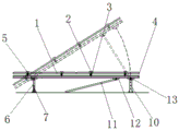
Fig. 1 is a schematic structural diagram of the present invention.
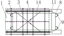
Fig. 2 is a top view of the present invention.
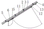
Fig. 3 is a schematic view of the dismounting structure of the present invention.
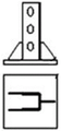
FIG. 4 is a schematic view of a flat steel beam.
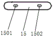
Fig. 5 is a schematic structural view of the prop drawing connecting member.
Fig. 6 is a schematic view of the structure of the lug.
Wherein: the photovoltaic cell module comprises a photovoltaic cell module 1, a pressing block 2, purlins 3, steel beams 4, beam-column connectors 5, beam-column connectors 6, front support posts 7, front support posts 8, a base 8, a towing ring 9, a rear support post 10, rear support posts 11, beam-column connectors 12, horizontal connectors 13, supports 14, support posts 15, bolt holes A1501 and bolt holes B1502.
Detailed Description
The present invention will be further described with reference to the accompanying drawings.
A detachable adjustable photovoltaic support comprises a pressing block 2, a purline 3, supports 14, a steel beam 4, beam column connectors, a front support 6, a rear support 11, a front support 7, a rear support 10, a base 8, a towing hanging ring 9 and a flat connector 13, wherein the towing hanging ring 9 is installed at two ends of the base 8, the front support 7 and the rear support 10 are installed at the top of the base 8, bolt holes are formed in the front support 7 and the rear support 10, the bolt holes in the front support 7 are connected with one end of the front support 6 through bolts, the other end of the front support 6 is connected with a beam column connector A5 through bolts, and the beam column connector A5 is welded at the bottom of the steel beam 4; the bolt hole on the rear support 10 is connected with one end of a rear support column 11 through a bolt, the other end of the rear support column 11 is connected with a beam-column connecting piece B12 through a bolt, and the beam-column connecting piece B12 is welded at the bottom of the steel beam 4; the bottom of the steel beam 4 is provided with a strut furling connecting piece 15, the strut furling connecting piece 15 is provided with a bolt hole A1501 and a bolt hole B1502, the bolt hole A1501 is connected with one end of the front strut 6 far away from the beam-column connecting piece A5 through a bolt, the bolt hole B1502 is connected with one end of the rear strut 11 far away from the beam-column connecting piece B12 through a bolt, and one end of the bottom of the steel beam 4 is welded with a horizontal connecting piece 13; purlins 3 are distributed on the tops of the steel beams 4, the purlins 3 are fixed on the tops of the steel beams 4 through supports 14, the supports 14 are fixed in a crossed mode, and the end portions of the supports 14 are fixed on the steel beams 4 through bolts; and the top of the purline 3 is fixed with a photovoltaic cell assembly 1 through a pressing block 2.
The base 8 is made of steel pipes or reinforced concrete.
The section of the end part of the base 8 is outwards inclined or the end part is upwards bent.
The number of the towing and hanging rings 9 of each detachable unit is not less than 4.
The lower part of the front pillar 6 is provided with 2 bolts.
The lower part of the rear support 11 is provided with 1 bolt.
The rear support 11 and the steel beam 4 form an included angle of 90 degrees.
The end part of the support 14 is fixed on the steel beam 4 by adopting a turn-buckle bolt.
A detachable and adjustable photovoltaic bracket is characterized in that a photovoltaic cell assembly 1 is fixed on a purline 3 through a pressing block 2, and cross supports 14 are arranged in the surface of a steel beam 4; the beam-column connecting piece is respectively used for connecting the steel beam 4 with the front column 6 and the rear column 11; the front strut 6 and the front support 7 are connected by bolts, and the rear strut 11 and the rear support 10 are connected by bolts; the strut furling connecting piece 15 is used for connecting the roots of the front strut 6 and the rear strut 11 when the photovoltaic support is disassembled and assembled, so that the front strut 6 and the rear strut 11 are collinear and parallel to the steel beam 4, the beam-column structure is more compact, the bottom is flat, and the carrying and the storage are convenient; the front support 7 and the rear support 10 are connected to the base 8, and the towing ring 9 is arranged at two ends of the base 8; the lay-flat connector 13 is connected to the steel beam 4.
The support 14 is a turn buckle bolt, and is installed after the purline 3 is installed, when the bolt is tightened, the purline 3 is pressed, and at the moment, the purline 3 is a bending component; the steel beam 4, the purline 3 and the support 14 form a plane structure system, so that enough in-plane rigidity is provided for the photovoltaic cell assembly 1, and the photovoltaic cell assembly 1 is prevented from being stressed due to plane distortion in the carrying process.
The inclination angle of the rear strut 11 is comprehensively determined according to the inclination angle of the steel beam 4, the wind load value and the self weight of the photovoltaic cell assembly 1, and the included angle between the rear strut 11 and the steel beam 4 is 90 degrees; the rear support post 11 is obliquely arranged, so that the stress is more direct when the rear support post is subjected to wind and suction, the shearing stress in the vertical arrangement is changed into approximate axial tension, the horizontal displacement in the plane of the photovoltaic support under the worst combination is effectively reduced, and the photovoltaic cell assembly 1 is better protected. The front support 7 and the rear support 10 are provided with adjusting bolt holes, the lower part of each front strut 6 is provided with two bolts, and the lower part of each rear strut 11 is provided with a bolt which is respectively used as a fixed support and a hinged support of the front strut 6 and the rear strut 11. The front strut 6 is provided with two bolts which can be arranged in any two consecutive bolt holes of the front bracket 7; the rear pillar 11 is provided with a bolt which can be arranged in any bolt hole of the rear bracket 10; the angle of the photovoltaic support can be correspondingly adjusted according to the optimal sunshine angle in different areas, and the height of the photovoltaic support can be correspondingly adjusted according to the high water level in different areas.
The base 8 is made of steel pipes or reinforced concrete materials which meet the requirements after detection, and enough rigidity is ensured to meet the flatness requirement; the tip section of base 8 is camber or tip is bent up, and the tip is bent up, wholly drags reducible resistance when having the relief change in the place, better adapts to complicated place. The dragging and hanging rings 9 are arranged at the end parts of the base 8, the number of the dragging and hanging rings 9 in each detachable unit is not less than 4, and the dragging and hanging rings serve as stress points for dragging and hanging the whole unit and are convenient for fine adjustment of a target position.
The flat connecting piece 13 can be used for alarming in strong wind, after the bolts of the rear support 11 are disassembled, the steel beam 4 is directly connected to the rear support 10, the inclination angle of the battery pack is reduced, the wind load is reduced to a certain degree, and the anti-overturning and sliding and upward pulling stability of the whole structure is facilitated. Meanwhile, the horizontal connecting piece 13 can also be used as a step for dismounting the photovoltaic support, the bolts of the rear support posts 11 are firstly dismounted, the steel beams 4 are horizontally placed by the horizontal connecting piece 13, the rear support posts 11 are not stressed, the bolts of the front support posts 6 are dismounted, and manpower and material resources for dismounting the photovoltaic support are saved.
Claims (8)
1. The utility model provides a dismantled and assembled adjustable photovoltaic support, includes briquetting (2), purlin (3), supports (14), girder steel (4), beam column connecting piece, preceding pillar (6), back pillar (11), preceding support (7), back support (10), base (8), drags hanging ring (9) and keeps flat connecting piece (13), its characterized in that: the steel beam-column connecting piece is characterized in that drag rings (9) are installed at two ends of the base (8), a front support (7) and a rear support (10) are installed at the top of the base (8), bolt holes are formed in the front support (7) and the rear support (10), the bolt holes in the front support (7) are connected with one end of a front column (6) through bolts, the other end of the front column (6) is connected with a beam-column connecting piece A (5) through bolts, and the beam-column connecting piece A (5) is welded at the bottom of a steel beam (4); the bolt hole on the rear support (10) is connected with one end of a rear pillar (11) through a bolt, the other end of the rear pillar (11) is connected with a beam-column connecting piece B (12) through a bolt, and the beam-column connecting piece B (12) is welded at the bottom of the steel beam (4); the bottom of the steel beam (4) is provided with a strut furling connecting piece (15), the strut furling connecting piece (15) is provided with a bolt hole A (1501) and a bolt hole B (1502), the bolt hole A (1501) is connected with one end of a front strut (6) far away from the beam-column connecting piece A (5) through a bolt, the bolt hole B (1502) is connected with one end of a rear strut (11) far away from the beam-column connecting piece B (12) through a bolt, and one end of the bottom of the steel beam (4) is welded with a horizontal connecting piece (13); purlins (3) are distributed on the top of the steel beam (4), the purlins (3) are fixed on the top of the steel beam (4) through supports (14), the supports (14) are fixed in a crossed mode, and the end portions of the supports (14) are fixed on the steel beam (4) through bolts; the photovoltaic cell assembly (1) is fixed at the top of the purline (3) through the pressing block (2).
2. The removable adjustable photovoltaic rack of claim 1, wherein: the base (8) is made of steel pipes or reinforced concrete.
3. A removable adjustable photovoltaic rack according to claim 1 or claim 2, wherein: the section of the end part of the base (8) is outwards inclined or the end part is upwards bent.
4. The removable adjustable photovoltaic rack of claim 1, wherein: the number of the towing and hanging rings (9) of each detachable unit is not less than 4.
5. The removable adjustable photovoltaic rack of claim 1, wherein: the lower part of the front pillar (6) is provided with 2 bolts.
6. The removable adjustable photovoltaic rack of claim 1, wherein: the lower part of the rear pillar (11) is provided with 1 bolt.
7. The removable and adjustable photovoltaic rack of claim 1 or 6, wherein: the included angle between the rear support (11) and the steel beam (4) is 90 degrees.
8. The removable adjustable photovoltaic rack of claim 1, wherein: the end part of the support (14) is fixed on the steel beam (4) by adopting a turn-buckle bolt.
Priority Applications (1)
| Application Number | Priority Date | Filing Date | Title |
|---|---|---|---|
| CN202021485084.XU CN212463124U (en) | 2020-07-24 | 2020-07-24 | Dismantled and assembled adjustable photovoltaic support |
Applications Claiming Priority (1)
| Application Number | Priority Date | Filing Date | Title |
|---|---|---|---|
| CN202021485084.XU CN212463124U (en) | 2020-07-24 | 2020-07-24 | Dismantled and assembled adjustable photovoltaic support |
Publications (1)
| Publication Number | Publication Date |
|---|---|
| CN212463124U true CN212463124U (en) | 2021-02-02 |
Family
ID=74475947
Family Applications (1)
| Application Number | Title | Priority Date | Filing Date |
|---|---|---|---|
| CN202021485084.XU Active CN212463124U (en) | 2020-07-24 | 2020-07-24 | Dismantled and assembled adjustable photovoltaic support |
Country Status (1)
| Country | Link |
|---|---|
| CN (1) | CN212463124U (en) |
-
2020
- 2020-07-24 CN CN202021485084.XU patent/CN212463124U/en active Active
Similar Documents
| Publication | Publication Date | Title |
|---|---|---|
| CN202125105U (en) | Buried single column small photovoltaic bracket | |
| CN201263131Y (en) | Plate type solar battery stent | |
| CN206442336U (en) | A kind of screw pile adjusting post photovoltaic power plant bracket | |
| CN212463124U (en) | Dismantled and assembled adjustable photovoltaic support | |
| CN205295961U (en) | Bridge top pushes away displacement monitoring of construction pier and braced system | |
| CN205921551U (en) | Photovoltaic cell module's installing support | |
| CN111769790A (en) | Dismantled and assembled adjustable photovoltaic support | |
| CN206759374U (en) | A kind of novel foundation stake adjustable photovoltaic support | |
| CN213061799U (en) | Vehicle restriction device for bridge engineering | |
| CN213484787U (en) | Photovoltaic power generation board mounting and supporting structure with suspended steel beam foundation | |
| CN210273901U (en) | Connecting assembly for photovoltaic support and prestressed concrete pipe pile | |
| CN210178392U (en) | Excavation support aligning and tilting prevention device | |
| CN206698170U (en) | A kind of grid-connected photovoltaic system solar energy cell plate mounting bracket | |
| CN209748456U (en) | Fixed single-upright photovoltaic support | |
| CN206402153U (en) | A kind of photovoltaic power plant bracket of adjustable inclination | |
| CN209949014U (en) | Dead weight formula photovoltaic support | |
| CN218301279U (en) | Large-span photovoltaic support with stable cable rod mechanism | |
| CN205857227U (en) | A kind of wind power generation stepped hyollow foundation support | |
| CN220359069U (en) | Adjustable support of single stand | |
| CN205986720U (en) | Install quick single -upright -column photovoltaic support | |
| CN209748464U (en) | Flat ground fixed adjustable photovoltaic support | |
| CN213927640U (en) | Building engineering assembled bearing structure | |
| CN215211954U (en) | Aluminum alloy photovoltaic support system with adjustable inclination | |
| CN217929270U (en) | Photovoltaic support structure for slope and photovoltaic system | |
| CN206673885U (en) | A kind of solar cell module being easily installed |
Legal Events
| Date | Code | Title | Description |
|---|---|---|---|
| GR01 | Patent grant | ||
| GR01 | Patent grant |