CN212458345U - Level measurement device for civil engineering - Google Patents
Level measurement device for civil engineering Download PDFInfo
- Publication number
- CN212458345U CN212458345U CN201821853654.9U CN201821853654U CN212458345U CN 212458345 U CN212458345 U CN 212458345U CN 201821853654 U CN201821853654 U CN 201821853654U CN 212458345 U CN212458345 U CN 212458345U
- Authority
- CN
- China
- Prior art keywords
- fixed
- box body
- supporting rod
- rod
- sleeve
- Prior art date
- Legal status (The legal status is an assumption and is not a legal conclusion. Google has not performed a legal analysis and makes no representation as to the accuracy of the status listed.)
- Expired - Fee Related
Links
Images

Abstract
The utility model discloses a level measuring device used in civil engineering, which comprises a sleeve cover, a sleeve, a box body, a fixed seat, a sliding chute, a first supporting rod, a connecting rod, a rotating shaft, a angle measuring plate, a pointer, a fixed pulley, a through hole, an iron sleeve, a universal wheel, a horizontal base, a second supporting rod, a fixed plate, an adjusting screw, a threaded hole, a limiting hole, a glass plate and a horizontal bubble tube, wherein the fixed plate is fixed at the bottom center position of the box body by welding, the fixed rod is movably connected with one side of the fixed plate by a pin shaft, the threaded hole is arranged at one side of the fixed rod, the adjusting screw is arranged in the threaded hole, the limiting hole is arranged at the connecting part of the adjusting screw and the bottom of the box body, the second supporting rod is fixed at the bottom center position of the fixed rod by welding, the utility model discloses, have the characteristics that the practicality is strong and measurement accuracy is high.
Description
Technical Field
The utility model relates to a civil engineering technical field specifically is a level measurement device that civil engineering used.
Background
A leveling device is a tool used to measure whether the surface of an object is level. In the field of civil engineering, leveling devices are frequently used as a tool for measuring houses, roads, railways, bridges and buildings.
The conventional leveling device has the problems of poor practicability and low measurement accuracy. In the actual measurement process, the measurement efficiency is reduced due to the complex measurement process and measurement operation, and the practicability is reduced due to the inconvenience in measuring the offset angle; meanwhile, the whole measurement precision is reduced due to large measurement error. Therefore, it is necessary to design a leveling device for civil engineering works which is highly practical and highly accurate.
SUMMERY OF THE UTILITY MODEL
An object of the utility model is to provide a level measurement device that civil engineering used to solve the problem that proposes in the above-mentioned background art.
In order to solve the technical problem, the utility model provides a following technical scheme: a horizontal measuring device used in civil engineering comprises a sleeve cover, a sleeve, a box body, a fixed seat, a sliding chute, a first supporting rod, a connecting rod, a rotating shaft, a protracting plate, a pointer, a fixed pulley, a through hole, an iron sleeve, a universal wheel, a horizontal base, a second supporting rod, a fixed plate, an adjusting screw, a threaded hole, a limiting hole, a glass plate and a horizontal bubble tube, wherein the fixed plate is fixed at the center position of the bottom of the box body through welding, the fixed rod is movably connected with one side of the fixed plate through a pin shaft, the threaded hole is formed at one side of the fixed rod, the adjusting screw is installed in the threaded hole, the limiting hole is formed at the joint of the adjusting screw and the bottom of the box body, the second supporting rod is fixed at the center position of the bottom of the fixed rod through welding, the horizontal base is fixed at the bottom, sleeves are correspondingly arranged at two sides of the bottom of the box body, sleeve covers are movably connected at the bottoms of the sleeves through buckles, a universal wheel is arranged inside the sleeve cover, a first supporting rod is fixed at the top of the universal wheel through a screw, an iron sleeve is sleeved outside the first supporting rod, the iron sleeve passes through the through hole, the fixed pulleys are correspondingly arranged on the two sides of the first supporting rod, the tail end of the first supporting rod is movably connected with a connecting rod through a hinge, a pointer is fixed at the center of one end of the connecting rod through welding, a rotating shaft passes through the center of one side of the connecting rod, a fixed seat is evenly arranged between the inner walls of the two sides of the box body, a sliding groove is arranged on one side of the fixed seat, the glass plate is embedded into one side of the box body, and a horizontal bubble tube is installed in the center of one side of the box body.
Further, the fixed pulley and the first supporting rod are fixed through screws, and the fixed pulley moves inside the sliding groove.
Furthermore, the rotating shaft and the connecting rod are fixed through welding, and bearings are arranged at the joints of the two ends of the rotating shaft and the box body.
Furthermore, a pull ring is fixed at the center of the top of the box body through a screw.
Furthermore, the number of the fixing seats is four, and the fixing seats and the box body are fixed through screws.
Furthermore, the inner wall of the top of the sleeve cover and the bottom surface of the horizontal base are positioned on the same plane.
Compared with the prior art, the utility model discloses the beneficial effect who reaches is: the utility model discloses, through being provided with components such as box, first bracing piece, iron sheath, adjusting screw, connecting rod and horizontal bubble tube, be used for carrying out measurement work, make the box be in the horizontality through adjusting screw, and can learn whether the surface of testee is horizontal through the deflection condition of observing the pointer, be convenient for simple and convenient measurement operation process, improve work efficiency, and can record down deflection angle through the quantity scute, and then strengthened the practicality of the device; through being provided with components such as universal wheel, angulation board and pointer, be used for measuring and take notes the surperficial two places position of testee and the contained angle of horizontal direction to through the deflection angle of two pointers of record comparison, be convenient for reduce measuring error, and through the universal wheel with survey the surface contact of object, reduced area of contact, be convenient for promote measurement accuracy.
Drawings
The accompanying drawings are included to provide a further understanding of the invention, and are incorporated in and constitute a part of this specification, illustrate embodiments of the invention, and together with the description serve to explain the invention and not to limit the invention. In the drawings:
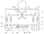
fig. 1 is a schematic view of the overall front sectional structure of the present invention;
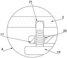
fig. 2 is a schematic structural diagram of the region a in fig. 1 according to the present invention;
fig. 3 is a schematic overall front view structure of the present invention;
in the figure: 1. a sleeve cover; 2. a sleeve; 3. a box body; 4. a fixed seat; 5. a chute; 6. a first support bar; 7. a connecting rod; 8. a rotating shaft; 9. a angle measuring plate; 10. a pointer; 11. a fixed pulley; 12. a through hole; 13. an iron sleeve; 14. a universal wheel; 15. a horizontal base; 16. a second support bar; 17. fixing the rod; 18. a fixing plate; 19. an adjusting screw; 20. a threaded hole; 21. a limiting hole; 22. a glass plate; 23. and a horizontal bubble tube.
Detailed Description
The technical solutions in the embodiments of the present invention will be described clearly and completely with reference to the accompanying drawings in the embodiments of the present invention, and it is obvious that the described embodiments are only some embodiments of the present invention, not all embodiments. Based on the embodiments in the present invention, all other embodiments obtained by a person skilled in the art without creative work belong to the protection scope of the present invention.
Referring to fig. 1-3, the present invention provides a technical solution: a level measuring device used in civil engineering comprises a sleeve cover 1, a sleeve 2, a box body 3, a fixed seat 4, a chute 5, a first supporting rod 6, a connecting rod 7, a rotating shaft 8, a angle measuring plate 9, a pointer 10, a fixed pulley 11, a through hole 12, an iron sleeve 13, a universal wheel 14, a horizontal base 15, a second supporting rod 16, a fixed rod 17, a fixed plate 18, an adjusting screw 19, a threaded hole 20, a limiting hole 21, a glass plate 22 and a horizontal bubble tube 23, wherein the fixed plate 18 is fixed at the center of the bottom of the box body 3 through welding, the fixed rod 17 is movably connected with one side of the fixed plate 18 through a pin shaft, the threaded hole 20 is formed at one side of the fixed rod 17, the adjusting screw 19 is installed inside the threaded hole 20, the limiting hole 21 is formed at the joint of the adjusting screw 19 and the bottom of the box body 3, the second supporting rod 16 is fixed at the center of the bottom of the fixed, a through hole 12 is correspondingly arranged at the center of the inner wall at the bottom of the box body 3, sleeves 2 are correspondingly arranged at two sides of the bottom of the box body 3, the bottom of each sleeve 2 is movably connected with a sleeve cover 1 through a buckle, a universal wheel 14 is arranged inside each sleeve cover 1, a first supporting rod 6 is fixed at the top of each universal wheel 14 through a screw, an iron sleeve 13 is sleeved outside each first supporting rod 6, each iron sleeve 13 penetrates through the corresponding through hole 12, fixed pulleys 11 are correspondingly arranged at two sides of each first supporting rod 6, the tail end of each first supporting rod 6 is movably connected with a connecting rod 7 through a hinge, a pointer 10 is fixed at the center of one end of each connecting rod 7 through welding, a rotating shaft 8 penetrates through the center of one side of each connecting rod 7, fixing seats 4 are uniformly arranged between the inner walls at two sides of the box body 3, a sliding groove 5 is arranged at one side of each fixing seat 4, a protract, a horizontal bubble tube 23 is arranged at the center of one side of the box body 3, a fixed pulley 11 is fixed with the first supporting rod 6 through screws, the fixed pulley 11 moves in the sliding groove 5 to facilitate the up-and-down movement of the first supporting rod 6, the rotating shaft 8 is fixed with the connecting rod 7 through welding, bearings are arranged at the joints of the two ends of the rotating shaft 8 and the box body 3 to facilitate the rotation of the connecting rod 7, a pull ring is fixed at the center of the top of the box body 3 through screws to facilitate the taking and placing of the whole device, the number of the fixed seats 4 is four, and the fixed seats 4 are fixed with the box body 3 through screws to facilitate the improvement of the connection strength of the fixed seats 4, the inner wall of the top of the sleeve cover 1 and the bottom surface of the horizontal base 15 are positioned on the same plane to; when using the device, the sleeve cover 1 is firstly opened through the buckle, the horizontal base 15 is placed on the surface of the measured object, then the box body 3 is in a horizontal state by observing the horizontal bubble tube 23 and adjusting the adjusting screw 19, then, the universal wheels 14 are contacted with the surface of the object to be measured under the action of the self gravity of the first supporting rod 6 and the iron sleeve 13, if the surface of the object to be measured is inclined, the first supporting rod 6 is moved upwards or downwards under the action of the sliding chute 5 and the fixed pulley 11, so that the connecting rod 7 is driven to deflect around the rotating shaft 8, the pointer 10 deflects, if the surface of the measured object is horizontal, the pointer 10 cannot deflect, and finally whether the surface of the measured object is horizontal or not can be known by observing the deflection condition of the pointer 10, so that the measuring operation process is convenient and simple, and the deflection angle can be recorded through the quantity angle plate 9, so that the practicability of the device is enhanced; meanwhile, the device is provided with two universal wheels 14, a first supporting rod 6, a connecting rod 7, pointers 10 and a angle measuring plate 9, included angles between two positions on the surface of a measured object and the horizontal direction can be measured, the deflection angles of the two pointers 10 are compared through recording, measuring errors are convenient to reduce, the universal wheels 14 are in surface contact with the measured object, the contact area is reduced, and the measuring precision is convenient to improve.
It is noted that, herein, relational terms such as first and second, and the like may be used solely to distinguish one entity or action from another entity or action without necessarily requiring or implying any actual such relationship or order between such entities or actions. Also, the terms "comprises," "comprising," or any other variation thereof, are intended to cover a non-exclusive inclusion, such that a process, method, article, or apparatus that comprises a list of elements does not include only those elements but may include other elements not expressly listed or inherent to such process, method, article, or apparatus.
Finally, it should be noted that: although the present invention has been described in detail with reference to the foregoing embodiments, it will be apparent to those skilled in the art that modifications may be made to the embodiments described in the foregoing embodiments, or equivalents may be substituted for elements thereof. Any modification, equivalent replacement, or improvement made within the spirit and principle of the present invention should be included in the protection scope of the present invention.
Claims (6)
1. The utility model provides a level measurement device that civil engineering used, including sleeve lid (1), sleeve (2), box (3), fixing base (4), spout (5), first bracing piece (6), connecting rod (7), pivot (8), angulation board (9), pointer (10), fixed pulley (11), through-hole (12), iron set (13), universal wheel (14), horizontal base (15), second bracing piece (16), dead lever (17), fixed plate (18), adjusting screw (19), screw hole (20), spacing hole (21), glass board (22) and horizontal bubble tube (23), its characterized in that: a fixing plate (18) is fixedly welded at the center of the bottom of the box body (3), a fixing rod (17) is movably connected at one side of the fixing plate (18) through a pin shaft, a threaded hole (20) is formed in one side of the fixing rod (17), an adjusting screw (19) is installed inside the threaded hole (20), a limiting hole (21) is formed in the joint of the adjusting screw (19) and the bottom of the box body (3), a second supporting rod (16) is fixedly welded at the center of the bottom of the fixing rod (17), a horizontal base (15) is fixedly welded at the bottom of the second supporting rod (16), a through hole (12) is correspondingly formed in the center of the inner wall of the bottom of the box body (3), sleeves (2) are correspondingly installed at two sides of the bottom of the box body (3), and sleeve covers (1) are movably connected at the bottoms of the sleeves (2, the sleeve cover is characterized in that a universal wheel (14) is arranged inside the sleeve cover (1), a first supporting rod (6) is fixed at the top of the universal wheel (14) through a screw, an iron sleeve (13) is sleeved outside the first supporting rod (6), the iron sleeve (13) penetrates through a through hole (12), fixed pulleys (11) are correspondingly installed on two sides of the first supporting rod (6), the tail end of the first supporting rod (6) is movably connected with a connecting rod (7) through a hinge, a pointer (10) is fixedly arranged at the center of one end of the connecting rod (7) through welding, a rotating shaft (8) penetrates through the center of one side of the connecting rod (7), fixing seats (4) are uniformly arranged between inner walls of two sides of the box body (3), a sliding groove (5) is formed in one side of each fixing seat (4), a protracting plate (9) is correspondingly installed on the inner wall of one side of the box body (3), and a glass plate (22) is embedded into, a horizontal bubble tube (23) is arranged at the center of one side of the box body (3).
2. A levelling device for civil engineering use according to claim 1, in which: the fixed pulley (11) and the first supporting rod (6) are fixed through screws, and the fixed pulley (11) moves in the sliding groove (5).
3. A levelling device for civil engineering use according to claim 1, in which: the rotating shaft (8) and the connecting rod (7) are fixed through welding, and bearings are arranged at the connecting positions of the two ends of the rotating shaft (8) and the box body (3).
4. A levelling device for civil engineering use according to claim 1, in which: and a pull ring is fixed at the center of the top of the box body (3) through a screw.
5. A levelling device for civil engineering use according to claim 1, in which: the number of the fixed seats (4) is four, and the fixed seats (4) are fixed with the box body (3) through screws.
6. A levelling device for civil engineering use according to claim 1, in which: the inner wall of the top of the sleeve cover (1) and the bottom surface of the horizontal base (15) are positioned on the same plane.
Priority Applications (1)
| Application Number | Priority Date | Filing Date | Title |
|---|---|---|---|
| CN201821853654.9U CN212458345U (en) | 2018-11-12 | 2018-11-12 | Level measurement device for civil engineering |
Applications Claiming Priority (1)
| Application Number | Priority Date | Filing Date | Title |
|---|---|---|---|
| CN201821853654.9U CN212458345U (en) | 2018-11-12 | 2018-11-12 | Level measurement device for civil engineering |
Publications (1)
| Publication Number | Publication Date |
|---|---|
| CN212458345U true CN212458345U (en) | 2021-02-02 |
Family
ID=74479784
Family Applications (1)
| Application Number | Title | Priority Date | Filing Date |
|---|---|---|---|
| CN201821853654.9U Expired - Fee Related CN212458345U (en) | 2018-11-12 | 2018-11-12 | Level measurement device for civil engineering |
Country Status (1)
| Country | Link |
|---|---|
| CN (1) | CN212458345U (en) |
Cited By (2)
| Publication number | Priority date | Publication date | Assignee | Title |
|---|---|---|---|---|
| CN117606445A (en) * | 2024-01-22 | 2024-02-27 | 湖北水总水利水电建设股份有限公司 | Portable slope measuring device for hydraulic engineering construction |
| CN117606445B (en) * | 2024-01-22 | 2024-04-23 | 湖北水总水利水电建设股份有限公司 | Portable slope measuring device for hydraulic engineering construction |
-
2018
- 2018-11-12 CN CN201821853654.9U patent/CN212458345U/en not_active Expired - Fee Related
Cited By (2)
| Publication number | Priority date | Publication date | Assignee | Title |
|---|---|---|---|---|
| CN117606445A (en) * | 2024-01-22 | 2024-02-27 | 湖北水总水利水电建设股份有限公司 | Portable slope measuring device for hydraulic engineering construction |
| CN117606445B (en) * | 2024-01-22 | 2024-04-23 | 湖北水总水利水电建设股份有限公司 | Portable slope measuring device for hydraulic engineering construction |
Similar Documents
| Publication | Publication Date | Title |
|---|---|---|
| CN110055838B (en) | Working track installation mechanism of transverse working trolley of trailing suction hopper dredger | |
| CN209013891U (en) | A kind of stake holes hole diameter detection apparatus | |
| CN212458345U (en) | Level measurement device for civil engineering | |
| CN206740055U (en) | A kind of steel plate welding procedure detection means | |
| CN210952737U (en) | Flatness detection device for building construction template | |
| CN217877696U (en) | Practical building measuring instrument | |
| CN109458989A (en) | A kind of device and its detection method for building verticality quality testing | |
| CN211346782U (en) | Level detecting system for building | |
| CN211651594U (en) | Special gradient measuring device of building engineering | |
| CN211235473U (en) | Device for measuring underwater dynamic and static friction coefficients between plastic plate and steel plate | |
| CN211954229U (en) | Clamping device for instrument calibration | |
| CN210570549U (en) | Foundation pit position measuring device | |
| CN110044230B (en) | Novel spare part assembly error detects device | |
| CN208059741U (en) | A kind of construction-engineering project management detection ruler | |
| CN207688885U (en) | Quickly measure the tool of verticality of steel column | |
| CN215572576U (en) | Bridge floor distance measuring device for bridge engineering | |
| CN213867740U (en) | Municipal facility monitoring system | |
| CN215114331U (en) | Automatic height inspection device for mechanical parts | |
| CN214893235U (en) | House building detection and identification field test device | |
| CN215572638U (en) | Building engineering is with straightness detection device that hangs down | |
| CN214893038U (en) | Engineering construction measuring device | |
| CN211651407U (en) | Multifunctional caliper | |
| CN215052821U (en) | Light-duty sounding instrument for detecting bearing capacity of foundation | |
| CN106500665A (en) | Patrolling transmission line tiltometer | |
| CN220463882U (en) | Geophysical prospecting ground marking device based on ranging wheel is used |
Legal Events
| Date | Code | Title | Description |
|---|---|---|---|
| GR01 | Patent grant | ||
| GR01 | Patent grant | ||
| CF01 | Termination of patent right due to non-payment of annual fee |
Granted publication date: 20210202 Termination date: 20211112 |
|
| CF01 | Termination of patent right due to non-payment of annual fee |