CN212444629U - Stamping workpiece grinding device - Google Patents
Stamping workpiece grinding device Download PDFInfo
- Publication number
- CN212444629U CN212444629U CN202020470516.3U CN202020470516U CN212444629U CN 212444629 U CN212444629 U CN 212444629U CN 202020470516 U CN202020470516 U CN 202020470516U CN 212444629 U CN212444629 U CN 212444629U
- Authority
- CN
- China
- Prior art keywords
- rods
- base
- polishing
- rotating
- fixedly mounted
- Prior art date
- Legal status (The legal status is an assumption and is not a legal conclusion. Google has not performed a legal analysis and makes no representation as to the accuracy of the status listed.)
- Expired - Fee Related
Links
Images


Abstract
The utility model belongs to the stamping workpiece field of polishing, especially a stamping workpiece grinding device, including placing subaerial base, the top fixed mounting of base has branch and montant, and the top fixed mounting of branch has the board of placing, the equal fixed mounting in both sides of placing the board has the baffle, has seted up the perforation on one of them baffle, and fenestrate one side is equipped with the carousel, the top fixed mounting of base has the rotation motor. The utility model discloses simple structure, convenient to use can press from both sides tightly the polishing to the stamping workpiece, and the process is more automatic, labour saving and time saving.
Description
Technical Field
The utility model relates to a stamping workpiece field of polishing especially relates to a stamping workpiece grinding device.
Background
At present, the metal manufacturing industry is rapidly developed, the metal manufacturing stamping part has more and more complex structure for metal processing, the requirement on the size precision of the part in the trimming and shaping process is higher and higher, and the method is also one of the key factors for ensuring the size precision of the final metal pressing part.
The patent with application number 201911185845.1 discloses a metal stamping workpiece grinding device, which comprises a housin, be equipped with the process chamber in the casing, the process intracavity is equipped with pressing mechanism, be equipped with grinding mechanism in the process chamber upper end wall, the process chamber downside is equipped with drive mechanism, the process chamber rear side is equipped with actuating mechanism.
However, the lack of a clamping device for the stamping part in the device can cause the stamping part to loosen and generate errors in the grinding process.
SUMMERY OF THE UTILITY MODEL
The utility model aims at solving the defects existing in the prior art and providing a polishing device for stamping parts.
In order to achieve the above purpose, the utility model adopts the following technical scheme:
the utility model provides a stamping workpiece grinding device, is including placing subaerial base, the top fixed mounting of base has branch and montant, and the top fixed mounting of branch has the board of placing, the equal fixed mounting in both sides of placing the board has the baffle, has seted up the perforation on one of them baffle, and fenestrate one side is equipped with the carousel, the top fixed mounting of base has the rotation motor, and the carousel is fixed to be cup jointed on the output shaft that rotates the motor, the montant is close to one side fixed mounting who rotates the motor has the horizontal pole, and the bottom fixed mounting of horizontal pole has hydraulic cylinder, and fixed mounting has the polisher on hydraulic cylinder's the output shaft, and the top fixed mounting of base has the platform of polishing, and the platform of polishing is located the polisher under, the platform.
Preferably, four rotating rods are fixedly arranged on the periphery of the rotating disc at equal intervals, and the rotating rods are movably arranged in the through holes.
Preferably, the top fixed mounting of base has two dead levers, the platform of polishing is located between two dead levers, the commentaries on classics hole has all been seted up on one side of two dead levers, all rotate in the rotation and install the lead screw guide pin bushing, equal screw has cup jointed the lead screw on two lead screw guide bushings, the equal fixed mounting of one end that two lead screws are close to each other has the L template, it has the gear all to cup joint on two lead screw guide bushings, the dead lever is located between gear and the L template, the equal fixed mounting in hydraulic cylinder's the output shaft both sides has the connecting rod, the equal fixed mounting in bottom of two connecting rods has the rack, two racks mesh.
Preferably, the top of the base is fixedly provided with two slide rails, the two slide rails are provided with slide blocks in a sliding manner, and the two slide blocks are fixedly connected with the bottoms of the two screw rods respectively.
Preferably, the top fixed mounting of base has two fixed branch, rotates the motor and is located between two fixed branch, all sets up threaded hole on one side of two fixed branch, and the threaded rod is installed to equal screw thread on two threaded holes, and outside the both ends of two threaded rods all extended to fixed branch, and the equal fixed mounting of one end that two threaded rods are close to each other has semi-circular speed reduction piece, semi-circular speed reduction piece and the output shaft looks adaptation of rotating the motor, and the equal fixed mounting of one end that two threaded rods kept away from each other has manual bull stick.
The utility model discloses in, a stamping workpiece grinding device, through the rotation that starts rotation motor drive carousel, the carousel drives the rotation of bull stick, the bull stick drives and places stamping workpiece on the board to the bench of polishing, then start hydraulic cylinder and drive the rack and move down, the rack drives the rotation of gear, the gear drives the rotation of lead screw guide pin bushing, the rotation of two lead screw guide pin bushings drives two lead screw moves in opposite directions, then two L templates have carried out the clamp to the stamping workpiece on the bench of polishing tightly, the polisher has polished the stamping workpiece.
However, because the polishing time of different types of stamping parts is different, the time required for reaching the polishing platform is different, and the two threaded rods are driven to move in opposite directions by rotating the manual rotating rod, so that the two semicircular speed reducing blocks are driven to be in contact with the output shaft of the rotating motor, the rotating speed of the rotating motor is reduced, and the time for driving the stamping parts to the polishing platform is increased. The utility model discloses simple structure, convenient to use can press from both sides tightly the polishing to the stamping workpiece, and the process is more automatic, labour saving and time saving.
Drawings
Fig. 1 is a schematic structural view of a polishing device for stamping parts according to the present invention;
fig. 2 is a side view of a polishing device for stamping parts according to the present invention with respect to a base;
fig. 3 is the utility model provides a stamping workpiece grinding device's a part schematic structure.
In the figure: the automatic grinding machine comprises a base 1, a grinding table 2, an inclined sliding plate 3, a rotating motor 4, a baffle 5, a rotating rod 6, a rotating disk 7, a perforation 8, a hydraulic oil cylinder 9, a connecting rod 10, a grinding machine 11, a screw rod 12, a screw rod guide sleeve 13, a gear 14, a rack 15, a manual rotating rod 16, a threaded rod 17, a threaded hole 18, a semicircular speed reducing block 19 and a template 20L.
Detailed Description
In the technical scheme:
6. 7, 8, 13, 14 and 12 are the novel structure with substantial innovation.
4. 15 is the realization the utility model discloses technical scheme is essential connectivity component.
The technical solutions in the embodiments of the present invention will be described clearly and completely with reference to the accompanying drawings in the embodiments of the present invention, and it is obvious that the described embodiments are only some embodiments of the present invention, not all embodiments.
Example one
Referring to fig. 1-3, a stamping workpiece grinding device, including placing base 1 subaerial, the top fixed mounting of base 1 has branch and montant, the top fixed mounting of branch has the board of placing, the equal fixed mounting in both sides of placing the board has baffle 5, perforation 8 has been seted up on one of them baffle 5, one side of perforation 8 is equipped with carousel 7, the top fixed mounting of base 1 has rotation motor 4, carousel 7 is fixed to be cup jointed on the output shaft of rotating motor 4, one side fixed mounting that the montant is close to the rotation motor has the horizontal pole, the bottom fixed mounting of horizontal pole has hydraulic cylinder 9, fixed mounting has polisher 11 on hydraulic cylinder 9's the output shaft, the top fixed mounting of base 1 has polishing platform 2, polishing platform 2 is located polisher 11 under, polishing platform 2 and place between the board fixed mounting have same slide 3 to one side.
Example two
Referring to fig. 1-3, a stamping workpiece grinding device, four rotating rods 6 are fixedly installed around a rotary table 7 at equal intervals, the rotating rods 6 are movably installed in through holes 8, and stamping workpieces on a placing plate are driven to a grinding table 2 through rotation of the rotating rods 6.
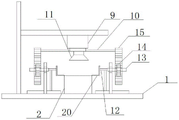
In the utility model, two fixed rods are fixedly installed on the top of a base 1, a polishing platform 2 is positioned between the two fixed rods, a rotating hole is formed on one side of each of the two fixed rods, a screw rod guide sleeve 13 is rotatably installed in the rotating hole, screw rods 12 are screwed on the two screw rod guide sleeves 13, an L-shaped plate 20 is fixedly installed on one end of each of the two screw rods 12 close to each other, gears 14 are fixedly sleeved on the two screw rod guide sleeves 13, the fixed rods are positioned between the gears 14 and the L-shaped plate 20, connecting rods 10 are fixedly installed on both sides of an output shaft of a hydraulic oil cylinder 9, racks 15 are fixedly installed on the bottoms of the two connecting rods 10, the two racks 15 are respectively meshed with the two gears 14, the racks 15 are driven to move downwards by starting the hydraulic oil cylinder 9, the racks 15 drive the gears 14 to rotate, the gears 14 drive the screw rod guide sleeves 13, then, the two L-shaped plates 20 clamp the stamping part on the grinding table 2, and the grinding machine 11 grinds the stamping part.
The utility model discloses in, base 1's top fixed mounting has two slide rails, and equal slidable mounting has the slider on two slide rails, two sliders respectively with two lead screw 12's bottom fixed connection, the slide rail slider makes things convenient for lead screw 12's removal and has played fixed effect to lead screw 12.
The utility model discloses in, base 1's top fixed mounting has two fixed branch, it is located between two fixed branch to rotate motor 4, threaded hole 18 has all been seted up on one side of two fixed branch, threaded rod 17 is installed to equal screw thread on two threaded hole 18, the both ends of two threaded rod 17 all extend to outside the fixed branch, and the equal fixed mounting of one end that two threaded rod 17 are close to each other has semi-circular deceleration piece 19, semi-circular deceleration piece 19 and the output shaft looks adaptation of rotating motor 4, the equal fixed mounting of one end that two threaded rod 17 kept away from each other has manual bull stick 16, through rotating manual bull stick 16, drive two threaded rod 17 and remove in opposite directions, it contacts with the output shaft that rotates motor 4 to drive two semi-circular deceleration pieces 19, then, the rotational speed that rotates motor 4 can reduce, the stamping workpiece is driven to the time that the platform 2 was.
The utility model discloses in, rotate the rotation that motor 4 drove carousel 7 through the start-up, carousel 7 drives the rotation of bull stick 6, bull stick 6 drives and places the stamping workpiece on the board to the platform 2 of polishing, then start hydraulic cylinder 9 and drive rack 15 and move down, rack 15 drives the rotation of gear 14, gear 14 drives the rotation of lead screw guide pin bushing 13, the rotation of two lead screw guide pin bushings 13 drives two lead screw 12 and removes in opposite directions, then two L templates 20 press from both sides tightly the stamping workpiece on the platform 2 of polishing, polisher 11 has polished the stamping workpiece.
However, since the polishing time of different types of stamping parts is different, the time required for the stamping parts to reach the polishing table 2 is different, and the manual rotating rod 16 is rotated to drive the two threaded rods 17 to move oppositely and drive the two semicircular speed reducing blocks 19 to contact with the output shaft of the rotating motor 4, so that the rotating speed of the rotating motor 4 is reduced, and the time for driving the stamping parts to the polishing table 2 is increased. The utility model discloses simple structure, convenient to use can press from both sides tightly the polishing to the stamping workpiece, and the process is more automatic, labour saving and time saving.
The above, only be the concrete implementation of the preferred embodiment of the present invention, but the protection scope of the present invention is not limited thereto, and any person skilled in the art is in the technical scope of the present invention, according to the technical solution of the present invention and the utility model, the concept of which is equivalent to replace or change, should be covered within the protection scope of the present invention.
Claims (5)
1. A polishing device for stamping parts comprises a base (1) placed on the ground, and is characterized in that a supporting rod and a vertical rod are fixedly mounted at the top of the base (1), a placing plate is fixedly mounted at the top of the supporting rod, baffles (5) are fixedly mounted on two sides of the placing plate respectively, a perforation (8) is formed in one baffle (5), a turntable (7) is arranged on one side of the perforation (8), a rotating motor (4) is fixedly mounted at the top of the base (1), the turntable (7) is fixedly sleeved on an output shaft of the rotating motor (4), a cross rod is fixedly mounted on one side of the vertical rod close to the rotating motor, a hydraulic oil cylinder (9) is fixedly mounted at the bottom of the cross rod, a polishing machine (11) is fixedly mounted on the output shaft of the hydraulic oil cylinder (9), a polishing platform (2) is fixedly mounted at the top of the base (1), and the polishing platform, the same inclined sliding plate (3) is fixedly arranged between the grinding table (2) and the placing plate.
2. A grinding device for stamping parts according to claim 1, characterized in that four rotating rods (6) are fixedly arranged around the rotating disc (7) at equal intervals, and the rotating rods (6) are movably arranged in the through holes (8).
3. The polishing device for stamping parts according to claim 1, wherein two fixing rods are fixedly installed at the top of the base (1), the polishing table (2) is located between the two fixing rods, a rotating hole is formed in each of one sides of the two fixing rods, a screw guide sleeve (13) is rotatably installed in each of the two fixing rods, a screw (12) is respectively and threadedly sleeved on each of the two screw guide sleeves (13), an L-shaped plate (20) is respectively and fixedly installed at one end of each of the two screws (12) close to each other, a gear (14) is respectively and fixedly sleeved on each of the two screw guide sleeves (13), the fixing rods are located between the gear (14) and the L-shaped plate (20), connecting rods (10) are respectively and fixedly installed at two sides of an output shaft of the hydraulic cylinder (9), racks (15) are respectively and fixedly installed at the bottoms of the two connecting rods (10), and the.
4. A grinding device for stamping parts according to claim 1, characterized in that two sliding rails are fixedly mounted on the top of the base (1), and a sliding block is slidably mounted on each sliding rail and is respectively fixedly connected with the bottoms of the two screw rods (12).
5. A stamping part grinding device according to claim 1, characterized in that, the top of base (1) is fixedly installed with two fixed supporting rods, rotating motor (4) is located between the two fixed supporting rods, threaded holes (18) are respectively opened on one side of the two fixed supporting rods, threaded rods (17) are respectively installed on the two threaded holes (18) in a threaded manner, both ends of the two threaded rods (17) extend out of the fixed supporting rods, a semicircular speed reducing block (19) is respectively and fixedly installed at one end of the two threaded rods (17) close to each other, the semicircular speed reducing block (19) is adapted to the output shaft of the rotating motor (4), and a manual rotating rod (16) is respectively and fixedly installed at one end of the two threaded rods (17) far away from each other.
Priority Applications (1)
| Application Number | Priority Date | Filing Date | Title |
|---|---|---|---|
| CN202020470516.3U CN212444629U (en) | 2020-04-03 | 2020-04-03 | Stamping workpiece grinding device |
Applications Claiming Priority (1)
| Application Number | Priority Date | Filing Date | Title |
|---|---|---|---|
| CN202020470516.3U CN212444629U (en) | 2020-04-03 | 2020-04-03 | Stamping workpiece grinding device |
Publications (1)
| Publication Number | Publication Date |
|---|---|
| CN212444629U true CN212444629U (en) | 2021-02-02 |
Family
ID=74471696
Family Applications (1)
| Application Number | Title | Priority Date | Filing Date |
|---|---|---|---|
| CN202020470516.3U Expired - Fee Related CN212444629U (en) | 2020-04-03 | 2020-04-03 | Stamping workpiece grinding device |
Country Status (1)
| Country | Link |
|---|---|
| CN (1) | CN212444629U (en) |
-
2020
- 2020-04-03 CN CN202020470516.3U patent/CN212444629U/en not_active Expired - Fee Related
Similar Documents
| Publication | Publication Date | Title |
|---|---|---|
| CN211415498U (en) | Automatic clamping and positioning device for wood board processing | |
| CN116393772A (en) | Multifunctional gear forging tool | |
| CN214445458U (en) | Surface polishing equipment for vertical machining center | |
| CN212444629U (en) | Stamping workpiece grinding device | |
| CN109014153B (en) | Multifunctional casting head automatic cutting equipment convenient to adjust and working method thereof | |
| CN216000260U (en) | Sensor adds clamping apparatus | |
| CN216327187U (en) | Deburring equipment for vehicle door hinge die casting | |
| CN116252213A (en) | Grinding device and mechanical part machining equipment | |
| CN112847681B (en) | Round block cutting equipment for machining round chopping board | |
| CN213795651U (en) | Clamping device for bakelite plate processing | |
| CN218533806U (en) | Tetrafluoro pipeline grinding device | |
| CN112916966A (en) | Rotary workbench for gear blank machining and use method thereof | |
| CN220660274U (en) | Surface polishing device for floor processing | |
| CN220362279U (en) | Aluminum profile plate cutting machine | |
| CN213646956U (en) | Trimming device for metal stamping parts | |
| CN212123436U (en) | Fiberboard cutting device | |
| CN219725690U (en) | Grinding tool for mechanical production | |
| CN220296029U (en) | Blank foundry goods side cut mechanism | |
| CN211540697U (en) | Automatic change ceramic polishing equipment | |
| CN218340721U (en) | Plate slotting bending machine | |
| CN218903679U (en) | Punching equipment for processing die steel plate | |
| CN214583932U (en) | Polishing machine center tooth base vibration test fixture | |
| CN219542382U (en) | Clamping device for machining of die milling machine | |
| CN217071659U (en) | Mould processingequipment convenient to switch station | |
| CN217530292U (en) | Casting work piece burring device |
Legal Events
| Date | Code | Title | Description |
|---|---|---|---|
| GR01 | Patent grant | ||
| GR01 | Patent grant | ||
| CF01 | Termination of patent right due to non-payment of annual fee |
Granted publication date: 20210202 |
|
| CF01 | Termination of patent right due to non-payment of annual fee |