Air purifying device
Technical Field
The utility model relates to an air purification technical field especially relates to an air purification device.
Background
A clean room, also called a clean room or clean room, is a basis for pollution control, and controls the concentration of airborne particles so as to achieve a proper level of particle cleanliness, and is a clean room for removing contaminants such as particles, harmful air, bacteria, etc. from air within a certain spatial range.
Through the retrieval, chinese patent authorizes the patent that is CN207763121U, discloses a movable air purifier, including the air purifier install bin, there is the case lid in the top one side edge of air purifier install bin through the hinge mounting, and the push-pull ring is installed at the top of case lid, and the internally mounted of air purifier install bin has the air purifier main part, and the universal wheel is all installed to four apex angle departments of the bottom of air purifier install bin, and one side of air purifier install bin inlays to establish and installs dust collection device. The utility model is provided with the universal wheels at the bottom of the air purifier mounting box, which is convenient for the air purifier main body to move; the dust particles of the air are filtered through the activated carbon filter screen and the electrostatic dust collection plate, the bacteria microorganisms in the air can be treated through the ultraviolet germicidal lamp, the dust collection drawer capable of filtering the electrostatic dust collection plate can collect the dust filtered by the electrostatic dust collection plate by improving the purification effect and the purification efficiency, the pull ring can extract the dust collection drawer out, and the purification effect is improved. One of the movable air purifiers in the above patent has the following disadvantages: when the conventional device purifies air, the air purification effect may be influenced because the air flow speed is high.
SUMMERY OF THE UTILITY MODEL
The utility model aims at solving the defects existing in the prior art and providing an air purifying device.
In order to achieve the above purpose, the utility model adopts the following technical scheme:
the utility model provides an air purification device, includes the purifying box, the air inlet has been seted up to the position that one side outer wall of purifying box is close to the top, and the inner wall fixedly connected with fan of air inlet, the inner wall fixedly connected with filter screen of purifying box, the inner wall fixedly connected with fixed plate of purifying box, and the equal fixedly connected with baffle of bottom outer wall of fixed plate and the bottom inner wall of purifying box, a plurality of equidistance water conservancy diversion holes that distribute are seted up to one side outer wall of baffle, and the shape in water conservancy diversion hole is the wave, the opening has been seted up to one side outer wall of baffle, and the inner wall edge of opening has the trachea through flange joint, the gas vent has been seted up to one side of purifying box top outer.
As a further aspect of the present invention: one side fixedly connected with protection casing of purifying box top outer wall, and a plurality of through-holes have been seted up to the outer wall of protection casing.
As a further aspect of the present invention: the outer wall of the bottom of the fixing plate is provided with a plurality of filtering holes which are distributed at equal intervals.
As a further aspect of the present invention: threaded holes are formed in the outer wall of one side of the purifying box, a storage box is connected to the inner wall of each threaded hole in a threaded mode, and active carbon is arranged inside the storage box.
As a further aspect of the present invention: the inner wall threaded connection of receiver has the screw cap, and the outer wall of screw cap is carved with anti-skidding line.
As a further aspect of the present invention: ball grooves are formed in four corners of the outer wall of the bottom of the purifying box, and balls are connected to the inner walls of the ball grooves in a rolling mode.
As a further aspect of the present invention: one side outer wall fixedly connected with control panel of purifying box, and one side outer wall of control panel installs the regulator, is electric connection between regulator and the fan.
The utility model has the advantages that:
1. the guide plate and the guide holes can slow down the flowing speed of air so as to be convenient for purifying the air, and the phenomenon that the device cannot effectively purify the air due to the high flowing speed of the air so as to influence the working efficiency of the device is prevented;
2. the storage box, the threaded cover and the activated carbon are arranged, so that moisture in the air can be absorbed, the air can be further purified, and meanwhile, peculiar smell gas in the air can be treated through the activated carbon;
3. through the control panel and the regulator that set up, can adjust the purification efficiency of device as required, improved the energy-conservation nature that the device used.
Drawings
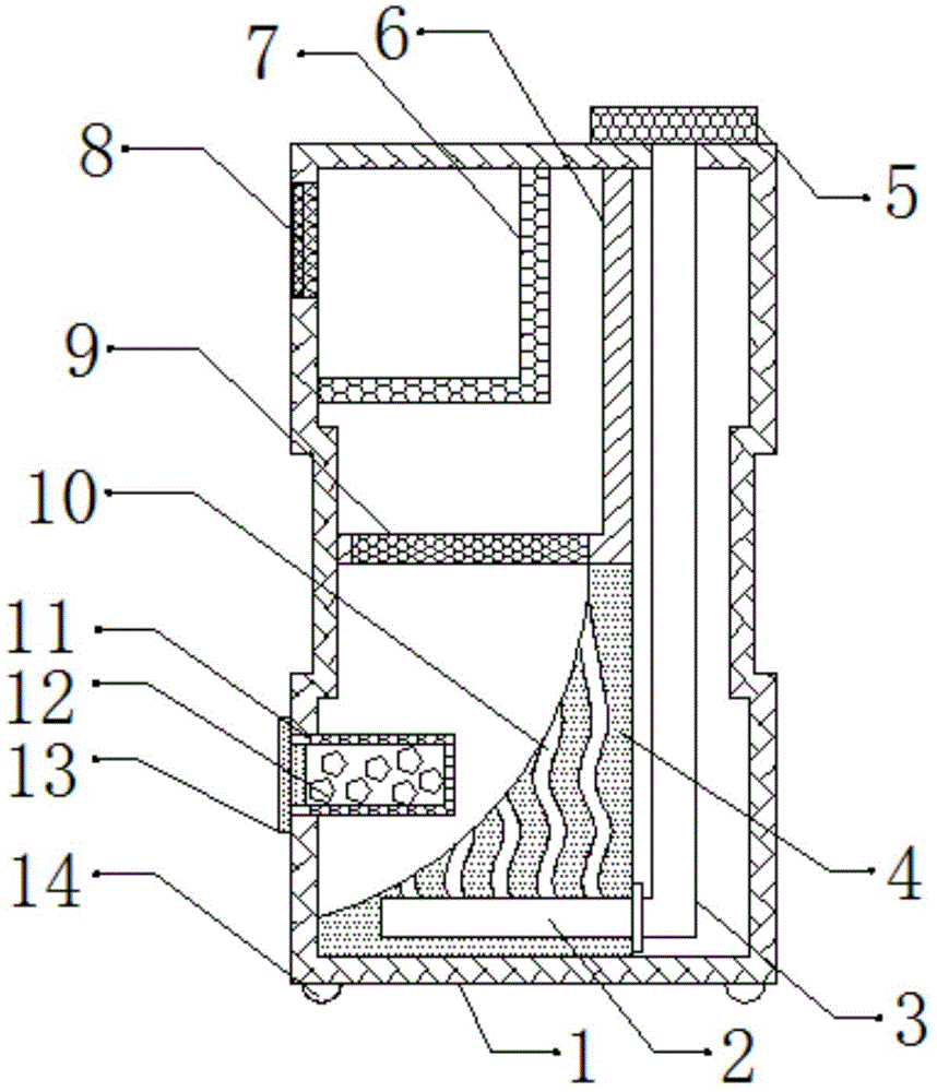
Fig. 1 is a schematic cross-sectional structural view of an air cleaning apparatus according to embodiment 1;
fig. 2 is a schematic view of the overall structure of an air cleaning apparatus according to embodiment 1;
fig. 3 is a schematic cross-sectional structural diagram of an air purification apparatus provided in embodiment 2.
In the figure: 1 purifying box, 2 openings, 3 trachea, 4 baffle, 5 shields, 6 fixed plates, 7 filter screens, 8 fans, 9 filtration holes, 10 water conservancy diversion holes, 11 receivers, 12 active carbon, 13 screw caps, 14 balls, 15 regulators, 16 control panel.
Detailed Description
Reference will now be made in detail to embodiments of the present patent, examples of which are illustrated in the accompanying drawings, wherein like or similar reference numerals refer to the same or similar elements or elements having the same or similar function throughout. The embodiments described below with reference to the drawings are exemplary only for the purpose of explaining the present patent and are not to be construed as limiting the present patent.
In the description of this patent, it is to be understood that the terms "center," "upper," "lower," "front," "rear," "left," "right," "vertical," "horizontal," "top," "bottom," "inner," "outer," and the like are used in the orientations and positional relationships indicated in the drawings for the convenience of describing the patent and for the simplicity of description, and are not intended to indicate or imply that the referenced devices or elements must have a particular orientation, be constructed and operated in a particular orientation, and are not to be considered limiting of the patent.
In the description of this patent, it is noted that unless otherwise specifically stated or limited, the terms "mounted," "connected," and "disposed" are to be construed broadly and can include, for example, fixedly connected, disposed, detachably connected, disposed, or integrally connected and disposed. The specific meaning of the above terms in this patent may be understood by those of ordinary skill in the art as appropriate.
Example 1
Referring to fig. 1-2, an air purification device, including purifying box 1, the air inlet has been seted up to the position that one side outer wall of purifying box 1 is close to the top, and the inner wall of air inlet has fan 8 through bolted connection, the inner wall of purifying box 1 has filter screen 7 through bolted connection, the inner wall of purifying box 1 has fixed plate 6 through bolted connection, and the bottom outer wall of fixed plate 6 and the bottom inner wall of purifying box 1 all have baffle 4 through bolted connection, a plurality of equidistance distribution's water conservancy diversion hole 10 has been seted up to one side outer wall of baffle 4, and the shape of water conservancy diversion hole 10 is the wave, opening 2 has been seted up to one side outer wall of baffle 4, and there is trachea 3 inner wall edge of opening 2 through flange joint, the gas vent has been seted up to one side of purifying box 1.
Wherein, there is protection casing 5 one side of 1 top outer wall of purifying box through bolted connection, and protection casing 5's outer wall has seted up a plurality of through-holes, a plurality of equidistance distribution's filtration pore 9 is seted up to the bottom outer wall of fixed plate 6, one side outer wall of purifying box 1 sets up threaded hole, and the inner wall threaded connection of screw hole has receiver 11, receiver 11's inside is provided with active carbon 12, receiver 11's inner wall threaded connection has screw cap 13, and screw cap 13's outer wall is carved with anti-skidding line, the ball groove has all been seted up in the four corners of 1 bottom outer wall of purifying box, and the inner wall roll connection in ball groove has ball.
The working principle is as follows: during the use, absorb the inside to purifying box 1 with the air through fan 8, carry out preliminary purification treatment to the air through filter screen 7, the air after preliminary purification can further carry out purification treatment through filtration hole 9, can absorb the moisture in the air through active carbon 12, so that further carry out purification treatment to the air, and simultaneously, can handle the peculiar smell gas in the air through active carbon 12, can slow down the flow velocity of air through water conservancy diversion hole 10, so that carry out purification treatment to the air, prevent because the flow velocity of air leads to the device can not purify the air effectively very fast, thereby cause the influence to the work efficiency of device.
Example 2
Referring to fig. 3, in this embodiment, compared with embodiment 1, the outer wall of one side of the purifying box 1 is connected to the control panel 16 through the bolt, and the outer wall of one side of the control panel 16 is installed with the regulator 15, and the regulator 15 is electrically connected to the fan 8.
The working principle is as follows: during the use, absorb the inside to purifying box 1 through fan 8 with the air, carry out preliminary purification treatment to the air through filter screen 7, the air after preliminary purification can further carry out purification treatment through filtration pore 9, can absorb the moisture in the air through active carbon 12, so that further carry out purification treatment to the air, and simultaneously, can handle the peculiar smell gas in the air through active carbon 12, can slow down the flow velocity of air through water conservancy diversion hole 10, so that carry out purification treatment to the air, prevent to lead to the device to purify the air effectively because the flow velocity of air is very fast, thereby cause the influence to the work efficiency of device, can adjust the purification efficiency of device as required through control panel 16 and regulator 15, improve the energy-conservation nature that the device used.
The above, only be the concrete implementation of the preferred embodiment of the present invention, but the protection scope of the present invention is not limited thereto, and any person skilled in the art is in the technical scope of the present invention, according to the technical solution of the present invention and the utility model, the concept of which is equivalent to replace or change, should be covered within the protection scope of the present invention.