CN212438808U - One-way locking pressurization knot-free loop steel plate fixing structure - Google Patents
One-way locking pressurization knot-free loop steel plate fixing structure Download PDFInfo
- Publication number
- CN212438808U CN212438808U CN202022102021.8U CN202022102021U CN212438808U CN 212438808 U CN212438808 U CN 212438808U CN 202022102021 U CN202022102021 U CN 202022102021U CN 212438808 U CN212438808 U CN 212438808U
- Authority
- CN
- China
- Prior art keywords
- hole
- latch
- loop
- steel plate
- main body
- Prior art date
- Legal status (The legal status is an assumption and is not a legal conclusion. Google has not performed a legal analysis and makes no representation as to the accuracy of the status listed.)
- Active
Links
Images


Landscapes
- Surgical Instruments (AREA)
Abstract
The utility model provides a knot tong "pan" steel sheet fixed knot structure is exempted from to one-way locking pressurization, including fracture dislocation offside tong "pan" steel sheet, operation incision side tong "pan" steel sheet, tong "pan line and tail cap, the main part of tong" pan "line passes the third through-hole in the operation incision side tong" pan "steel sheet to the offside, again to offside in proper order in succession pass fracture dislocation offside tong" pan "steel sheet in first through-hole and second through-hole, passes the fourth through-hole in the operation incision side tong" pan "steel sheet to operation incision side again, passes the fifth through-hole in the tail cap at last. The utility model discloses a fifth latch respectively in proper order with the third latch, first latch, second latch and fourth latch interlock all constitute one-way locking structure, through quartic pressurization effect that advances gradually, avoid the part of the in-process pressurization effect of knoing to lose, fixed stability and firm nature have not only been increased, and the tail end of tail cap interlock locking fixed loop line main part is used to the tail end of loop line main part, need not knot, the local knot foreign matter reaction and the uncomfortable sense of having reduced patient's postoperative because of the number of knoing excessively causes.
Description
Technical Field
The utility model relates to a human articles for daily use especially relates to medical instrument, is specifically an one-way locking pressurization exempts from to tie a knot steel sheet fixed knot structure.
Background
The loop steel plate is most commonly used for treating traumatic orthopedic fracture dislocation and is most commonly used for treating inferior tibiofibular dislocation and coracoid clavicular ligament injury. At present, the skeleton to be restored is clamped by two Endo button steel plates (button steel plates) clinically, the two Endo button steel plates are connected by a loop, a loop line penetrates through the skeleton to be restored, one steel plate is placed on the opposite side of fracture dislocation, the other steel plate is placed on the side of an operation incision of the fracture dislocation, and the two steel plates are combined through the loop line, pressurized and knotted to complete fixation. In the prior art, a loop steel plate is fixed by pressing the tail end of a loop wire, in order to maintain the stability of the loop steel plate, the tail end of the loop wire is frequently knotted repeatedly for at least 5 times, and the operation is complex, so that the tail end of the loop wire is prevented from loosening, and thus a knot reaction (the knot reaction refers to a person with sensitive constitution and a rejection reaction to a suture after an operation) is easily caused locally, and local discomfort at a wound after the operation is caused; and often results in the loss of part of the compression during the knotting operation.
Disclosure of Invention
An object of the utility model is to provide an one-way locking pressurization exempts from tong "pan" steel sheet fixed knot that ties and constructs, this kind of one-way locking pressurization exempt from to tie a knot steel sheet and need to tie a knot at least 5 times repeatedly among the prior art to solve tong "pan" line tail end often, complex operation, arouse the knot reaction in the part very easily to and in the operation process of tying a knot, lead to the technical problem that partial pressurization effect is lost often.
The utility model relates to a one-way locking and pressurizing knotting-free loop steel plate fixing structure, which comprises a fracture dislocation opposite side loop steel plate, an operation incision side loop steel plate, a loop line and a tail cap,
the side loop steel plate at the fracture dislocation is provided with a first through hole and a second through hole, the two opposite inner side surfaces of the first through hole and the second through hole are respectively provided with at least four first latch teeth and at least four second latch teeth at intervals along the thickness direction of the side loop steel plate at the fracture dislocation, the first latch teeth and the second latch teeth are respectively inclined to the inner side surfaces of the first through hole and the second through hole,
the surgical incision side loop steel plate is provided with a third through hole and a fourth through hole, the inner side surfaces of the third through hole and the fourth through hole are respectively provided with at least four third latch teeth and four fourth latch teeth in parallel and at intervals along the thickness direction of the surgical incision side loop steel plate, the third latch teeth and the fourth latch teeth are respectively inclined to the inner side surfaces of the third through hole and the fourth through hole,
the radial section of the main body of the loop thread is flat and oval, one end of the main body of the loop thread is connected with a head end, the radial section of the head end is round, the diameter of the radial section of the head end is larger than the major diameter of the radial section of the main body, a plurality of fifth clamping teeth are arranged on the side surface of the main body in parallel along the length direction of the main body at intervals, any one of the fifth clamping teeth is inclined to the side surface of the main body,
the tail cap is cylindrical, the diameter of the tail cap is larger than the diameters of the third through hole and the fourth through hole, the tail cap is provided with a fifth through hole, the inner side surface of the fifth through hole is provided with a plurality of sixth clamping teeth at intervals along the thickness direction of the loop line tail cap,
the diameter of the loop thread head end is larger than the diameters of the third through hole and the fourth through hole, the major diameter of the loop thread main body is smaller than the diameters of the first through hole, the second through hole, the third through hole, the fourth through hole and the fifth through hole, the fracture dislocation opposite side loop steel plate and the surgical incision side loop steel plate are oppositely arranged at intervals, the head end of the loop thread is positioned above the surgical incision side loop steel plate, the main body of the loop thread penetrates through the third through hole in the surgical incision side loop steel plate towards the opposite side, then sequentially penetrates through the first through hole and the second through hole in the fracture dislocation opposite side loop steel plate towards the opposite side, then penetrates through the fourth through hole in the surgical incision side loop steel plate towards the surgical incision side, and finally penetrates through the fifth through hole in the tail cap, and the fifth latch on the loop thread main body is respectively and sequentially meshed and locked with the third latch, the first latch, the second latch, the fourth latch and the sixth latch.
Furthermore, the first through hole, the second through hole, the third through hole, the fourth through hole and the fifth through hole are all rectangular holes.
Furthermore, the side loop steel plate at the fracture dislocation side is in a round corner rectangle shape.
Furthermore, the loop steel plate at the side of the surgical incision is circular.
Furthermore, the first latch, the second latch, the third latch, the fourth latch, the fifth latch and the sixth latch are all rectangular.
Further, the angles formed by the inner side surfaces of the first latch and the loop thread head direction of the first through hole, the inner side surfaces of the second latch and the loop thread head direction of the second through hole, the inner side surfaces of the third latch and the loop thread head direction of the third through hole, the inner side surfaces of the fourth latch and the loop thread head direction of the fourth through hole, the side surfaces of the fifth latch and the tail end direction of the loop thread main body, and the inner side surfaces of the sixth latch and the loop thread head direction of the fifth through hole are all 150 °.
Further, the radial section of the main body of the loop wire is in a flat ellipse shape.
Compared with the prior art, the utility model, its effect is positive and obvious. The utility model discloses a knot is exempted from to tie a knot loop steel sheet fixed knot of structure's tong "pan line tail end passes operation incision side tong" pan "steel sheet and when the offside tong" pan "steel sheet that breaks off position, the fifth latch respectively in proper order with the third latch, first latch, the second latch, all constitute one-way locking structure with the fourth latch interlock, form one-way locking mechanism, through quartic progressive pressurization effect, avoid the part of the in-process pressurization effect of knoing to lose, fixed stability and firm have not only been increased, and the tail end of the fixed tong" pan "line main part of tail cap interlock locking is used to the tail end of tong" pan "line main part, need not tie a knot, patient's postoperative is reduced because of local knot foreign matter reaction and the uncomfortable sense that the number of knoing excessively caused.
Drawings
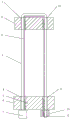
Fig. 1 is a schematic view of the usage state of the fixing structure of the knotting-free loop steel plate with unidirectional locking and pressurizing functions of the present invention.
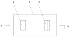
Fig. 2 is the utility model discloses a structural schematic is overlooked of fracture dislocation offside tong "pan" steel sheet among one-way locking pressurization exempts from knot "pan" steel sheet fixed knot structure.
FIG. 3 is a schematic sectional view A-A of FIG. 2.
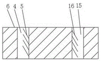
Fig. 4 is a schematic view of the overlooking structure of the side loop steel plate of the surgical incision in the unidirectional locking and pressurizing knotting-free loop steel plate fixing structure of the utility model.
FIG. 5 is a schematic sectional view of the structure of FIG. 4B-B.
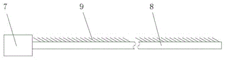
Fig. 6 is a front view structure diagram of the loop line in the unidirectional locking and pressurizing knotting-free loop steel plate fixing structure of the utility model.
Fig. 7 is the structure schematic diagram is looked to the right side of the loop line in the one-way locking pressurization knot-free loop steel plate fixed knot structure of the utility model.
Fig. 8 is a schematic view of a cross-sectional structure of a tail cap in an unidirectional locking and pressurizing knotting-free loop steel plate fixing structure of the present invention.
Detailed Description
The present invention will be further described with reference to the accompanying drawings and embodiments, but the present invention is not limited to this embodiment, and the protection scope of the present invention should be included in all similar structures and similar variations thereof.
Example 1
As shown in figures 1-8, the one-way locking and pressurizing knot-free loop steel plate fixing structure of the utility model comprises a fracture dislocation opposite loop steel plate 3, an operation incision side loop steel plate 6, a loop line and a tail cap 10,
the side loop steel plate 3 at the fracture dislocation is provided with a first through hole 1 and a second through hole 13, two opposite inner side surfaces of the first through hole 1 and the second through hole 13 are respectively provided with at least four first latch teeth 2 and second latch teeth 14 at intervals along the thickness direction of the side loop steel plate 3 at the fracture dislocation, the first latch teeth 2 and the second latch teeth 14 are respectively inclined to the inner side surfaces of the first through hole 1 and the second through hole 13,
the surgical incision side loop steel plate 6 is provided with a third through hole 4 and a fourth through hole 15, the inner side surfaces of the third through hole 4 and the fourth through hole 15 are respectively provided with at least four third latch teeth 5 and four fourth latch teeth 16 in parallel and at intervals along the thickness direction of the surgical incision side loop steel plate 6, the third latch teeth 5 and the fourth latch teeth 16 are respectively inclined to the inner side surfaces of the third through hole 4 and the fourth through hole 15,
the radial section of the main body 8 of the loop thread is flat and oval, one end of the main body 8 of the loop thread is connected with a head end 7, the radial section of the head end 7 is round, the diameter of the radial section of the head end 7 is larger than the major diameter of the radial section of the main body 8, a plurality of fifth clamping teeth 9 are arranged on the side surface of the main body 8 in parallel and at intervals along the length direction of the main body 8, any one of the fifth clamping teeth 9 is inclined to the side surface of the main body 8,
the tail cap 10 is cylindrical, the diameter of the tail cap 10 is larger than the diameters of the third through hole 4 and the fourth through hole 15, the tail cap 10 is provided with a fifth through hole 11, a plurality of sixth latch teeth 12 are arranged on the inner side surface of the fifth through hole 11 at intervals along the thickness direction of the tab line tail cap 10,
the diameter of the tab thread head end 7 is larger than the diameters of the third through hole 4 and the fourth through hole 15, the major diameter of the tab thread main body 8 is smaller than the diameters of the first through hole 1, the second through hole 13, the third through hole 4, the fourth through hole 15 and the fifth through hole 11, the fracture dislocation opposite side tab steel plate 3 and the surgical incision side tab steel plate 6 are oppositely arranged at intervals, the head end 7 of the tab thread is positioned above the surgical incision side tab steel plate 6, the tab thread main body 8 penetrates through the third through hole 4 in the surgical incision side tab steel plate 6 towards the opposite side, then sequentially penetrates through the first through hole 1 and the second through hole 13 in the fracture dislocation opposite side tab steel plate 3 towards the opposite side, then penetrates through the fourth through hole 15 in the surgical incision side tab steel plate 6 towards the surgical incision side, finally penetrates through the fifth through hole 11 in the tail cap 10, and the fifth latch tooth 9 on the tab thread main body 8 sequentially and the third latch tooth 5, the first latch tooth 2, the second latch tooth 14 and the second latch tooth 14 respectively, The fourth latch 16 and the sixth latch 12 are snap locked.
Further, the first through hole 1, the second through hole 13, the third through hole 4, the fourth through hole 15 and the fifth through hole 11 are all rectangular holes.
Furthermore, the side loop steel plate 3 at the fracture dislocation side is in a round corner rectangle shape.
Further, the loop steel plate 6 at the side of the surgical incision is circular.
Further, the first latch 2, the second latch 14, the third latch 5, the fourth latch 16, the fifth latch 9 and the sixth latch 12 are rectangular.
Further, angles formed by the first latch 2 and the inner side surface in the loop thread head end 7 direction of the first through hole 1, the second latch 14 and the inner side surface in the loop thread head end 7 direction of the second through hole 13, the third latch 5 and the inner side surface in the loop thread head end 7 direction of the third through hole 4, the fourth latch 16 and the inner side surface in the loop thread head end 7 direction of the fourth through hole 15, the fifth latch 9 and the side surface in the tail end direction of the loop thread main body 8, and the sixth latch 12 and the inner side surface in the loop thread head end 7 direction of the fifth through hole 11 are all 150 °.
Further, the radial section of the main body 8 of the loop wire is flat ellipse.
Specifically, the thicknesses of the side loop steel plate 3 and the side loop steel plate 6 at the side of the fracture dislocation are both 1.5mm, the lengths of the first through hole 1, the second through hole 13, the third through hole 4, the fourth through hole 15 and the fifth through hole 11 are all 1.2mm, and the widths of the first through hole, the second through hole, the third through hole, the fourth through hole and the fifth through hole are all 0.6 mm. The distance between any two adjacent first latches 2, the distance between any two adjacent second latches 14, the distance between any two adjacent third latches 5, the distance between any two adjacent fourth latches 16, the distance between any two adjacent fifth latches 9, and the distance between any two adjacent sixth latches 12 are all 0.3mm, and the heights of the first latches 2, the second latches 14, the third latches 5, the fourth latches 16, the fifth latches 9, and the sixth latches 12 are all 0.3 mm.
The operation process comprises the following steps: first, as shown in fig. 1, the present loop steel plate fixing structure is assembled into a use state: the loop line main body 8 sequentially passes through a third through hole 4 of an operation incision side steel plate 6, a first through hole 1 of a fracture dislocation opposite side loop steel plate 3, a second through hole 13 of the fracture dislocation opposite side loop steel plate 3 and a fourth through hole 15 of the operation incision side steel plate 6 (note that enough length needs to be reserved between the third through hole 4 and the first through hole 1, and between the second through hole 13 and the fourth through hole 15 according to the thickness of a fracture dislocation joint needing to be fixed in an operation); and the loop thread main body 8 is tensioned along the tail end direction of the loop thread main body 8 below the third through hole 4 of the loop steel plate 6 at the side of the surgical incision, so that the head end 7 of the loop thread is clamped above the third through hole 4 of the loop steel plate 6 at the side of the surgical incision (because the diameter of the head end 7 is larger than that of the third through hole 4), and meanwhile, the fifth latch 9 is meshed and locked with the third latch 5 in the third through hole 4 of the loop steel plate 6 at the side of the surgical incision. Secondly, a through hole penetrating through the side of the operative incision and the opposite side of the fracture dislocation is drilled on a bone (not shown) at the fracture dislocation, the loop steel plate 3 at the opposite side of the fracture dislocation is longitudinally moved along the through hole by using a kirschner wire to completely push the loop steel plate 3 at the opposite side of the fracture dislocation, and then the kirschner wire is used for pushing one end of the loop steel plate 3 at the opposite side of the fracture dislocation, so that the loop steel plate 3 at the opposite side of the fracture dislocation is changed from longitudinal movement to transverse movement to be transversely clamped at the opposite side of the fracture dislocation, and the loop steel plate 3 at the opposite side of the fracture dislocation cannot return to the through hole and the side of the operative incision along the through hole again. Thirdly, the tail end of the loop thread main body 8 is tensioned along the tail end direction of the loop thread main body 8, and then the loop steel plate 6 at the side of the surgical incision, which is occluded and locked with the head end 7 of the loop thread through the third through hole 4, can be closely attached to and placed above the side of the surgical incision of the fracture dislocation; the tail end of the loop line main body 8 is continuously tensioned along the tail end direction of the loop line main body 8, when the loop line main body 8 sequentially penetrates through the first through hole 1 of the fracture dislocation opposite side loop steel plate 3, the second through hole 13 of the fracture dislocation opposite side loop steel plate 3 and the fourth through hole 15 of the operation incision side loop steel plate 6, the fifth latch 9 sequentially and sequentially engages with the first latch 2, the second latch 14 and the fourth latch 16 to form a one-way locking structure, a one-way locking mechanism is formed, four times of progressive pressurization effect are achieved, loss of a pressurizing effect part in a knotting operation process is avoided, and the stability and firmness of fixation are improved. Finally, the tail cap 10 is pushed to the position above the fourth through hole 15 of the loop steel plate 6 close to the side of the surgical incision through the tail end of the loop line main body 8, the tail cap 10 is locked with the tail end of the loop line main body 8 in an occluded mode, the tail end of the loop line main body 8 is fixed, and finally the redundant part of the tail end of the loop line main body 8 is cut off to complete the surgery, so that the tail end of the loop line main body 8 does not need to be knotted, and the local knot foreign body reaction and discomfort caused by too many knotted numbers after the surgery of a patient are reduced.
In addition, adopt absorbable material PLA/PGA copolymer preparation fracture dislocation offside tong steel plate 3, operation incision side tong steel plate 6, tong "pan line and tail cap 10, to the deeper fracture dislocation offside tong steel plate 3 of position can leave over internally and need not take out, avoid fracture dislocation offside tong steel plate 3 to leave over internally to the psychological burden and the spirit misery that the patient caused, need assist new operation incision in fracture dislocation offside when can also avoid taking out internal fixation structure simultaneously and cause secondary damage to the patient.
Claims (7)
1. The utility model provides a one-way locking pressurization knot-free loop steel sheet fixed knot constructs which characterized in that: comprises a fracture dislocation opposite side loop steel plate (3), an operation incision side loop steel plate (6), a loop line and a tail cap (10),
the side loop steel plate (3) at the fracture dislocation is provided with a first through hole (1) and a second through hole (13), two opposite inner side surfaces of the first through hole (1) and the second through hole (13) are respectively provided with at least four first clamping teeth (2) and second clamping teeth (14) at intervals along the thickness direction of the side loop steel plate (3) at the fracture dislocation, the first clamping teeth (2) and the second clamping teeth (14) are respectively inclined to the inner side surfaces of the first through hole (1) and the second through hole (13),
the side loop steel plate (6) of the surgical incision is provided with a third through hole (4) and a fourth through hole (15), the inner side surfaces of the third through hole (4) and the fourth through hole (15) are respectively provided with at least four third latch teeth (5) and four fourth latch teeth (16) in parallel and at intervals along the thickness direction of the side loop steel plate (6) of the surgical incision, the third latch teeth (5) and the fourth latch teeth (16) are respectively inclined to the inner side surfaces of the third through hole (4) and the fourth through hole (15),
the radial section of the main body (8) of the loop wire is in a flat ellipse shape, one end of the main body (8) of the loop wire is connected with a head end (7), the radial section of the head end (7) is in a circle shape, the diameter of the radial section of the head end (7) is larger than the major diameter of the radial section of the main body (8), a plurality of fifth clamping teeth (9) are arranged on the side surface of the main body (8) in parallel and at intervals along the length direction of the main body (8), any one of the fifth clamping teeth (9) is inclined to the side surface of the main body (8),
the tail cap (10) is cylindrical, the diameter of the tail cap (10) is larger than the diameters of the third through hole (4) and the fourth through hole (15), a fifth through hole (11) is arranged on the tail cap (10), a plurality of sixth clamping teeth (12) are arranged on the inner side surface of the fifth through hole (11) at intervals along the thickness direction of the loop line tail cap (10),
the diameter of the loop line head end (7) is larger than the diameters of the third through hole (4) and the fourth through hole (15), the long diameter of the loop line main body (8) is smaller than the diameters of the first through hole (1), the second through hole (13), the third through hole (4), the fourth through hole (15) and the fifth through hole (11), the fracture dislocation contralateral loop steel plate (3) and the surgical incision lateral loop steel plate (6) are oppositely arranged at intervals, the head end (7) of the loop line is positioned above the surgical incision lateral loop steel plate (6), the main body (8) of the loop line penetrates through the third through hole (4) in the surgical incision lateral loop steel plate (6) towards the contralateral side, then sequentially penetrates through the first through hole (1) and the second through hole (13) in the fracture dislocation contralateral loop steel plate (3) towards the contralateral side, then penetrates through the fourth through hole (15) in the surgical incision lateral loop steel plate (6) towards the surgical incision side, and finally penetrates through the fifth through hole (11) in the fifth through cap (10), the fifth latch (9) on the loop line main body (8) is respectively and sequentially meshed and locked with the third latch (5), the first latch (2), the second latch (14), the fourth latch (16) and the sixth latch (12).
2. The one-way locking and pressing knotting-free loop steel plate fixing structure as claimed in claim 1, wherein: the first through hole (1), the second through hole (13), the third through hole (4), the fourth through hole (15) and the fifth through hole (11) are all rectangular holes.
3. The one-way locking and pressing knotting-free loop steel plate fixing structure as claimed in claim 1, wherein: the side loop steel plate (3) at the opposite side of fracture dislocation is in a round corner rectangle shape.
4. The one-way locking and pressing knotting-free loop steel plate fixing structure as claimed in claim 1, wherein: the loop steel plate (6) at the side of the surgical incision is circular.
5. The one-way locking and pressing knotting-free loop steel plate fixing structure as claimed in claim 1, wherein: the first latch (2), the second latch (14), the third latch (5), the fourth latch (16), the fifth latch (9) and the sixth latch (12) are all rectangular.
6. The one-way locking and pressing knotting-free loop steel plate fixing structure as claimed in claim 1, wherein: the angles formed by the inner side surfaces in the directions of the loop wire head ends (7) of the first latch (2) and the first through hole (1), the inner side surfaces in the directions of the loop wire head ends (7) of the second latch (14) and the second through hole (13), the inner side surfaces in the directions of the loop wire head ends (7) of the third latch (5) and the third through hole (4), the inner side surfaces in the directions of the loop wire head ends (7) of the fourth latch (16) and the fourth through hole (15), the side surfaces in the directions of the fifth latch (9) and the tail end of the loop wire main body (8), and the inner side surfaces in the directions of the loop wire head ends (7) of the sixth latch (12) and the fifth through hole (11) are all 150 degrees.
7. The one-way locking and pressing knotting-free loop steel plate fixing structure as claimed in claim 1, wherein: the radial section of the main body (8) of the loop thread is flat and oval.
Priority Applications (1)
| Application Number | Priority Date | Filing Date | Title |
|---|---|---|---|
| CN202022102021.8U CN212438808U (en) | 2020-09-23 | 2020-09-23 | One-way locking pressurization knot-free loop steel plate fixing structure |
Applications Claiming Priority (1)
| Application Number | Priority Date | Filing Date | Title |
|---|---|---|---|
| CN202022102021.8U CN212438808U (en) | 2020-09-23 | 2020-09-23 | One-way locking pressurization knot-free loop steel plate fixing structure |
Publications (1)
| Publication Number | Publication Date |
|---|---|
| CN212438808U true CN212438808U (en) | 2021-02-02 |
Family
ID=74474765
Family Applications (1)
| Application Number | Title | Priority Date | Filing Date |
|---|---|---|---|
| CN202022102021.8U Active CN212438808U (en) | 2020-09-23 | 2020-09-23 | One-way locking pressurization knot-free loop steel plate fixing structure |
Country Status (1)
| Country | Link |
|---|---|
| CN (1) | CN212438808U (en) |
Cited By (1)
| Publication number | Priority date | Publication date | Assignee | Title |
|---|---|---|---|---|
| CN111920508A (en) * | 2020-09-23 | 2020-11-13 | 上海市浦东新区公利医院(第二军医大学附属公利医院) | One-way locking pressurization knot-free loop steel plate fixing structure |
-
2020
- 2020-09-23 CN CN202022102021.8U patent/CN212438808U/en active Active
Cited By (1)
| Publication number | Priority date | Publication date | Assignee | Title |
|---|---|---|---|---|
| CN111920508A (en) * | 2020-09-23 | 2020-11-13 | 上海市浦东新区公利医院(第二军医大学附属公利医院) | One-way locking pressurization knot-free loop steel plate fixing structure |
Similar Documents
| Publication | Publication Date | Title |
|---|---|---|
| US7361179B2 (en) | Sternal closure device and method | |
| US9924937B2 (en) | Knotless suture, and kit containing same | |
| ES2403907T3 (en) | Bearded suture | |
| US20240245399A1 (en) | Indirect attachment of a needle to a mesh suture | |
| EP2229893B1 (en) | Knotless wound closure device | |
| CN105960207B (en) | Recessed surgical fastening device | |
| US20100036415A1 (en) | Surgical needle with reduced contact area | |
| KR20170128472A (en) | Mesh sutures with anti-roping properties | |
| CN212438808U (en) | One-way locking pressurization knot-free loop steel plate fixing structure | |
| KR102109138B1 (en) | Indirect attachment of the needle to the mesh suture | |
| US20170079638A1 (en) | Knotting device and methods of using the same | |
| CN206228413U (en) | Row's button absorptive bundling belt | |
| CN111920508A (en) | One-way locking pressurization knot-free loop steel plate fixing structure | |
| CN206228411U (en) | Reversible lock fixed pattern absorptive bundling belt | |
| CN217592952U (en) | Medical suture line and medical suturing device | |
| CN206518582U (en) | Disposable circumcision stapler | |
| CN214907946U (en) | Medical binding needle and line | |
| CN112244983A (en) | Non-binding fixing belt set for fracture | |
| CN219230087U (en) | Fracture fixing device | |
| WO2019169901A1 (en) | Tendon anti-adhesion membrane for strengthening tendon anastomosis | |
| CN111658053A (en) | Hemostatic buckle | |
| CN221617219U (en) | Anatomical humeral greater knot locking steel plate with low notch | |
| CN215534935U (en) | Nondestructive flexible sternum binding belt with self-locking structure | |
| CN214414899U (en) | Non-binding fixing belt set for fracture | |
| CN215937620U (en) | Hook steel plate internal fixing system for patellar fracture |
Legal Events
| Date | Code | Title | Description |
|---|---|---|---|
| GR01 | Patent grant | ||
| GR01 | Patent grant |