CN212436888U - Trough for livestock breeding - Google Patents
Trough for livestock breeding Download PDFInfo
- Publication number
- CN212436888U CN212436888U CN202020830148.9U CN202020830148U CN212436888U CN 212436888 U CN212436888 U CN 212436888U CN 202020830148 U CN202020830148 U CN 202020830148U CN 212436888 U CN212436888 U CN 212436888U
- Authority
- CN
- China
- Prior art keywords
- water tank
- fixedly connected
- water
- communicated
- trough
- Prior art date
- Legal status (The legal status is an assumption and is not a legal conclusion. Google has not performed a legal analysis and makes no representation as to the accuracy of the status listed.)
- Expired - Fee Related
Links
Images


Landscapes
- Farming Of Fish And Shellfish (AREA)
Abstract
The utility model discloses a trough for livestock-raising, comprising a water tank, fixedly connected with baffle between water tank inner chamber's the top and the bottom, the equal fixedly connected with regulating box in bottom of baffle both sides, the inner chamber of regulating box is provided with the limiting plate, the bottom fixedly connected with spring of limiting plate, the top fixedly connected with telescopic link of limiting plate, the top of water tank is provided with the basin case, the top of telescopic link run through the water tank and with basin case fixed connection, the both sides of water tank bottom all communicate there is the inlet tube. The utility model discloses a set up water tank, baffle, regulating box, limiting plate, spring, telescopic link, basin case, inlet tube, rubber buffer, connecting rod, first hose, water pump, drinking-water pipe, second hose and filter plate, solved current trough for livestock-raising unable automatic watered problem, this trough for livestock-raising possesses automatic watered advantage, is worth promoting.
Description
Technical Field
The utility model relates to a livestock-raising technical field specifically is a trough for livestock-raising.
Background
The livestock breeding utilizes the physiological functions of animals such as livestock and poultry which are domesticated by human beings or wild animals such as deer, musk, fox, marten, otter and quail, and the plants such as pasture grass, feed and the like can be converted into animal energy through artificial breeding to obtain the production departments of livestock products such as meat, eggs, milk, wool, cashmere, skin, silk, medicinal materials and the like.
SUMMERY OF THE UTILITY MODEL
An object of the utility model is to provide a trough for livestock-raising possesses automatic watered advantage, has solved the unable automatic watered problem of current trough for livestock-raising.
In order to achieve the above object, the utility model provides a following technical scheme: a drinking trough for livestock breeding comprises a water tank, wherein a partition plate is fixedly connected between the top and the bottom of an inner cavity of the water tank, adjusting boxes are fixedly connected to the bottoms of the two sides of the partition plate, a limiting plate is arranged in the inner cavity of each adjusting box, a spring is fixedly connected to the bottom of the limiting plate, a telescopic rod is fixedly connected to the top of the limiting plate, a water tank is arranged at the top of the water tank, the top of the telescopic rod penetrates through the water tank and is fixedly connected with the water tank, water inlet pipes are communicated with the two sides of the bottom of the water tank, rubber plugs are arranged at the tops of the water inlet pipes, connecting rods are fixedly connected to the opposite sides of the two telescopic rods and are positioned in the inner cavity of the water tank, one sides of the connecting rods, which are far away from the telescopic rods, are fixedly connected with, the left top fixedly connected with water pump of water tank, the right side intercommunication of water pump has the drinking-water pipe, the right-hand member and the water tank intercommunication of drinking-water pipe, the top intercommunication of water pump has the second hose, the left side fixedly connected with high pressure nozzle of basin incasement chamber, the one end that the second hose kept away from the water pump runs through the basin case and communicates with high pressure nozzle, the bottom fixedly connected with filter plate of basin incasement chamber, the rear side fixedly connected with control box of basin case, the left side fixedly connected with motor of control box, the right side fixedly connected with threaded rod of motor output, the right side of threaded rod runs through to the inner chamber of control box, the right side of threaded rod and the inner wall swing joint of control box, the surface of threaded rod just is located the inner chamber cover of control box and is equipped with the thread bush, the top fixedly connected with dead lever of thread bush, the top of dead lever runs through control box, the front side fixedly connected with cleaning brush of mounting panel bottom, the inner chamber of tank is extended to the bottom of cleaning brush.
Preferably, the both sides of water tank bottom just are located equal fixedly connected with bracing piece between two inlet tubes, the bottom fixedly connected with fixed plate of two bracing pieces.
Preferably, the first opening that uses with the telescopic link cooperation is seted up at the top of regulating box, the surface of telescopic link and the inner chamber cover that is located the water tank are equipped with the sealing washer, the top of sealing washer and the inner wall fixed connection of water tank.
Preferably, the bottoms of the two sides of the water tank are communicated with drain pipes, one end, away from the water tank, of each drain pipe is provided with a pipe cover, and the bottom on the right side of the water tank is communicated with a sewage discharge pipe.
Preferably, the top of the control box is provided with a movable opening matched with the fixed rod for use, and the joint of the right side of the threaded rod and the control box is movably connected through a bearing.
Compared with the prior art, the beneficial effects of the utility model are as follows:
1. the utility model discloses a set up water tank, baffle, regulating box, limiting plate, spring, telescopic link, basin case, inlet tube, rubber buffer, connecting rod, first hose, water pump, drinking-water pipe, second hose and filter plate, solved current trough for livestock-raising unable automatic watered problem, this trough for livestock-raising possesses automatic watered advantage, is worth promoting.
2. The utility model can fill clear water into the water tank by arranging the water inlet pipe, can block the water inlet pipe by arranging the rubber plug, prevents the clear water from being continuously filled into the water tank, the connecting rod can be matched with the telescopic rod to adjust the using position of the rubber plug, the water pump can be matched with the water pumping pipe and the second hose to convey water in the water tank to the high-pressure spray head, the high-pressure spray head can clean the interior of the water tank, the filter plate can prevent impurities from entering the water tank through the first hose, the threaded rod can be matched with the motor to drive the threaded sleeve to move, the threaded sleeve can be matched with the threaded rod to drive the fixed rod to move, through setting up cleaning brush, can clean the impurity of basin incasement portion to blow off pipe department, through setting up the blow off pipe, can discharge the impurity of sweeping out.
Drawings
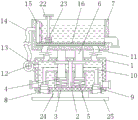
FIG. 1 is a schematic structural view of the present invention;
FIG. 2 is a front view of the structure of the present invention;
fig. 3 is a rear sectional view of the water tank of the present invention.
In the figure: 1. a water tank; 2. a partition plate; 3. an adjusting box; 4. a limiting plate; 5. a spring; 6. a telescopic rod; 7. a water tank; 8. a water inlet pipe; 9. a rubber plug; 10. a connecting rod; 11. a first hose; 12. a water pump; 13. a water pumping pipe; 14. a second hose; 15. a high pressure spray head; 16. filtering the plate; 17. a control box; 18. a motor; 19. a threaded rod; 20. a threaded sleeve; 21. fixing the rod; 22. mounting a plate; 23. a cleaning brush; 24. a support bar; 25. and (7) fixing the plate.
Detailed Description
The technical solutions in the embodiments of the present invention will be described clearly and completely with reference to the accompanying drawings in the embodiments of the present invention, and it is obvious that the described embodiments are only some embodiments of the present invention, not all embodiments. Based on the embodiments in the present invention, all other embodiments obtained by a person skilled in the art without creative work belong to the protection scope of the present invention.
In the description of the present invention, it should be noted that the terms "upper", "lower", "inner", "outer", "front end", "rear end", "both ends", "one end", "the other end", and the like indicate orientations or positional relationships based on the orientations or positional relationships shown in the drawings, and are only for convenience of description and simplification of description, but do not indicate or imply that the device or element to be referred must have a specific orientation, be constructed in a specific orientation, and be operated, and thus, should not be construed as limiting the present invention. Furthermore, the terms "first" and "second" are used for descriptive purposes only and are not to be construed as indicating or implying relative importance.
In the description of the present invention, it is to be noted that, unless otherwise explicitly specified or limited, the terms "mounted", "provided", "connected", and the like are to be construed broadly, such as "connected", which may be fixedly connected, detachably connected, or integrally connected; can be mechanically or electrically connected; they may be connected directly or indirectly through intervening media, or they may be interconnected between two elements. The specific meaning of the above terms in the present invention can be understood in specific cases to those skilled in the art.
Referring to fig. 1-3, a trough for livestock breeding comprises a water tank 1, a partition plate 2 is fixedly connected between the top and the bottom of an inner cavity of the water tank 1, adjusting tanks 3 are fixedly connected to the bottoms of both sides of the partition plate 2, a limiting plate 4 is arranged in the inner cavity of the adjusting tank 3, springs 5 are fixedly connected to the bottoms of the limiting plate 4, telescopic rods 6 are fixedly connected to the tops of the limiting plates 4, a trough tank 7 is arranged at the top of the water tank 1, the top of each telescopic rod 6 penetrates through the water tank 1 and is fixedly connected with the trough tank 7, water inlet pipes 8 are communicated with both sides of the bottom of the water tank 1, rubber plugs 9 are arranged at the tops of the water inlet pipes 8, connecting rods 10 are fixedly connected to the inner cavities of the water tank 1 at opposite sides of the two telescopic rods 6, one side of each connecting rod 10, far away from, the top of the first hose 11 is communicated with the water tank 7, the top of the left side of the water tank 1 is fixedly connected with a water pump 12, the right side of the water pump 12 is communicated with a water pumping pipe 13, the right end of the water pumping pipe 13 is communicated with the water tank 1, the top of the water pump 12 is communicated with a second hose 14, the left side of the inner cavity of the water tank 7 is fixedly connected with a high-pressure spray nozzle 15, one end of the second hose 14, far away from the water pump 12, penetrates through the water tank 7 and is communicated with the high-pressure spray nozzle 15, the bottom of the inner cavity of the water tank 7 is fixedly connected with a filter plate 16, the rear side of the water tank 7 is fixedly connected with a control box 17, the left side of the control box 17 is fixedly connected with a motor 18, the right side of the output end of the motor 18 is fixedly connected with a threaded rod 19, the right side of the threaded rod 19 penetrates through, the top of the thread bush 20 is fixedly connected with a fixed rod 21, the top of the fixed rod 21 penetrates through the control box 17 and is fixedly connected with a mounting plate 22, the front side of the bottom of the mounting plate 22 is fixedly connected with a cleaning brush 23, the bottom of the cleaning brush 23 extends to the inner cavity of the water tank 7, two sides of the bottom of the water tank 1 and the position between the two water inlet pipes 8 are fixedly connected with supporting rods 24, the bottoms of the two supporting rods 24 are fixedly connected with a fixing plate 25, the top of the adjusting box 3 is provided with a first opening matched with the telescopic rod 6 for use, the surface of the telescopic rod 6 and the inner cavity of the water tank 1 are sleeved with a sealing ring, the top of the sealing ring is fixedly connected with the inner wall of the water tank 1, the bottoms of the two sides of the water tank 1 are communicated with a drain pipe, one end of the drain pipe, which is, the right side of the threaded rod 19 is movably connected with the connection part of the control box 17 through a bearing, clear water can be injected into the water tank 1 by arranging the water inlet pipe 8, the water inlet pipe 8 can be blocked by arranging the rubber plug 9, the clear water can be prevented from being continuously injected into the water tank 1, the connecting rod 10 can be matched with the telescopic rod 6 to adjust the using position of the rubber plug 9, the water pump 12 can be matched with the water pumping pipe 13 and the second hose 14 to convey water in the water tank 1 to the high-pressure spray nozzle 15 by arranging the high-pressure spray nozzle 15, the inside of the water tank 7 can be cleaned, impurities can be prevented from entering the water tank 1 through the first hose 11 by arranging the filter plate 16, the threaded rod 19 can be matched with the motor 18 to drive the threaded sleeve 20 to move, the threaded sleeve 20 can be matched with the threaded rod 19 to drive the fixed rod 21 to move, can clean 7 inside impurity in basin case to blow off pipe department, through setting up the blow off pipe, can discharge the impurity of sweeping out, through setting up water tank 1, baffle 2, regulating box 3, limiting plate 4, spring 5, telescopic link 6, basin case 7, inlet tube 8, rubber buffer 9, connecting rod 10, first hose 11, water pump 12, drinking-water pipe 13, second hose 14 and filter plate 16, the unable automatic watered problem of watering of current trough for livestock-raising has been solved, this trough for livestock-raising, possess automatic watered advantage, be worth promoting.
When the water tank is filled with water, the water inlet pipe 8 is opened, the water is filled into the water tank 1, when the water tank 1 is filled with water, the water is filled into the water tank 7 through the first hose 11, when a certain amount of clear water is filled into the water tank 7, the telescopic rod 6 is downwards extruded by the weight of the water tank 7, the telescopic rod 6 is matched with the limiting plate 4 to extrude the spring 5, the telescopic rod 6 moves to drive the connecting rod 10 to move, the connecting rod 10 moves to drive the rubber plug 9 to move, the water inlet pipe 8 is blocked by the rubber plug 9 to prevent the water inlet pipe 8 from being continuously filled with water, when a part of the water in the water tank 7 is consumed, the spring 5 is reset to drive the limiting plate 4 to move, the limiting plate 4 moves to drive the telescopic rod 6 to move, the connecting rod 6 moves to drive the connecting rod 10 to move, the connecting rod 10 moves to drive the, the water pump 12 is started, the water pump 12 conveys water to the high-pressure spray head 15 through the matching of the water pumping pipe 13 and the second hose 14, the high-pressure spray head 15 sprays water to clean the water tank 7, the motor 18 is started simultaneously, the motor 18 drives the threaded rod 19 to rotate, the threaded rod 19 is matched with the threaded sleeve 20 to drive the fixing rod 21 to move, the fixing rod 21 is matched with the mounting plate 22 to drive the cleaning brush 23 to move, and the cleaning brush 23 cleans impurities in the water tank 7 to a drain pipe and discharges the impurities through the drain pipe.
Although embodiments of the present invention have been shown and described, it will be appreciated by those skilled in the art that changes, modifications, substitutions and alterations can be made in these embodiments without departing from the principles and spirit of the invention, the scope of which is defined in the appended claims and their equivalents.
Claims (5)
1. The utility model provides a trough for livestock-raising, includes water tank (1), its characterized in that: a partition plate (2) is fixedly connected between the top and the bottom of an inner cavity of the water tank (1), adjusting tanks (3) are fixedly connected to the bottoms of the two sides of the partition plate (2), limiting plates (4) are arranged in the inner cavity of the adjusting tanks (3), springs (5) are fixedly connected to the bottoms of the limiting plates (4), telescopic rods (6) are fixedly connected to the tops of the limiting plates (4), a water tank (7) is arranged at the top of the water tank (1), the tops of the telescopic rods (6) penetrate through the water tank (1) and are fixedly connected with the water tank (7), water inlet pipes (8) are communicated with the two sides of the bottom of the water tank (1), rubber stoppers (9) are arranged at the tops of the water inlet pipes (8), connecting rods (10) are fixedly connected to one opposite sides of the two telescopic rods (6) and are positioned in the inner cavity of the water tank (1), one side of the connecting rods (10), the water tank is characterized in that the two sides of the top of the water tank (1) are communicated with a first hose (11), the top of the first hose (11) is communicated with the water tank (7), the left top of the water tank (1) is fixedly connected with a water pump (12), the right side of the water pump (12) is communicated with a water pumping pipe (13), the right end of the water pumping pipe (13) is communicated with the water tank (1), the top of the water pump (12) is communicated with a second hose (14), the left side of the inner cavity of the water tank (7) is fixedly connected with a high-pressure nozzle (15), one end, far away from the water pump (12), of the second hose (14) penetrates through the water tank (7) and is communicated with the high-pressure nozzle (15), the bottom of the inner cavity of the water tank (7) is fixedly connected with a filter plate (16), the rear side of the water tank (7) is fixedly connected with a control box (17), and the left side, the right side fixedly connected with threaded rod (19) of motor (18) output, the right side of threaded rod (19) runs through the inner chamber to control box (17), the right side of threaded rod (19) and the inner wall swing joint of control box (17), the surface of threaded rod (19) and the inner chamber cover that is located control box (17) are equipped with thread bush (20), the top fixedly connected with dead lever (21) of thread bush (20), the top of dead lever (21) runs through control box (17) and fixedly connected with mounting panel (22), the front side fixedly connected with cleaning brush (23) of mounting panel (22) bottom, the bottom of cleaning brush (23) extends to the inner chamber of sump tank (7).
2. The trough for livestock breeding of claim 1, characterized in that: the water tank is characterized in that supporting rods (24) are fixedly connected to two sides of the bottom of the water tank (1) and located between the two water inlet pipes (8), and fixing plates (25) are fixedly connected to the bottoms of the two supporting rods (24).
3. The trough for livestock breeding of claim 1, characterized in that: the first opening that uses with telescopic link (6) cooperation is seted up at the top of regulating box (3), the inner chamber cover that the surface of telescopic link (6) just is located water tank (1) is equipped with the sealing washer, the top of sealing washer and the inner wall fixed connection of water tank (1).
4. The trough for livestock breeding of claim 1, characterized in that: the bottom of both sides of the water tank (1) is communicated with a drain pipe, one end of the drain pipe, which is far away from the water tank (1), is sleeved with a pipe cover, and the bottom on the right side of the water tank (7) is communicated with a drain pipe.
5. The trough for livestock breeding of claim 1, characterized in that: the top of control box (17) is seted up the activity opening that uses with dead lever (21) cooperation, the junction of the right side of threaded rod (19) and control box (17) passes through bearing swing joint.
Priority Applications (1)
| Application Number | Priority Date | Filing Date | Title |
|---|---|---|---|
| CN202020830148.9U CN212436888U (en) | 2020-05-18 | 2020-05-18 | Trough for livestock breeding |
Applications Claiming Priority (1)
| Application Number | Priority Date | Filing Date | Title |
|---|---|---|---|
| CN202020830148.9U CN212436888U (en) | 2020-05-18 | 2020-05-18 | Trough for livestock breeding |
Publications (1)
| Publication Number | Publication Date |
|---|---|
| CN212436888U true CN212436888U (en) | 2021-02-02 |
Family
ID=74482852
Family Applications (1)
| Application Number | Title | Priority Date | Filing Date |
|---|---|---|---|
| CN202020830148.9U Expired - Fee Related CN212436888U (en) | 2020-05-18 | 2020-05-18 | Trough for livestock breeding |
Country Status (1)
| Country | Link |
|---|---|
| CN (1) | CN212436888U (en) |
Cited By (1)
| Publication number | Priority date | Publication date | Assignee | Title |
|---|---|---|---|---|
| CN115299370A (en) * | 2022-08-16 | 2022-11-08 | 贵州省种畜禽种质测定中心 | Automatic water feeding device and method for cattle and sheep |
-
2020
- 2020-05-18 CN CN202020830148.9U patent/CN212436888U/en not_active Expired - Fee Related
Cited By (2)
| Publication number | Priority date | Publication date | Assignee | Title |
|---|---|---|---|---|
| CN115299370A (en) * | 2022-08-16 | 2022-11-08 | 贵州省种畜禽种质测定中心 | Automatic water feeding device and method for cattle and sheep |
| CN115299370B (en) * | 2022-08-16 | 2024-01-30 | 贵州省种畜禽种质测定中心 | Automatic water feeding device and method for cattle and sheep |
Similar Documents
| Publication | Publication Date | Title |
|---|---|---|
| CN212436888U (en) | Trough for livestock breeding | |
| CN111587807A (en) | Watering device for livestock breeding | |
| CN216983123U (en) | Cage for breeding poultry | |
| CN210538031U (en) | Livestock breeding device convenient to it is clean | |
| CN211793657U (en) | A shower massage degassing unit for beasts and birds are bred | |
| CN216674247U (en) | Livestock-raising is with trough that possesses self-cleaning function | |
| CN210782500U (en) | Livestock trough easy to clean for livestock breeding | |
| CN112106752A (en) | Efficient pest killing device for livestock breeding and using method | |
| CN215141113U (en) | Disinfection treatment device is bred to pigeon | |
| CN211268109U (en) | Cleaning equipment for livestock breeding | |
| CN214859516U (en) | Automatic sterilization equipment for livestock breeding beef cattle breeding room | |
| CN211214550U (en) | Disinfectant spraying equipment for livestock breeding | |
| CN214257620U (en) | Cleaning device for agricultural greenhouse | |
| CN212660820U (en) | Livestock-raising is with feeding groove | |
| CN210726363U (en) | Novel drinking water device for livestock breeding | |
| CN213281079U (en) | Trough for animal husbandry breeding | |
| CN216452517U (en) | Livestock-raising excrement and urine cleaning device | |
| CN211637631U (en) | Hopper cleaning device for cow breeding | |
| CN213404491U (en) | Watering device for poultry | |
| CN218191531U (en) | Automatic cleaning and disinfecting device for water tank used in colony house breeding | |
| CN215123041U (en) | Practical defecation device for livestock breeding | |
| CN219069143U (en) | Water feeding device for farm | |
| CN218302751U (en) | Cleaning and disinfecting mechanism of breeding cage | |
| CN215302206U (en) | Tibetan incense pig is bred and uses multi-functional colony house | |
| CN215223881U (en) | Constant-temperature drinking trough for cattle breeding |
Legal Events
| Date | Code | Title | Description |
|---|---|---|---|
| GR01 | Patent grant | ||
| GR01 | Patent grant | ||
| CF01 | Termination of patent right due to non-payment of annual fee | ||
| CF01 | Termination of patent right due to non-payment of annual fee |
Granted publication date: 20210202 Termination date: 20210518 |