CN212434788U - Power lead-acid storage battery box - Google Patents
Power lead-acid storage battery box Download PDFInfo
- Publication number
- CN212434788U CN212434788U CN202021379195.2U CN202021379195U CN212434788U CN 212434788 U CN212434788 U CN 212434788U CN 202021379195 U CN202021379195 U CN 202021379195U CN 212434788 U CN212434788 U CN 212434788U
- Authority
- CN
- China
- Prior art keywords
- groove
- utmost point
- electrode
- point post
- pole column
- Prior art date
- Legal status (The legal status is an assumption and is not a legal conclusion. Google has not performed a legal analysis and makes no representation as to the accuracy of the status listed.)
- Active
Links
Images


Classifications
-
- Y—GENERAL TAGGING OF NEW TECHNOLOGICAL DEVELOPMENTS; GENERAL TAGGING OF CROSS-SECTIONAL TECHNOLOGIES SPANNING OVER SEVERAL SECTIONS OF THE IPC; TECHNICAL SUBJECTS COVERED BY FORMER USPC CROSS-REFERENCE ART COLLECTIONS [XRACs] AND DIGESTS
- Y02—TECHNOLOGIES OR APPLICATIONS FOR MITIGATION OR ADAPTATION AGAINST CLIMATE CHANGE
- Y02E—REDUCTION OF GREENHOUSE GAS [GHG] EMISSIONS, RELATED TO ENERGY GENERATION, TRANSMISSION OR DISTRIBUTION
- Y02E60/00—Enabling technologies; Technologies with a potential or indirect contribution to GHG emissions mitigation
- Y02E60/10—Energy storage using batteries
Landscapes
- Secondary Cells (AREA)
Abstract
The utility model provides a lead acid battery box for power, includes battery box and case lid body, and the battery box is including connecting a platform one, side screw post, strengthening post, baffle, electrode slice locating plate, liquid feeding groove, electrode clamp plate pivot, electrode clamp plate all around: the box cover body comprises a pole column groove, a liquid adding hole and a box cover side screw hole, and the pole column groove comprises a pole column groove upper platform, a pole column hole, a pole column groove side plate, a pole column groove screw hole, a pole column groove side plate platform, a pole column groove cover and a connecting platform II; this device uses the baffle to separate into 2 battery jars with the battery box, one puts the negative pole, one is put anodally, then use the electrode slice locating plate to separate 2 battery jars become with the position of electrode piece case adaptation, then insert the electrode slice, the electrode slice at this moment is divided into and inserts into easily, and simultaneously, when reversing also easy roll-off, this device only needs to demolish electrode clamp plate at the in-process of retrieving, can make all electrode pieces roll-off that make, thereby retrieve with convenient classification, it is not waterproof to solve current lead acid battery, meet the water fragile, be difficult to the problem of categorised recovery after damaging.
Description
Technical Field
The utility model relates to the technical field of batteries, concretely relates to lead acid battery box for power.
Background
Lead-acid batteries (Lead-acid batteries) are batteries in which the electrodes are mainly made of Lead and its oxides and the electrolyte is a sulfuric acid solution, and are classified into vented batteries and maintenance-free Lead-acid batteries.
The battery mainly comprises a tubular positive plate, a negative plate, electrolyte, a partition board, a battery jar, a battery cover, a pole, an injection cover and the like. The electrodes of the vented accumulator are made of lead and lead oxide and the electrolyte is an aqueous solution of sulfuric acid. The main advantages are stable voltage and low price; disadvantages are low specific energy (i.e. electrical energy stored per kilogram of battery), short service life and frequent routine maintenance. The old-fashioned common storage battery generally has a service life of about 2 years, and the height of the electrolyte is checked periodically and distilled water is added. However, as technology develops, lead-acid batteries have become longer in life and simpler to maintain.
In the lead-acid storage battery use process, along with the complicated transformation of the use environment, the existing lead-acid storage battery has to be protected well in the use process and cannot be stained with water, particularly, the exposed place of a pole column must be protected well and cannot be used in water, and the lead-acid storage battery is moist and inconvenient to use in places with large dew, so that the lead-acid storage battery with higher moisture resistance is needed. For damaged and unusable batteries, recycling and reuse of lead are of great significance for saving lead resources, enhancing environmental protection and implementing sustainable development strategies. However, if the treatment is not good in the recovery and reuse processes, a new pollution source is inevitably generated, and great harm is caused to the environment and human health. In the process of recycling the existing lead-acid storage battery, due to the arrangement relationship among the battery box, the partition plate and the polar plate, the waste lead-acid storage battery is difficult to separate in the recycling process, and the difficulty of recycling and classifying is caused.
SUMMERY OF THE UTILITY MODEL
An object of the utility model is to provide a lead acid battery case for power solves current lead acid battery and is not waterproof, meets the fragile water, is difficult to the problem of categorised recovery after damaging.
In order to solve the technical problem, the utility model adopts the following technical scheme:
the utility model provides a lead acid battery box for power, includes battery box and case lid body, and the battery box is including connecting a platform one, side screw post, strengthening post, baffle, electrode slice locating plate, liquid feeding groove, electrode clamp plate pivot, electrode clamp plate all around: the box cover body comprises a pole column groove, a liquid adding hole and a box cover side screw hole, and the pole column groove comprises a pole column groove upper platform, a pole column hole, a pole column groove side plate, a pole column groove screw hole, a pole column groove side plate platform, a pole column groove cover and a connecting platform II; the battery box body is arranged to be a rectangular groove, the first connecting table is arranged at the top of the battery box body, the first connecting table is arranged to be a step, the side screw columns are arranged at the top of the side wall of the battery box body, the peripheral reinforcing columns are arranged at four corners of the battery box body, the partition plate is arranged at the center of the battery box body, the electrode plate positioning plates are arranged to be rectangular plates, the electrode plate positioning plates are arranged at the top of the partition plate and the top of the inner wall of the battery box body in pairs, the liquid adding groove is arranged at one end of the partition plate, the electrode pressing plate rotating shaft is arranged on the peripheral reinforcing columns in a switching mode, and the electrode pressing; the polar column groove is arranged at one side edge of the box cover body, the liquid feeding hole is arranged at the other side of the box cover body, the polar column groove upper platform (13) is arranged around the polar column groove, and is arranged at the upper part of the polar column groove, the polar column hole is arranged at the center of the polar column groove and penetrates through the polar column groove, the polar column hole is arranged in a shape matched with the polar column of the battery, the polar column groove side plate is fixedly arranged at the edge of the box cover body and covers half of the depth of the polar column groove, the polar column groove side plate platform is arranged at the opening of the polar column groove above the polar column groove side plate, the polar column groove screw hole is arranged on the polar column groove upper platform and the polar column groove side plate platform, the pole slot cover is arranged into an L-shaped structure matched with the pole slot and embedded in the pole slot upper platform and the pole slot side plate platform, the pole column groove cover is connected with a rubber-wrapped electric wire, and one end of the electric wire is connected to the battery pole column; case lid side screw sets up in the longer both sides of case lid body, connect the inboard that two settings of platform set up at case lid side screw, case lid body lid is established on the battery box, connect a first and connect two case adaptations of platform, establish with connecting a second lid and connect the platform and pass through on connecting the platform one and use screw fixed connection between case lid side screw hole and side screw post.
Furthermore, the width of the electrode pressing plate is set to be one third of that of the electrode plate, a confluence groove is arranged on the electrode pressing plate, and an electrode column hole is formed in one end of the electrode pressing plate.
Furthermore, a central reinforcing column is arranged on the partition plate, threaded holes are formed in the central reinforcing column, and threaded holes are formed in the reinforcing columns on the periphery of the partition plate.
Further, the liquid feeding hole is set to be conical, the bottom of the liquid feeding hole is provided with a first plunger, and the top of the liquid feeding hole is in threaded connection with a second plunger.
Furthermore, a plunger handle is arranged on the first plunger, and a plunger handle is arranged on the second plunger.
Furthermore, the liquid feeding hole is arranged on the central line of the box cover body, and two liquid distributing pipes are symmetrically arranged at the bottom of the box cover body.
Further, utmost point post groove subbed is provided with utmost point post groove bottom, utmost point post groove subbed is provided with the sealing washer.
Further, be provided with the handle groove on the case lid body, handle inslot swivelling joint is provided with the handle, and the center in handle groove still is provided with handle slot hole groove.
Compared with the prior art, the beneficial effects of the utility model are that:
in the device, a battery box body is divided into 2 battery tanks by using a separator, one is used for placing a negative electrode, the other is used for placing a positive electrode, then 2 battery tanks are separated into positions matched with the electrode plate boxes by using the electrode plate positioning plates, then the electrode sheet is inserted, and the electrode sheet is divided to be easily inserted, and is also easily slid out when being overturned, therefore, the top of the battery jar is provided with an electrode pressure plate in a switching way to press the fixed electrode slice so as to prevent the electrode slice from sliding out, in the device, the electrode slice positioning plate can form gaps which facilitate the inflow of solution to soak the whole electrode, and only the electrode pressing plate needs to be removed in the recovery process, all the electrode plates can slide out, so that the electrode plates can be conveniently classified and recovered, and the problem that the conventional lead-acid storage battery and the electrode plates are integrally arranged and are difficult to classify and recover in the recovery process is solved; through the antipole groove, the design change in liquid feeding hole makes whole lead acid battery case can be in the closed condition, in time places whole equipment into the circumstances that the damage also can not appear in the water, has solved current lead acid battery and has not been waterproof, meets the fragile problem of water.
Drawings
Fig. 1 is a front view of the battery box of the present invention.
Fig. 2 is a top view of the battery box of the present invention.
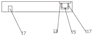
Fig. 3 is a front view of the box cover body of the present invention.
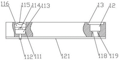
Fig. 4 is a partial sectional view of the front view of the cover body of the present invention.
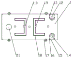
Fig. 5 is a top view of the box cover body of the present invention.
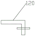
FIG. 6 is the schematic view of the top view pole and the slot cover structure of the box cover body
In the figure, 1-box cover body, 12-pole column groove, 13-pole column groove upper platform, 14-pole column hole, 15-pole column groove side plate, 16-pole column groove screw hole, 17-box cover side screw hole, 18-handle groove, 19-handle groove hole groove, 110-handle, 111-liquid adding hole, 112-liquid separating pipe, 113-first plunger, 114-plunger handle, 115-second plunger, 116-plunger handle, 117-pole column groove side plate platform, 118-pole column groove lower platform, 119-sealing ring, 120-pole column groove cover, 121-connecting platform II, 2-battery box body, 21-connecting platform I, 22-screw column, 23-peripheral reinforcing column, 24-partition plate, 25-electrode plate positioning plate, 26-central reinforcing column, 27-liquid adding groove, 28-electrode pressing plate rotating shaft, 29-electrode pressing plate, 210-central screw thread, 211-electrode column hole and 212-confluence groove.
Detailed Description
In order to make the objects, technical solutions and advantages of the present invention more clearly understood, the present invention is further described in detail below with reference to the accompanying drawings and embodiments. It should be understood that the specific embodiments described herein are merely illustrative of the invention and are not intended to limit the invention.
Example 1:
as shown in the figure, the lead-acid storage battery box for power comprises a battery box body 2 and a box cover body 1, wherein the battery box body 2 comprises a connecting platform I21, side screw columns 22, reinforcing columns 23, a partition plate 24, an electrode plate positioning plate 25, a liquid adding groove 27, an electrode pressing plate rotating shaft 28 and an electrode pressing plate 29: the box cover body 1 comprises a polar column groove 12, a liquid adding hole 111 and a box cover side screw hole 17, wherein the polar column groove 12 comprises a polar column groove upper platform 13, a polar column hole 14, a polar column groove side plate 15, a polar column groove screw hole 16, a polar column groove side plate platform 117, a polar column groove cover 120 and a connecting platform-121; the battery box 2 sets up to rectangular groove, connect a 21 setting and be connected at the top of battery box 2 and battery case lid, connect a 21 setting to the step to make things convenient for the location and the fastening of battery case lid, side screw post 22 sets up and is used for fastening battery box 2 and battery case lid at the lateral wall top of battery box 2. The peripheral reinforcing columns 23 are arranged at four corners of the battery box body 2 to improve the overall supporting strength of the battery box, the partition plate 24 is arranged at the center of the battery box body 2 to distinguish positive and negative electrodes, the electrode plate positioning plate 25 is a rectangular plate to facilitate fastening of electrode plates, the electrode plate positioning plate 25 is arranged at the top of the partition plate 24 and the top of the inner wall of the battery box body 2 in pairs, the liquid adding groove 27 is arranged at one end of the partition plate 24, the electrode plates slide out of the battery box body 2 when the battery box body is reversed, the electrode pressing plate rotating shafts 28 are arranged on the peripheral reinforcing columns 23 in a switching mode, and the electrode pressing plates 29 are fixedly arranged on the electrode pressing plate rotating shafts 28.
Specifically, in this device, utmost point post groove 12 sets up in a side edge of case lid body 1, and utmost point post groove 12 symmetry sets up to 2 and is anodal groove and negative pole groove respectively, the liquid feeding hole sets up the opposite side at case lid body 1. In order to seal the pole column groove well, a pole column groove upper platform 13 is arranged around the pole column groove 12 and is arranged at the upper part of the pole column groove 2, so that a step groove is formed on the box cover body 1, a pole column hole 14 is arranged at the center of the pole column groove 12 and penetrates through the pole column groove 12, a pole column penetrates out of the pole column hole, the pole column hole 14 is in a shape matched with the pole column of the battery, the pole column hole can be preferably arranged in a close contact mode, and a sealing piece can be arranged between the pole column groove upper platform and the pole column groove to seal when necessary. The fixed edge that sets up at case lid body 1 of utmost point post groove curb plate 15 covers half of utmost point post groove 12 degree of depth for the hole has been opened to the side of utmost point post groove 12, utmost point post groove side board platform 117 sets up the utmost point post groove 12 opening part in utmost point post groove side 15 top, utmost point post groove screw 16 sets up on utmost point post groove upper mounting 13 and utmost point post groove side board platform 117, utmost point post groove cover 120 sets up to the L shape structure with utmost point post groove 12 looks adaptation and inlays the setting in utmost point post groove upper mounting 13 and utmost point post groove side board platform 117, the electric wire that is provided with rubber parcel is connected on utmost point post groove cover 120, and electric wire one end is connected on the battery utmost point post, so, when the equipment uses, with the electric wire connection on utmost point post groove cover 120 back on the battery utmost point post, use the screw to cover 120 covers on utmost point post groove 12 is whole sealed. The case cover side screw holes 17 are formed in the longer two sides of the case cover body 1 and used for connecting the whole case cover to the case body. Specifically, the second connecting platform 121 is arranged on the inner side of the box cover side screw hole 17, the box cover body 1 is covered on the battery box body 2, the first connecting platform 21 and the second connecting platform 121 are matched with each other, and the second connecting platform 121 and the first connecting platform 21 are covered and arranged to be fixedly connected through screws between the box cover side screw hole 17 and the side screw column 22. This enables a completely tight fastening of the box.
Thus, in the present device, the battery case is partitioned into 2 battery cells, one for the negative electrode, one for the positive electrode, then 2 battery cases are partitioned into positions fitted with the electrode tab case using the electrode tab positioning plates 25, then the electrode sheet is inserted, and the electrode sheet is divided to be easily inserted, and is also easily slid out when being overturned, therefore, an electrode pressing plate 29 is rotatably provided on the top of the battery case to press the fixed electrode tabs, thereby preventing them from slipping out, in the device, the electrode slice positioning plate 25 forms gaps which facilitate the inflow of solution, such as to soak the whole electrode, and only the electrode pressing plate 29 needs to be removed during the recovery process, can make all the pole pieces roll-off to retrieve with convenient classification, solved current lead acid battery and pole piece and set up as integration, at the in-process of retrieving, be difficult to the problem of categorised recovery.
Through the antipole groove, the design change in liquid feeding hole makes whole lead acid battery box can be in the closed condition, in time places whole equipment and also can not go out the condition of flying the damage if aquatic, has solved current lead acid battery and has not been waterproof, meets the fragile problem of water.
Example 2:
on the basis of the above embodiments, in the present embodiment, in order to not affect the electrode column when fastening the electrode plates, the installation setting of the confluence connecting piece is that the width of the electrode pressing plate 29 is set to be one third of the electrode plates, in order to facilitate the connection of the electrode plates, the electrode pressing plate 29 is provided with the confluence groove 212, and one end of the electrode pressing plate 29 is provided with the electrode column hole 211, so that the installation of the confluence connecting piece and the electrode column is not prevented.
Example 3:
in addition to the above embodiments, in the present embodiment, in order to facilitate the movement of the battery box, the structural strength of the whole battery box needs to be enhanced, so that the partition plate 24 is provided with the center reinforcing column 26, and the center reinforcing column 26 is provided with the screw hole for better fastening with the box cover body 1.
Example 4:
on the basis of the above embodiment, in this embodiment, in order to close the filling hole 111, the filling hole 111 is tapered, the bottom is provided with a first plunger 113, and the top is threadedly provided with a second plunger 115, which is sealed by two plungers.
Example 5:
on the basis of the above embodiments, in this embodiment, in order to facilitate the plunger removal during filling, the first plunger 113 is provided with a plunger handle 114, and the second plunger 115 is provided with a plunger handle 116.
Example 6:
on the basis of the above embodiments, in the present embodiment, the liquid adding hole 111 is disposed on the center line of the box cover body 1, and two liquid separating pipes 112 are symmetrically disposed at the bottom thereof so as to facilitate the simultaneous liquid adding of the positive electrode and the negative electrode.
Example 7:
on the basis of the above embodiment, in this embodiment, the bottom of the pole groove 12 is provided with a pole groove lower stage 118, and the pole groove lower stage 118 is provided with a sealing ring 119 so that the battery pole is automatically sealed under the pressure of connecting with the box body after being installed. Thereby preventing the solution from pouring out.
Example 8:
in addition to the above embodiments, in the present embodiment, in order to facilitate the movement of the whole battery, the case lid body 1 is provided with the handle groove 18, the handle 110 is rotatably provided in the handle groove 18, and the handle groove 18 is further provided with the handle groove hole groove 19 at the center.
Reference throughout this specification to "one embodiment," "another embodiment," "an embodiment," "a preferred embodiment," or the like, means that a particular feature, structure, or characteristic described in connection with the embodiment is included in at least one embodiment described generally in this application. The appearances of the same phrase in various places in the specification are not necessarily all referring to the same embodiment. Further, when a particular feature, structure, or characteristic is described in connection with any embodiment, it is submitted that it is within the scope of the invention to effect such feature, structure, or characteristic in connection with other embodiments.
Although the invention has been described herein with reference to a number of illustrative embodiments thereof, it should be understood that numerous other modifications and embodiments can be devised by those skilled in the art that will fall within the spirit and scope of the principles of this invention. More specifically, various variations and modifications are possible in the component parts and/or arrangements of the subject combination arrangement within the scope of the disclosure, the drawings and the appended claims. In addition to variations and modifications in the component parts and/or arrangements, other uses will also be apparent to those skilled in the art.
Claims (8)
1. The utility model provides a lead acid battery box for power, includes battery box (2) and case lid body (1), its characterized in that: the battery box body (2) comprises a first connecting platform (21), side screw columns (22), peripheral reinforcing columns (23), a partition plate (24), an electrode plate positioning plate (25), a liquid adding groove (27), an electrode pressing plate rotating shaft (28) and an electrode pressing plate (29): the box cover body (1) comprises a pole column groove (12), a liquid adding hole (111) and a box cover side screw hole (17), wherein the pole column groove (12) comprises a pole column groove upper platform (13), a pole column hole (14), a pole column groove side plate (15), a pole column groove screw hole (16), a pole column groove side plate platform (117), a pole column groove cover (120) and a connecting platform II (121); the battery box body (2) is arranged to be a rectangular groove, the first connecting table (21) is arranged at the top of the battery box body (2), the first connecting table (21) is arranged to be a step, the side screw columns (22) are arranged at the top of the side wall of the battery box body (2), the peripheral reinforcing columns (23) are arranged at four corners of the battery box body (2), the partition plates (24) are arranged at the center of the battery box body (2), the electrode plate positioning plates (25) are arranged to be rectangular plates, the electrode plate positioning plates (25) are arranged at the tops of the partition plates (24) and the top of the inner wall of the battery box body (2) in pairs, the liquid adding groove (27) is arranged at one end of the partition plates (24), the electrode pressing plate rotating shaft (28) is arranged on the peripheral reinforcing columns (23) in a switching manner, and the electrode pressing plates (29) are fixedly arranged on the electrode pressing; utmost point post groove (12) set up in one side edge department of case lid body (1), the liquid feeding hole sets up the opposite side at case lid body (1), utmost point post groove upper ledge (13) encircle utmost point post groove (12) and set up the upper portion at utmost point post groove (12), utmost point post hole (14) set up at the center of utmost point post groove (12) and run through utmost point post groove (12), utmost point post hole (14) set up the shape into with battery utmost point post looks adaptation, utmost point post groove curb plate (15) are fixed to be set up in the edge of case lid body (1) and cover half of utmost point post groove (12) degree of depth, utmost point post groove curb plate platform (117) set up utmost point post groove (12) opening part above utmost point post groove curb plate (15), utmost point post groove (16) set up on utmost point post groove upper ledge (13) and utmost point post groove curb plate platform (117), utmost point post groove cover (120) set up to inlay the L shape structure of looks adaptation with utmost point post groove (12) and set up and inlay the screw hole side table (117) and inlay the screw hole platform (117) side table (117) ) The pole groove cover (120) is connected with a rubber-wrapped electric wire, and one end of the electric wire is connected to a battery pole; case lid side screw (17) set up in the longer both sides of case lid body (1), connect two (121) settings of platform in the inboard of case lid side screw (17), case lid body (1) lid is established on battery box (2), connect platform (21) and be connected two (121) case adaptations, with be connected two (121) lids establish on connecting platform (21) through using screw fixed connection between case lid side screw (17) and side screw post (22).
2. A power lead-acid battery pack according to claim 1, wherein: the width of the electrode pressing plate (29) is one third of that of the electrode plate, a confluence groove (212) is arranged on the electrode pressing plate (29), and an electrode column hole (211) is arranged at one end of the electrode pressing plate (29).
3. A power lead-acid battery pack according to claim 1, wherein: the partition plate (24) is provided with a central reinforcing column (26), the central reinforcing column (26) is provided with threaded holes, and the peripheral reinforcing columns (23) are provided with threaded holes.
4. A power lead-acid battery pack according to claim 1, wherein: the liquid adding hole (111) is conical, a first plunger (113) is arranged at the bottom of the liquid adding hole, and a second plunger (115) is arranged at the top of the liquid adding hole in a threaded connection mode.
5. A power lead-acid battery case according to claim 4, wherein: the first plunger (113) is provided with a plunger handle (114), and the second plunger (115) is provided with a plunger handle (116).
6. A power lead-acid battery pack according to claim 1, wherein: the liquid feeding hole (111) is arranged on the central line of the box cover body (1), and two liquid distributing pipes (112) are symmetrically arranged at the bottom of the box cover body.
7. A power lead-acid battery pack according to claim 1, wherein: the bottom of the pole column groove (12) is provided with a pole column groove lower platform (118), and a sealing ring (119) is arranged on the pole column groove lower platform (118).
8. A power lead-acid battery pack according to claim 1, wherein: the box cover is characterized in that a handle groove (18) is formed in the box cover body (1), a handle (110) is rotatably arranged in the handle groove (18), and a handle groove hole groove (19) is formed in the center of the handle groove (18).
Priority Applications (1)
| Application Number | Priority Date | Filing Date | Title |
|---|---|---|---|
| CN202021379195.2U CN212434788U (en) | 2020-07-14 | 2020-07-14 | Power lead-acid storage battery box |
Applications Claiming Priority (1)
| Application Number | Priority Date | Filing Date | Title |
|---|---|---|---|
| CN202021379195.2U CN212434788U (en) | 2020-07-14 | 2020-07-14 | Power lead-acid storage battery box |
Publications (1)
| Publication Number | Publication Date |
|---|---|
| CN212434788U true CN212434788U (en) | 2021-01-29 |
Family
ID=74279004
Family Applications (1)
| Application Number | Title | Priority Date | Filing Date |
|---|---|---|---|
| CN202021379195.2U Active CN212434788U (en) | 2020-07-14 | 2020-07-14 | Power lead-acid storage battery box |
Country Status (1)
| Country | Link |
|---|---|
| CN (1) | CN212434788U (en) |
-
2020
- 2020-07-14 CN CN202021379195.2U patent/CN212434788U/en active Active
Similar Documents
| Publication | Publication Date | Title |
|---|---|---|
| CN207398190U (en) | A kind of alkaline battery cathode sealing structure | |
| CN212434788U (en) | Power lead-acid storage battery box | |
| CN205406658U (en) | Detachable lead acid battery | |
| CN212230521U (en) | Lead-acid storage battery box cover for power | |
| CN213459973U (en) | Lithium ion battery with waterproof function reinforced at joint | |
| CN212230506U (en) | Lead-acid storage battery box for power | |
| CN213782211U (en) | Novel lithium battery composite pole | |
| CN212085062U (en) | Intelligent lithium battery pack device | |
| CN209461593U (en) | A kind of adjustable lithium ion battery | |
| CN209658318U (en) | Rechargeable battery and its charger | |
| CN207098668U (en) | Magnetic-type battery charging and discharging system | |
| CN208507775U (en) | A kind of high-capacity battery | |
| CN201112457Y (en) | Battery box for preventing cell reverse arranging | |
| CN207398253U (en) | A kind of power lithium-ion battery cover board monopole column draws negative end plate square structure | |
| CN200972885Y (en) | Lead-acid battery | |
| CN207530059U (en) | A kind of high magnification aluminum-shell battery | |
| CN210015919U (en) | High-capacity lithium ion battery pack | |
| CN206471418U (en) | A kind of lithium coin cells with energy-gathering ring | |
| CN215418235U (en) | Balanced bottom mass flow structure of cylindrical lithium thionyl chloride battery | |
| CN206412416U (en) | High-current alkaline battery | |
| CN215496942U (en) | Button lithium manganese cell with high sealing performance | |
| CN210984884U (en) | Lithium battery with TYPE-C interface for charging | |
| CN2610501Y (en) | Power type lead-acid storage battery | |
| CN219321409U (en) | Recyclable environment-friendly lithium battery | |
| CN210723251U (en) | High-performance lithium ion battery cell structure |
Legal Events
| Date | Code | Title | Description |
|---|---|---|---|
| GR01 | Patent grant | ||
| GR01 | Patent grant |