CN212424964U - Yarn guide for textile machinery - Google Patents
Yarn guide for textile machinery Download PDFInfo
- Publication number
- CN212424964U CN212424964U CN202020646515.XU CN202020646515U CN212424964U CN 212424964 U CN212424964 U CN 212424964U CN 202020646515 U CN202020646515 U CN 202020646515U CN 212424964 U CN212424964 U CN 212424964U
- Authority
- CN
- China
- Prior art keywords
- yarn guide
- guide groove
- yarn
- baffle
- groove body
- Prior art date
- Legal status (The legal status is an assumption and is not a legal conclusion. Google has not performed a legal analysis and makes no representation as to the accuracy of the status listed.)
- Active
Links
- 239000004753 textile Substances 0.000 title claims abstract description 10
- 238000010276 construction Methods 0.000 abstract description 2
- 238000009987 spinning Methods 0.000 description 3
- 239000004744 fabric Substances 0.000 description 2
- 238000000034 method Methods 0.000 description 2
- 230000009286 beneficial effect Effects 0.000 description 1
- 238000010586 diagram Methods 0.000 description 1
- 238000005516 engineering process Methods 0.000 description 1
- 238000009434 installation Methods 0.000 description 1
- 238000004519 manufacturing process Methods 0.000 description 1
- 230000002035 prolonged effect Effects 0.000 description 1
- 238000009941 weaving Methods 0.000 description 1
Images

Landscapes
- Guides For Winding Or Rewinding, Or Guides For Filamentary Materials (AREA)
Abstract
The utility model discloses a yarn guide for textile machinery, which comprises a fixed base and a yarn guide groove, wherein the fixed base is in threaded connection with the yarn guide groove, the fixed base sequentially comprises a bottom plate, a slide block, a rotating device and a screw sleeve from bottom to top, the yarn guide groove sequentially comprises a screw rod, a yarn guide groove body and a baffle from bottom to top, the bottom plate is provided with a plurality of parallel tracks, the yarn guide groove body is fixedly connected with the screw rod, one end of the baffle is hinged with the yarn guide groove body, and the other end of the baffle is clamped with the yarn guide groove body; the utility model is provided with a plurality of groups of independent yarn guides, can guide a plurality of groups of yarns simultaneously, and the yarn guide groove of the yarn guide is set into an openable structure, when one yarn guide is damaged, the yarn guides of other groups can be directly replaced without stopping the machine, and the working efficiency is not influenced; the height-adjustable of feed carrier, the spiral shell is sheathe in for transparent construction and is provided with the scale mark, can guarantee when changing the feed carrier that the height of feed carrier is unchangeable, does not influence yarn route and yarn tension.
Description
Technical Field
The utility model belongs to the technical field of spinning machine machinery, concretely relates to yarn guide for spinning machine.
Background
In the gauze processing process, yarns need to move among textile machinery according to a set path, so that the gauze textile process is completed. The yarn moves back and forth in the yarn guide hole for a long time, so that the yarn guide is easily worn and scrapped. However, in the prior art, the yarn guide is often provided with only one yarn guide hole and adopts a fixed installation structure, and when the yarn guide is damaged, the whole yarn guide can be replaced by stopping the machine, so that the production efficiency is greatly reduced. CN201820827094.3 discloses a yarn guide with multiple yarn guiding holes, but since the yarn guide is fixedly installed, the changing of the yarn guiding holes will result in the changing of the yarn path, the tension of the yarn is different from the original tension, and further the smoothness and uniformity of the produced fabric are affected. In addition, the yarn guide hole of the yarn guide in the prior art is usually in a totally enclosed structure, so that shutdown operation is needed when the yarn is replaced, and the efficiency is affected.
Disclosure of Invention
An object of the utility model is to provide a yarn guide for spinning machine to solve the problem that exists among the above-mentioned background art, improve weaving technology's work efficiency.
The technical scheme of the utility model is that: the yarn guide for the textile machinery comprises a fixed base and a yarn guide groove, wherein the fixed base is in threaded connection with the yarn guide groove, the fixed base comprises a bottom plate, a sliding block, a rotating device and a threaded sleeve, and the yarn guide groove comprises a screw rod, a yarn guide groove body and a baffle.
The bottom plate is provided with a plurality of parallel tracks, and the sliding block is clamped on the tracks and can freely slide along the tracks. The side face of the bottom of the rotating device is fixedly provided with a plurality of clamping blocks, the top of each sliding block is provided with an annular groove matched with the bottom of the rotating device, each clamping block is clamped in each annular groove, and the rotating device can horizontally rotate along the annular grooves in the sliding blocks.
The swivel nut with rotary device fixed connection, the swivel nut is transparent and the swivel nut outside is vertical to be provided with the scale mark.
One end of the baffle is hinged with the yarn guide groove body, and the other end of the baffle is clamped with the yarn guide groove body.
Furthermore, a rotating handle is arranged on the rotating device.
Furthermore, a yarn guide pad is bonded on the inner hole wall of the yarn guide groove body and the lower part of the baffle.
Has the advantages that:
compared with the prior art, the utility model, following beneficial effect has: the yarn guide for textile machinery of the utility model is provided with a plurality of groups of independent yarn guides, which can guide a plurality of groups of yarns simultaneously; the yarn guide groove of the yarn guide is of an openable structure, when one yarn guide is damaged, the yarn guides of other groups can be directly replaced without stopping the machine, and the working efficiency is not influenced; the height-adjustable of feed carrier, the spiral shell is sheathe in for transparent construction and is provided with the scale mark, can guarantee when changing the feed carrier that the height of feed carrier is unchangeable, does not influence yarn route and yarn tension.
Drawings
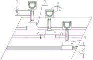
FIG. 1: the utility model has the overall structure schematic diagram;
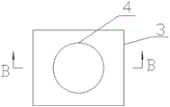
FIG. 2: the view angle a-a structure of fig. 1 is schematic;
FIG. 3: the view angle B-B structure of FIG. 2 is shown schematically.
Illustration of the drawings: 1-bottom plate, 2-track, 3-slide block, 4-rotating device, 5-thread sleeve, 6-screw, 7-yarn guide groove body, 8-baffle, 9-rotating handle rod, 10-annular groove, 11-fixture block and 12-yarn guide pad.
Detailed Description
The utility model provides a yarn guide of textile machinery, including unable adjustment base and yarn guide groove, unable adjustment base and yarn guide groove threaded connection, unable adjustment base includes bottom plate 1, slider 3, rotary device 4, swivel nut 5, the yarn guide groove includes screw rod 6, yarn guide groove body 7, baffle 8.
The bottom plate 1 is provided with a plurality of parallel tracks 2, and the sliding block 3 is clamped on the tracks 2 and can freely slide along the tracks 2. The yarn guide groove is characterized in that a plurality of clamping blocks 11 are fixed on the side face of the bottom of the rotating device 4, an annular groove 10 matched with the bottom of the rotating device 4 is formed in the top of the sliding block 3, the clamping blocks 11 are clamped in the annular groove 10, a rotating handle rod 9 is arranged on the rotating device 4, and when the rotating handle rod 9 is pulled, the rotating device 4 can horizontally rotate along the annular groove 10 on the sliding block 3, so that the angle of the yarn guide groove body is adjusted.
The thread insert 5 is fixedly connected with the rotating device 4, the thread insert 5 is transparent, scale marks are vertically arranged on the outer side of the thread insert 5, the height of the yarn guide groove can be accurately adjusted through the scale marks, and the yarn guide groove is guaranteed to be consistent in height when the yarn guide is replaced.
The yarn guide groove body 7 is fixedly connected with the screw rod 6, one end of the baffle 8 is hinged with the yarn guide groove 7, and the other end of the baffle is clamped with the yarn guide groove 7.
And the inner hole wall of the yarn guide groove body 7 and the lower part of the baffle 8 are bonded with yarn guide pads 12, so that the yarn guide groove is protected from being abraded, and the service life is prolonged.
The utility model discloses during the implementation, suitable position is found to slidable slider 3, adjustment rotary device 4 and screw rod 6. The yarn can be taken out by opening the baffle 8 and the yarn guide groove body 7, and the rotating screw 6 can replace the yarn guide groove of the yarn guide without stopping operation, thereby providing the working efficiency. In addition, the screw-in height of the screw rod can be accurately positioned through the scale marks on the thread insert, so that the tension of the yarn is not influenced when the yarn guide groove is replaced, and the quality of the fabric is ensured.
Claims (3)
1. The utility model provides a yarn guide for textile machinery, includes unable adjustment base and yarn guide groove, unable adjustment base and yarn guide groove threaded connection, unable adjustment base includes bottom plate (1), slider (3), rotary device (4), swivel nut (5), the yarn guide groove includes screw rod (6), yarn guide groove body (7), baffle (8), its characterized in that:
the bottom plate (1) is provided with a plurality of parallel rails (2), the sliding block (3) is clamped on the rails (2), a plurality of clamping blocks (11) are fixed on the side surface of the bottom of the rotating device (4), the top of the sliding block (3) is provided with an annular groove (10) matched with the bottom of the rotating device (4), the clamping blocks (11) are clamped in the annular groove (10), the threaded sleeve (5) is fixedly connected with the rotating device (4), the threaded sleeve (5) is transparent, and scale marks are vertically arranged on the outer side of the threaded sleeve (5);
the yarn guide groove body (7) is fixedly connected with the screw rod (6), the screw rod (6) is in threaded connection with the threaded sleeve (5), one end of the baffle (8) is hinged with the yarn guide groove body (7), and the other end of the baffle is clamped with the yarn guide groove body (7).
2. Yarn guide for textile machines according to claim 1, characterized in that the rotating device (4) is provided with a rotating lever (9).
3. The yarn guide of claim 1, wherein a yarn guide pad (12) is bonded to the inner hole wall of the yarn guide groove body (7) and the lower part of the baffle (8).
Priority Applications (1)
| Application Number | Priority Date | Filing Date | Title |
|---|---|---|---|
| CN202020646515.XU CN212424964U (en) | 2020-04-26 | 2020-04-26 | Yarn guide for textile machinery |
Applications Claiming Priority (1)
| Application Number | Priority Date | Filing Date | Title |
|---|---|---|---|
| CN202020646515.XU CN212424964U (en) | 2020-04-26 | 2020-04-26 | Yarn guide for textile machinery |
Publications (1)
| Publication Number | Publication Date |
|---|---|
| CN212424964U true CN212424964U (en) | 2021-01-29 |
Family
ID=74294958
Family Applications (1)
| Application Number | Title | Priority Date | Filing Date |
|---|---|---|---|
| CN202020646515.XU Active CN212424964U (en) | 2020-04-26 | 2020-04-26 | Yarn guide for textile machinery |
Country Status (1)
| Country | Link |
|---|---|
| CN (1) | CN212424964U (en) |
Cited By (2)
| Publication number | Priority date | Publication date | Assignee | Title |
|---|---|---|---|---|
| CN112978501A (en) * | 2021-02-20 | 2021-06-18 | 泰山玻璃纤维有限公司 | Multifunctional ceramic tension device for glass fiber winding |
| CN114634061A (en) * | 2022-03-17 | 2022-06-17 | 海宁市欧师达染整有限公司 | Yarn guide device for warping |
-
2020
- 2020-04-26 CN CN202020646515.XU patent/CN212424964U/en active Active
Cited By (3)
| Publication number | Priority date | Publication date | Assignee | Title |
|---|---|---|---|---|
| CN112978501A (en) * | 2021-02-20 | 2021-06-18 | 泰山玻璃纤维有限公司 | Multifunctional ceramic tension device for glass fiber winding |
| CN114634061A (en) * | 2022-03-17 | 2022-06-17 | 海宁市欧师达染整有限公司 | Yarn guide device for warping |
| CN114634061B (en) * | 2022-03-17 | 2024-02-20 | 海宁市欧师达经编有限公司 | Yarn guiding device for warping |
Similar Documents
| Publication | Publication Date | Title |
|---|---|---|
| CN212424964U (en) | Yarn guide for textile machinery | |
| CN110713077B (en) | Yarn conveying tension adjusting mechanism of large circular knitting machine | |
| CN207932777U (en) | A kind of textile machinery yarn guide | |
| CN213536868U (en) | Sinle silk conveyor of braider is used in weaving | |
| CN211053143U (en) | Drilling machine for grooved drum shaft | |
| CN101392431B (en) | Warp knitting machine pattern bar traversing device | |
| CN210763656U (en) | Colored fiber yarn guiding device for textile machinery | |
| CN216583493U (en) | Wire feeding mechanism for winding machine | |
| CN216738688U (en) | Lining spindle of chemical fiber two-for-one twister | |
| CN215854394U (en) | High efficiency winder seal wire device | |
| CN207159462U (en) | A kind of automatic yarn guide device | |
| CN212477083U (en) | Sewing machine | |
| CN214496673U (en) | Yarn guide device of single-side high-speed circular knitting machine | |
| CN212955594U (en) | Guide mechanism of jacquard knitting machine | |
| CN213005184U (en) | Center workbench special for production and processing of textile machinery | |
| CN210914715U (en) | Novel yarn guide device of textile machine | |
| CN212832101U (en) | Spinning thread tightness adjusting device | |
| CN221721075U (en) | Yarn guide structure of circular knitting machine | |
| CN213738003U (en) | Doubling winder swing yarn guide device for cellulose fiber dyed fabric | |
| CN221028863U (en) | Positioning mechanism of spinning frame | |
| CN213013315U (en) | Textile thread arranging device | |
| CN213568890U (en) | Yarn guide device used for hosiery machine and convenient to adjust yarn tension | |
| CN216836575U (en) | Automatic bobbin winder equipment for spinning | |
| CN217577799U (en) | Yarn guide frame structure beneficial to threading | |
| CN214362018U (en) | Big pot activity bearing structure of circular knitting machine |
Legal Events
| Date | Code | Title | Description |
|---|---|---|---|
| GR01 | Patent grant | ||
| GR01 | Patent grant | ||
| CP03 | Change of name, title or address | ||
| CP03 | Change of name, title or address |
Address after: 458000 west of the middle section of Heqi Avenue, Qi County, Hebi City, Henan Province Patentee after: Henan Xinrun Textile Co.,Ltd. Country or region after: China Address before: 458000 west of the middle section of Heqi Avenue, Qi County, Hebi City, Henan Province Patentee before: Hebi xingeyuan Daning Technology Co.,Ltd. Country or region before: China |