CN212419569U - Core cooling structure - Google Patents
Core cooling structure Download PDFInfo
- Publication number
- CN212419569U CN212419569U CN202020519576.XU CN202020519576U CN212419569U CN 212419569 U CN212419569 U CN 212419569U CN 202020519576 U CN202020519576 U CN 202020519576U CN 212419569 U CN212419569 U CN 212419569U
- Authority
- CN
- China
- Prior art keywords
- water
- pipe
- base
- water storage
- storage box
- Prior art date
- Legal status (The legal status is an assumption and is not a legal conclusion. Google has not performed a legal analysis and makes no representation as to the accuracy of the status listed.)
- Active
Links
Images


Abstract
The utility model discloses a core cooling structure, including base, lower mould and last mould, lower mould fixed mounting is in the top of base, it sets up to go up the mould the top of lower mould, the inside of lower mould is provided with the water-cooling cavity, all be provided with two installed parts on the lateral wall of the inside both sides of water-cooling cavity, all pass through on the lateral wall of the inside both sides of water-cooling cavity installed part fixed mounting has the shower, two a plurality of apopore, two have been seted up to the impartial interval in one side that the shower is relative, two the opposite side of shower all is provided with the inlet tube, the inside fixed mounting of base has the water storage box, the inside of water storage box is provided with the pump seat, the top fixed mounting of pump seat has the water pump, one side of water pump is provided with the. The utility model discloses a set up a series of structures and make this device have the fast effectual and energy-concerving and environment-protective characteristics of cooling.
Description
Technical Field
The utility model relates to a die casting die technical field specifically is a core cooling structure.
Background
The die-casting die is a tool for casting metal parts, and is a tool for completing a die-casting process on a special die-casting die forging machine. The basic process of die casting comprises the following steps: molten metal is cast at low speed or high speed and filled into the cavity of the mold, the mold has movable cavity surface, and it is pressurized and forged along with the cooling process of the molten metal, so that the shrinkage cavity and shrinkage porosity defects of the blank are eliminated, and the internal structure of the blank reaches the broken crystal grains in the forged state. The comprehensive mechanical property of the blank is obviously improved.
Most of the existing die-casting dies are provided with cooling channels on the inner walls of die cavities, and heat is dissipated through air flow inside the cooling channels after molten metal is injected into the die-casting dies.
SUMMERY OF THE UTILITY MODEL
An object of the utility model is to provide a core cooling structure to solve the problem that proposes among the above-mentioned background art.
In order to achieve the above object, the utility model provides a following technical scheme: a core cooling structure comprises a base, a lower die and an upper die, wherein the lower die is fixedly arranged at the top of the base, the upper die is arranged at the top of the lower die, a water-cooling cavity is arranged inside the lower die, two installation parts are arranged on the side walls of two sides inside the water-cooling cavity, spray pipes are fixedly arranged on the side walls of two sides inside the water-cooling cavity through the installation parts, a plurality of water outlet holes are formed in one opposite side of the two spray pipes at equal intervals, water inlet pipes are arranged on the other side of the two spray pipes, a water storage tank is fixedly arranged inside the base, a pump seat is arranged inside the water storage tank, a water pump is fixedly arranged at the top of the pump seat, a water suction pipe is arranged on one side of the water pump, a water outlet pipe is arranged at the top of the water pump, a sealing pipe sleeve is arranged at the top of the water storage tank, the water storage tank is characterized in that one end of the water outlet pipe, which is positioned outside the water storage tank, is connected with a water delivery pipe, universal pipe connecting sleeves are arranged at two ends of the water delivery pipe, two branch pipes are connected to the two ends of the water delivery pipe through the two universal pipe connecting sleeves respectively, and one ends of the two branch pipes are communicated with one ends of the two water inlet pipes through the two universal pipe connecting sleeves respectively.
Preferably, the base is internally provided with a bent pipe, the bent pipe is positioned on one side of the water storage tank, one end of the bent pipe extends to the bottom end on one side inside the water-cooling cavity, and the other side of the bent pipe extends to the inside of the water storage tank.
Preferably, the bottom of the inside of the water-cooling cavity is provided with a slope, and the slope is inclined from top to bottom towards the left side of the inside of the water-cooling cavity.
Preferably, one side fixed mounting of base inside has the mounting panel, the inside intermediate position department of mounting panel is provided with the bearing, pass through on the mounting panel bearing movable mounting has the pivot, the one end fixed mounting of pivot has the installation cover, the equal fixed mounting in both sides of installation cover has the flabellum, one side fixed mounting of mounting panel has the motor, the other end of pivot passes through the bearing with the output fixed connection of motor.
Preferably, the equal interval is provided with a plurality of ventilation hole on the lateral wall of base both sides, just the ventilation hole all by interior and outer downward sloping setting.
Preferably, the top of the lateral wall of one side of the water storage tank is provided with a water adding pipe through the sealing pipe sleeve, the lower part of the lateral wall of one side of the water storage tank is provided with a water discharging pipe through the sealing pipe sleeve, and the water adding pipe and one end of the water discharging pipe extend to the outer side of the base.
Compared with the prior art, the beneficial effects of the utility model are that: the utility model has the advantages of scientific and reasonable structure, convenient and safe use, water in the water delivery pipe enters the interiors of the two spray pipes through the two branch pipes and the two inlet pipes respectively by controlling the water pump, then the lower die cavity is rapidly radiated in a water-cooling spraying mode, the sprayed water is gathered to the pipe orifice at one end of the curved pipe through the inclined slope and enters the curved pipe, the motor is controlled to drive the rotating shaft to rotate, so that the two fan blades rotate, the water with certain temperature after being sprayed in the curved pipe is cooled by air cooling, the cooled water enters the interior of the water storage box again, the water is pumped into the water-cooling cavity by the water pump to perform heat radiation and cooling treatment on the lower die cavity, and the device has good effect in the heat radiation process and high speed, and can be used for a plurality of times by one-time water supply, energy conservation and environmental protection.
Drawings
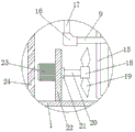
Fig. 1 is a schematic structural view of the whole of the present invention;
FIG. 2 is an enlarged view of the present invention at A in FIG. 1;
fig. 3 is an enlarged view of the present invention at B in fig. 1.
In the figure: 1. a base; 2. a slope; 3. water-cooling the cavity; 4. a lower die; 5. an upper die; 6. a water feeding pipe; 7. a drain pipe; 8. a water storage tank; 9. a water delivery pipe; 10. sealing the pipe sleeve; 11. a pump mount; 12. a water outlet pipe; 13. a water pump; 14. a suction pipe; 15. a curved pipe; 16. a universal pipeline connecting sleeve; 17. a branch pipe; 18. installing a sleeve; 19. a fan blade; 20. a rotating shaft; 21. a bearing; 22. mounting a plate; 23. a motor; 24. a vent hole; 25. a shower pipe; 26. a mounting member; 27. a water outlet hole; 28. and (4) a water inlet pipe.
Detailed Description
The technical solutions in the embodiments of the present invention will be described clearly and completely with reference to the accompanying drawings in the embodiments of the present invention, and it is obvious that the described embodiments are only some embodiments of the present invention, not all embodiments. Based on the embodiments in the present invention, all other embodiments obtained by a person skilled in the art without creative work belong to the protection scope of the present invention.
Referring to fig. 1-3, the present invention provides a technical solution: a technical scheme of a core cooling structure comprises a base 1, a lower die 4 and an upper die 5, wherein the lower die 4 is fixedly arranged at the top of the base 1, the upper die 5 is arranged at the top of the lower die 4, a water-cooling cavity 3 is arranged inside the lower die 4, two mounting parts 26 are respectively arranged on the side walls of the two sides inside the water-cooling cavity 3, spray pipes 25 are respectively fixedly arranged on the side walls of the two sides inside the water-cooling cavity 3 through the mounting parts 26, a plurality of water outlet holes 27 are respectively arranged on the opposite sides of the two spray pipes 25 at equal intervals, water inlet pipes 28 are respectively arranged on the other sides of the two spray pipes 25, a water storage tank 8 is fixedly arranged inside the base 1, a pump seat 11 is arranged inside the water storage tank 8, a water pump 13 is fixedly arranged at the top of the pump seat 11, a water suction pipe 14 is arranged on, the top of outlet pipe 12 extends to the outside of water storage box 8 through sealed pipe box 10, and the one end that outlet pipe 12 is located the water storage box 8 outside is connected with raceway 9, and the both ends of raceway 9 all are provided with universal pipeline adapter sleeve 16, and the both ends of raceway 9 are connected with two branch pipes 17 through two universal pipeline adapter sleeves 16 respectively, and the one end of two branch pipes 17 is respectively through the one end intercommunication of two universal pipeline adapter sleeves 16 and two inlet tubes 28.
Preferably, the base 1 is internally provided with a curved pipe 15, the curved pipe 15 is positioned on one side of the water storage tank 8, one end of the curved pipe 15 extends to the bottom end of one side inside the water-cooling cavity 3, the other side of the curved pipe 15 extends to the inside of the water storage tank 8, the travel of the sprayed water inside the base 1 is prolonged, and the effect of the sprayed water is good when the temperature is reduced.
Preferably, the bottom of the inside of the water-cooling cavity 3 is provided with a slope 2, the slope 2 is inclined from top to bottom towards the left side of the inside of the water-cooling cavity 3, and the sprayed water is collected towards the pipe orifice at one end of the curved pipe 15 and enters the curved pipe 15.
Preferably, a mounting plate 22 is fixedly mounted on one side inside the base 1, a bearing 21 is arranged at the middle position inside the mounting plate 22, a rotating shaft 20 is movably mounted on the mounting plate 22 through the bearing 21, a mounting sleeve 18 is fixedly mounted at one end of the rotating shaft 20, fan blades 19 are fixedly mounted on two sides of the mounting sleeve 18, a motor 23 is fixedly mounted on one side of the mounting plate 22, and the other end of the rotating shaft 20 is fixedly connected with an output end of the motor 23 through the bearing 21.
Preferably, the impartial interval is provided with a plurality of ventilation hole 24 on the lateral wall of base 1 both sides for this device reasonable in design, the fan can be with outside air drum go into to curved pipe and inside have the water of uniform temperature to cool down the heat dissipation and handle, and ventilation hole 24 is all by interior and outer downward sloping setting, can effectually prevent that the dust from getting into the inside of base 1.
Preferably, the water adding pipe 6 is installed above the side wall of one side of the water storage tank 8 through the sealing pipe sleeve 10, the water discharging pipe 7 is installed below the side wall of one side of the water storage tank 8 through the sealing pipe sleeve 10, and one ends of the water adding pipe 6 and the water discharging pipe 7 extend to the outer side of the base 1, so that water can be conveniently supplied to the inside of the water storage tank 8 and water inside the water storage tank 8 can be conveniently discharged.
The working principle is as follows: before use, the safety of each structure of the device is checked firstly, wherein the motor 23 and the water pump 13 are existing electrical elements, the electrical elements can be installed and used according to actual use requirements, the water pump 13 is controlled to pump water into the water delivery pipe 9, the water in the water delivery pipe 9 enters the two spraying pipes 25 through the two branch pipes 17 and the two water inlet pipes 28 respectively, then the lower die 4 die cavity is rapidly radiated in a water-cooling spraying mode, the sprayed water is gathered to the pipe orifice at one end of the curved pipe 15 through the slope 2 and enters the curved pipe 15, the motor 23 is controlled at the moment, the motor 23 drives the rotating shaft 20 to rotate, then the two fan blades 19 rotate, the water with certain temperature after being sprayed into the curved pipe 15 is cooled in an air cooling mode, the cooled water enters the water storage tank 8 again, and then is pumped into the water-cooling die cavity 3 through the water pump 13 to cool the lower die cavity 4, and then make this device effectual at the radiating in-process, fast, and once supply water and can carry out repetitious usage, energy-concerving and environment-protective.
It is noted that, herein, relational terms such as first and second, and the like may be used solely to distinguish one entity or action from another entity or action without necessarily requiring or implying any actual such relationship or order between such entities or actions. Moreover, the terms "comprises," "comprising," or any other variation thereof, are intended to cover a non-exclusive inclusion, such that a process, method, article, or apparatus that comprises a list of elements does not include only those elements but may include other elements not expressly listed or inherent to such process, method, article, or apparatus, and any standard components found in known art that may be commercially available or commercially available and may be readily customized based on the teachings of the specification and the drawings, and that the particular connection between the various components is by conventional means well known in the art, and that the machine, component, or apparatus is by model and circuit connection is by conventional means well known in the art, and will not be described in detail herein.
Although embodiments of the present invention have been shown and described, it will be appreciated by those skilled in the art that changes, modifications, substitutions and alterations can be made in these embodiments without departing from the principles and spirit of the invention, the scope of which is defined in the appended claims and their equivalents.
Claims (6)
1. The utility model provides a core cooling structure, includes base (1), lower mould (4) and goes up mould (5), its characterized in that: the lower die (4) is fixedly installed at the top of the base (1), the upper die (5) is arranged at the top of the lower die (4), the inside of the lower die (4) is provided with a water-cooling cavity (3), two installation parts (26) are arranged on the side walls of the two sides in the water-cooling cavity (3), spray pipes (25) are fixedly installed on the side walls of the two sides in the water-cooling cavity (3), a plurality of water outlet holes (27) are formed in one side, opposite to the spray pipes (25), of each spray pipe (25), a water inlet pipe (28) is arranged on the other side of each spray pipe (25), a water storage box (8) is fixedly installed in the base (1), a pump base (11) is arranged in the water storage box (8), a water pump (13) is fixedly installed at the top of the pump base (11), a water suction pipe (14) is arranged on one side of the water pump (13), the top of water pump (13) is provided with outlet pipe (12), the top of water storage box (8) is provided with sealed pipe box (10), the top of outlet pipe (12) is passed through sealed pipe box (10) extend to the outside of water storage box (8), outlet pipe (12) are located the one end in water storage box (8) outside is connected with raceway (9), the both ends of raceway (9) all are provided with universal pipeline adapter sleeve (16), the both ends of raceway (9) are respectively through two universal pipeline adapter sleeve (16) are connected with two spinal branch pipes (17), two the one end of branch pipe (17) is respectively through two universal pipeline adapter sleeve (16) and two the one end intercommunication of inlet tube (28).
2. The core-cooling structure according to claim 1, wherein: the inside of base (1) is provided with bent pipe (15), bent pipe (15) are located one side of water storage box (8), the one end of bent pipe (15) extends to the bottom of the inside one side of water-cooling cavity (3), the other side of bent pipe (15) extends to the inside of water storage box (8).
3. The core-cooling structure according to claim 1, wherein: the bottom of water-cooling cavity (3) inside is provided with slope (2), slope (2) from top to bottom to the left side slope setting of water-cooling cavity (3) inside.
4. The core-cooling structure according to claim 1, wherein: base (1) inside one side fixed mounting has mounting panel (22), the inside intermediate position department of mounting panel (22) is provided with bearing (21), pass through on mounting panel (22) bearing (21) movable mounting has pivot (20), the one end fixed mounting of pivot (20) has installation cover (18), the equal fixed mounting in both sides of installation cover (18) has flabellum (19), one side fixed mounting of mounting panel (22) has motor (23), the other end of pivot (20) passes through bearing (21) with the output fixed connection of motor (23).
5. The core-cooling structure according to claim 1, wherein: the utility model discloses a ventilation base, including base (1), the equal interval is provided with a plurality of ventilation hole (24) on the lateral wall of base (1) both sides, just ventilation hole (24) all by interior and outer downward sloping setting.
6. The core-cooling structure according to claim 1, wherein: the top of water storage box (8) one side lateral wall is passed through add water pipe (6) are installed in sealing tube sleeve (10), the below of water storage box (8) one side lateral wall is passed through drain pipe (7) are installed in sealing tube sleeve (10), just add water pipe (6) with the one end of drain pipe (7) all extends to the outside of base (1).
Priority Applications (1)
| Application Number | Priority Date | Filing Date | Title |
|---|---|---|---|
| CN202020519576.XU CN212419569U (en) | 2020-04-10 | 2020-04-10 | Core cooling structure |
Applications Claiming Priority (1)
| Application Number | Priority Date | Filing Date | Title |
|---|---|---|---|
| CN202020519576.XU CN212419569U (en) | 2020-04-10 | 2020-04-10 | Core cooling structure |
Publications (1)
| Publication Number | Publication Date |
|---|---|
| CN212419569U true CN212419569U (en) | 2021-01-29 |
Family
ID=74295821
Family Applications (1)
| Application Number | Title | Priority Date | Filing Date |
|---|---|---|---|
| CN202020519576.XU Active CN212419569U (en) | 2020-04-10 | 2020-04-10 | Core cooling structure |
Country Status (1)
| Country | Link |
|---|---|
| CN (1) | CN212419569U (en) |
Cited By (2)
| Publication number | Priority date | Publication date | Assignee | Title |
|---|---|---|---|---|
| CN114054678A (en) * | 2021-10-08 | 2022-02-18 | 安徽贵乾新材料有限公司 | Integrated forming device for processing anode bar and preparation method thereof |
| CN115338390A (en) * | 2022-07-11 | 2022-11-15 | 安徽江南泵阀集团有限公司 | Cooling protection equipment for chemical pump production |
-
2020
- 2020-04-10 CN CN202020519576.XU patent/CN212419569U/en active Active
Cited By (3)
| Publication number | Priority date | Publication date | Assignee | Title |
|---|---|---|---|---|
| CN114054678A (en) * | 2021-10-08 | 2022-02-18 | 安徽贵乾新材料有限公司 | Integrated forming device for processing anode bar and preparation method thereof |
| CN114054678B (en) * | 2021-10-08 | 2024-01-19 | 安徽贵乾新材料有限公司 | Integrated forming device for anode rod machining and preparation method thereof |
| CN115338390A (en) * | 2022-07-11 | 2022-11-15 | 安徽江南泵阀集团有限公司 | Cooling protection equipment for chemical pump production |
Similar Documents
| Publication | Publication Date | Title |
|---|---|---|
| CN212419569U (en) | Core cooling structure | |
| CN214133931U (en) | Casting mould is with high-efficient cooling device | |
| CN110701147A (en) | Heat dissipation assembly for hydraulic pump station | |
| CN111451485B (en) | Water cooling equipment for metal casting | |
| CN214082515U (en) | Automobile charger base injection mold | |
| CN110592345A (en) | Heat treatment equipment for die steel processing production | |
| CN213256710U (en) | Cooling device for stamping die | |
| CN210791962U (en) | Quick cooling device of mould | |
| CN218487178U (en) | Cooling device for die casting die | |
| CN216466030U (en) | Air cooling type injection mold | |
| CN213350777U (en) | Cooling structure of casting die utensil | |
| CN213944763U (en) | Cooling device for forging automobile parts | |
| CN211464795U (en) | Casting device is used in processing of robot valve body | |
| CN211101478U (en) | Continuous casting crystallizer for cast steel | |
| CN209811873U (en) | Water cooling machine for protective cover of numerical control machine tool | |
| CN218906051U (en) | Automobile part forming die | |
| CN219853472U (en) | Cooling device for machining mechanical parts | |
| CN210997798U (en) | Cooling device is used in milling cutter production | |
| CN213353417U (en) | Cooling device is used in automobile mold production | |
| CN219443402U (en) | Metal mold with cooling function | |
| CN210848297U (en) | Intelligent cooling equipment for automatic lathe production products | |
| CN218196784U (en) | Quick heat abstractor of injection mold | |
| CN218395900U (en) | Defoaming device of automobile mold | |
| CN215975959U (en) | Water-cooling and air-cooling dual-purpose gear machining device | |
| CN214557323U (en) | Cooling device with telescopic spray head for casting |
Legal Events
| Date | Code | Title | Description |
|---|---|---|---|
| GR01 | Patent grant | ||
| GR01 | Patent grant |