CN212384029U - Forage reducing mechanism is used in livestock-raising - Google Patents
Forage reducing mechanism is used in livestock-raising Download PDFInfo
- Publication number
- CN212384029U CN212384029U CN202020537061.2U CN202020537061U CN212384029U CN 212384029 U CN212384029 U CN 212384029U CN 202020537061 U CN202020537061 U CN 202020537061U CN 212384029 U CN212384029 U CN 212384029U
- Authority
- CN
- China
- Prior art keywords
- fixedly connected
- forage
- shell
- inlet pipe
- casing
- Prior art date
- Legal status (The legal status is an assumption and is not a legal conclusion. Google has not performed a legal analysis and makes no representation as to the accuracy of the status listed.)
- Expired - Fee Related
Links
Images

Abstract
The utility model discloses a forage reducing mechanism for livestock-raising, which comprises a housin, shells inner wall's top fixedly connected with net bucket, the left side at casing top is run through and is provided with the inlet pipe, the bottom of inlet pipe run through to the inner chamber of casing and with the fixed intercommunication in left side at net bucket top, the both sides at inlet pipe back top all run through and are provided with the bull stick. The utility model provides a current forage reducing mechanism smash the effect poor to the forage, can not carry out abundant smashing to the forage, the longer directness of forage is smashed some simultaneously, the inside winding phenomenon that appears easily of device when smashing, and can not sieve kibbling forage, the great crushing back fodder of volume is fed to adult livestock, and the less forage of volume need be fed to young livestock, the great forage of volume is fed to young livestock, receive the too big forage stab and influence the digestion and absorb easily, thereby influence the problem of growth and development.
Description
Technical Field
The utility model relates to a poultry technical field specifically is a forage reducing mechanism is used in livestock-raising.
Background
The animal husbandry uses the physiological functions of animals such as livestock and poultry which are domesticated by human beings or wild animals such as deer, musk, fox, marten, otter and quail to convert pasture, feed and other plants into animal energy through artificial feeding and reproduction so as to obtain the production departments of animal products such as meat, eggs, milk, wool, cashmere, hide, silk, medicinal materials and the like, which are different from self-sufficient livestock feeding and are mainly characterized in that the pasture and feed are centralized and large-scale and take profit as production purposes, when the livestock eat the forage, the forage is generally firstly crushed and then fed, but the existing forage crushing device has poor effect on crushing the forage, the forage cannot be fully crushed, meanwhile, some forage is directly crushed, the winding phenomenon easily occurs in the crushing device, the crushed forage cannot be sieved, and the adult forage is fed with the large crushed feed, and young livestock needs to feed forage with small volume, and when the young livestock feeds forage with large volume, the young livestock is easily stabbed by the forage with large volume and affects digestion and absorption, thereby affecting growth and development.
SUMMERY OF THE UTILITY MODEL
An object of the utility model is to provide a forage reducing mechanism is used in livestock-raising, it is effectual to possess to smash, be difficult for appearing the advantage of winding and screening, it is poor to the forage crushing effect to have solved current forage reducing mechanism, can not carry out abundant smashing to the forage, the forage is longer directly smashed a bit simultaneously, the winding phenomenon appears easily in device inside when smashing, and can not sieve kibbling forage, the great crushing back fodder of volume is fed to adult livestock, and the less forage of volume need be fed to young livestock, the great forage of volume is fed to young livestock, receive the too big forage stab easily and influence the digestion absorption, thereby influence the problem of growth and development.
In order to achieve the above object, the utility model provides a following technical scheme: a forage smashing device for livestock breeding comprises a shell, wherein a net barrel is fixedly connected to the top of the inner wall of the shell, an inlet pipe is arranged on the left side of the top of the shell in a penetrating mode, the bottom of the inlet pipe penetrates through an inner cavity of the shell and is fixedly communicated with the left side of the top of the net barrel, rotating rods are arranged on two sides of the top of the back of the inlet pipe in a penetrating mode, the front end of each rotating rod penetrates through the inner cavity of the inlet pipe, a cutting disc is fixedly sleeved on the surface of one end, located at the inner cavity of the inlet pipe, of each rotating rod, cutting blades are fixedly connected to the tops of two sides of the inner cavity of the inlet pipe, circular gears are fixedly connected to the rear ends of the rotating rods, the two circular gears are meshed with each other, a U-shaped plate is fixedly connected to the top of the back of the inlet pipe, the left top of the shell is fixedly connected with a second motor, the right end of a rotating shaft of the second motor sequentially penetrates through the shell and the net barrel to extend to an inner cavity of the net barrel and is fixedly connected with a long rod, the right end of the long rod sequentially penetrates through the net barrel and the shell to extend to the outside of the shell and is fixedly connected with a first bevel gear, the surface of the long rod and the inner wall of the net barrel are fixedly connected with a crushing cutter, the inner wall of the shell is fixedly connected with a funnel, the front side and the rear side of the right bottom of the inner cavity of the shell are fixedly connected with a slide bar, the left end of the slide bar is fixedly connected with the left bottom of the inner cavity of the shell, the surfaces of the two ends of the slide bar are movably sleeved with a sleeve, one side of the sleeve is fixedly connected with a screening frame, the left bottom and the, the left side of discharging pipe runs through the inner chamber in square hole and extends to the outside of casing, the right side fixedly connected with framework of screening frame, the right side of framework runs through the inner chamber in rectangular hole and extends to the outside of casing, the front of framework inner chamber and the equal fixedly connected with tooth in the back, the right side fixedly connected with connecting block of casing, the top of connecting block is run through and is provided with the montant, the bottom through connection piece of montant extends to the inner chamber and the fixedly connected with sector gear of framework, tooth and sector gear meshing, the top fixedly connected with second bevel gear of montant, second bevel gear and first bevel gear meshing, the fixed intercommunication in bottom of casing has row material pipe, the bottom fixedly connected with landing leg of casing.
Preferably, the right side of the shell is movably connected with a cover body through a bolt, and the bottom of the supporting leg is fixedly connected with a base.
Preferably, the controller is fixedly connected to the left side of the front face of the casing and is electrically connected with the first motor and the second motor respectively.
Preferably, the bottom of the front side of the shell is movably connected with a box door through a hinge, and the bottom of the front side of the box door is fixedly connected with a handle.
Preferably, be provided with first bearing between bull stick and the inlet pipe, first bearing cover is established on the surface of bull stick, be provided with the second bearing between stock and the net bucket, the second bearing cover is established on the surface of stock, be provided with the third bearing between montant and the connecting block, the third bearing cover is established on the surface of montant.
Preferably, the first through hole that all offers with the adaptation of second motor pivot with the left side of net bucket in the left top of casing, the second through hole with stock looks adaptation is offered to the top on casing right side.
Compared with the prior art, the beneficial effects of the utility model are as follows:
1. the utility model has the advantages of good crushing effect and difficult winding and screening through the cooperation of the shell, the mesh barrel, the feeding pipe, the rotating rod, the cutting disc, the cutting blade, the circular gear, the U-shaped plate, the first motor, the second motor, the long rod, the first bevel gear, the crushing knife, the funnel, the sliding rod, the sleeve, the screening frame, the square hole, the rectangular hole, the discharging pipe, the frame body, the teeth, the connecting block, the vertical rod, the sector gear, the second bevel gear, the discharging pipe and the supporting leg, the utility model solves the problems that the prior grass crushing device has poor crushing effect on grass, can not fully crush the grass, simultaneously can directly crush some grass, easily generates winding phenomenon in the crushing device, can not sieve the crushed grass, feeds crushed feed with larger volume for adult livestock, and young livestock needs to feed grass with smaller volume, when young livestock is fed with forage with larger volume, the forage with larger volume is easy to be stabbed and hurt and influence digestion and absorption, thereby influencing the growth and development.
2. The utility model discloses a set up the cover body, protect the staff, the prevention device causes the damage to the staff, through setting up chamber door and handle, in case when the screening frame blocks up, the staff of being convenient for clears up, through setting up first bearing, fix the bull stick, make the bull stick not receive the influence of inlet pipe when rotating, can not take place to remove simultaneously, through setting up the second bearing, fix the stock, make the stock more stable when rotating, through setting up the third bearing, fix the montant, make the montant not receive the influence of connecting block when rotating, can not reciprocate simultaneously.
Drawings
FIG. 1 is a schematic structural view of the present invention;
FIG. 2 is a schematic top view of the connecting structure of the rotary rod and the circular gear of the present invention;
FIG. 3 is a schematic top view of a portion of the present invention;
fig. 4 is a schematic view of the front view structure of the present invention.
In the figure: the automatic feeding device comprises a shell, a screen barrel, a feeding pipe, a rotating rod, a cutting disc, a cutting blade, a circular gear, a 8U-shaped plate, a first motor, a second motor, a long rod, a first conical gear, a crushing cutter, a funnel, a sliding rod, a sleeve, a 17 screening frame, a square hole, a rectangular hole, a discharging pipe, a frame body, 22 teeth, a connecting block, a 24 vertical rod, a sector gear, a second conical gear, a discharging pipe, a supporting leg, a cover body 29 and a controller 30, wherein the shell is made of a plastic material, the rotating rod is 4, the cutting disc is 5, the.
Detailed Description
The technical solutions in the embodiments of the present invention will be described clearly and completely with reference to the accompanying drawings in the embodiments of the present invention, and it is obvious that the described embodiments are only some embodiments of the present invention, not all embodiments. Based on the embodiments in the present invention, all other embodiments obtained by a person skilled in the art without creative work belong to the protection scope of the present invention.
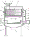
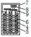
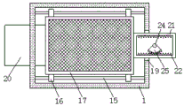
Referring to fig. 1-4, a forage smashing device for livestock breeding comprises a shell 1, a net barrel 2 is fixedly connected to the top of the inner wall of the shell 1, a feeding pipe 3 penetrates through the left side of the top of the shell 1, the bottom of the feeding pipe 3 penetrates through the inner cavity of the shell 1 and is fixedly communicated with the left side of the top of the net barrel 2, rotating rods 4 penetrate through the two sides of the top of the back of the feeding pipe 3, the front end of each rotating rod 4 penetrates through the inner cavity of the feeding pipe 3, a cutting disc 5 is fixedly sleeved on the surface of one end, located at the inner cavity of the feeding pipe 3, of each rotating rod 4, cutting blades 6 are fixedly connected to the tops of the two sides of the inner cavity of the feeding pipe 3, a circular gear 7 is fixedly connected to the rear end of each rotating rod 4, the two circular gears 7 are meshed with each other, a U-shaped plate 8 is fixedly connected to the top of the back of the feeding pipe 3, the top of the left side of the shell 1 is fixedly connected with a second motor 10, the right end of the rotating shaft of the second motor 10 sequentially penetrates through the shell 1 and the mesh barrel 2 to extend to the inner cavity of the mesh barrel 2 and is fixedly connected with a long rod 11, the right end of the long rod 11 sequentially penetrates through the mesh barrel 2 and the shell 1 to extend to the outside of the shell 1 and is fixedly connected with a first bevel gear 12, the surface of the long rod 11 and the inner wall of the mesh barrel 2 are fixedly connected with a crushing knife 13, the inner wall of the shell 1 is fixedly connected with a funnel 14, the front side and the rear side of the right side bottom of the inner cavity of the shell 1 are fixedly connected with a slide rod 15, the left end of the slide rod 15 is fixedly connected with the bottom of the left side of the inner cavity of the shell 1, the surfaces of the two ends of the slide rod 15 are movably sleeved with a sleeve 16, one side of the sleeve 16 is fixedly, the left side of the discharge pipe 20 penetrates through the inner cavity of the square hole 18 and extends to the outside of the shell 1, the right side of the screening frame 17 is fixedly connected with a frame body 21, the right side of the frame body 21 penetrates through the inner cavity of the rectangular hole 19 and extends to the outside of the shell 1, the front side and the back side of the inner cavity of the frame body 21 are both fixedly connected with teeth 22, the right side of the shell 1 is fixedly connected with a connecting block 23, the top of the connecting block 23 is provided with a vertical rod 24 in a penetrating manner, the bottom of the vertical rod 24 penetrates through the connecting block 23 and extends to the inner cavity of the frame body 21 and is fixedly connected with a sector gear 25, the teeth 22 are meshed with the sector gear 25, the top of the vertical rod 24 is fixedly connected with a second bevel gear 26, the second bevel gear 26 is meshed with the first bevel gear 12, the bottom of the shell 1 is fixedly communicated with a discharge, through arranging the cover body 29, the worker is protected, the device is prevented from damaging the worker, the controller 30 is fixedly connected to the left side of the front face of the shell 1, the controller 30 is respectively electrically connected with the first motor 9 and the second motor 10, the bottom of the front face of the shell 1 is movably connected with a box door through a hinge, the bottom of the front face of the box door is fixedly connected with a handle, through arranging the box door and the handle, when the screening frame 17 is blocked, the worker can conveniently clean the screening frame, a first bearing is arranged between the rotating rod 4 and the feeding pipe 3, the first bearing is sleeved on the surface of the rotating rod 4, a second bearing is arranged between the long rod 11 and the net barrel 2, the second bearing is sleeved on the surface of the long rod 11, a third bearing is arranged between the vertical rod 24 and the connecting block 23, the third bearing is sleeved on the surface of the vertical rod 24, the top of the left side of the shell 1 and the left, the second through-hole with stock 11 looks adaptation is seted up at the top on casing 1 right side, through setting up first bearing, it fixes to bull stick 4, make bull stick 4 not receive the influence of inlet pipe 3 when rotating, can not take place to remove simultaneously, through setting up the second bearing, fix stock 11, make stock 11 more stable when rotating, through setting up the third bearing, fix montant 24, make montant 24 not receive the influence of connecting block 23 when rotating, can not reciprocate simultaneously, through casing 1, net bucket 2, inlet pipe 3, bull stick 4, cutting disc 5, cutting blade 6, circular gear 7, U template 8, first motor 9, second motor 10, stock 11, first conical gear 12, crushing sword 13, funnel 14, slide bar 15, sleeve pipe 16, screening frame 17, square hole 18, rectangular hole 19, discharging pipe 20, framework 21, tooth 22, Connecting block 23, the montant 24, sector gear 25, second cone gear 26, arrange material pipe 27 and landing leg 28 and cooperate, it is effectual to possess crushing, the difficult advantage that twines and screening appear, it is poor to forage crushing effect to have solved current forage reducing mechanism, can not carry out fully smashing the forage, simultaneously the longer direct smashing that directly smashes of forage a bit, the inside winding phenomenon that appears easily of device when smashing, and can not sieve kibbling forage, the great crushing back fodder of volume is fed to adult livestock, and the less forage of volume need be fed to young livestock, the great forage of volume is fed to young livestock, receive the too big forage stab and influence digestion absorption easily, thereby influence the problem of growing development.
When the forage smashing machine is used, the smashing device is externally connected with a power supply through a wire, forage is added into the feeding pipe 3, the controller 30 controls the operation of the first motor 9 and the second motor 10, the rotation of the rotating shaft of the first motor 9 drives the rotating rod 4 and the cutting disc 5 to rotate, the rotation of the cutting disc 5 and the fixation of the cutting blade 6 carry out preliminary cutting on the forage, a plurality of forage is prevented from being smashed directly in a long way, the phenomenon of winding in the smashing device can occur, the forage after preliminary cutting enters the mesh barrel 2, the rotation of the rotating shaft of the second motor 10 drives the long rod 11 and the smashing knife 13 on the long rod 11 to rotate, the forage in the mesh barrel 2 is smashed by the rotation of the smashing knife 13 on the long rod 11 and the fixation of the smashing knife 13 on the inner wall of the mesh barrel 2, the forage which is smaller than the aperture of the mesh barrel 2 after smashing falls into the funnel 14 through the mesh barrel 2 and enters the sieving frame 17, the forage which is larger than the aperture of the mesh barrel 2, make the forage smash more abundant, the effect is better, the rotation of stock 11 drives the rotation of first conical gear 12, second conical gear 26 is driven in the rotation of first conical gear 12, montant 24 and sector gear 25's rotation, sector gear 25's rotation drives tooth 22 and framework 21's left and right reciprocating motion, framework 21's left and right reciprocating motion drives and sieves the removal of frame 17, the forage that gets into after smashing is sieved about sieving frame 17, the forage behind the smashing that is less than sieving frame 17 aperture discharges from row material pipe 27 through sieving frame 17, the forage behind the smashing that is greater than sieving frame 17 aperture and is less than net bucket 2 apertures discharges through discharging pipe 20, satisfy and carry out feeding of different forage thicknesses to adult and young section's livestock.
All kinds of parts used in the application document are standard parts and can be purchased from the market, the specific connection mode of all parts adopts conventional means such as mature bolts, rivets, welding and the like in the prior art, the conventional models in the prior art are adopted for machinery, parts and electrical equipment, the conventional connection mode in the prior art is adopted for circuit connection, and detailed description is not given here.
In summary, the following steps: the forage smashing device for livestock breeding comprises a shell 1, a net barrel 2, an inlet pipe 3, a rotating rod 4, a cutting disc 5, a cutting blade 6, a circular gear 7, a U-shaped plate 8, a first motor 9, a second motor 10, a long rod 11, a first bevel gear 12, a smashing knife 13, a funnel 14, a sliding rod 15, a sleeve 16, a sieving frame 17, a square hole 18, a rectangular hole 19, a discharging pipe 20, a frame body 21, teeth 22, a connecting block 23, a vertical rod 24, a sector gear 25, a second bevel gear 26, a discharging pipe 27 and supporting legs 28, and solves the problems that the existing forage smashing device is poor in forage smashing effect, forage cannot fully smash the forage, some forage is long and directly smashed, winding phenomenon easily occurs in the device during smashing, smashed forage cannot be sieved, adult livestock feeds smashed forage, the young livestock needs to feed forage with smaller volume, and when the young livestock feeds forage with larger volume, the young livestock is easily stabbed by the forage with larger volume and affects digestion and absorption, thereby affecting growth and development.
Although embodiments of the present invention have been shown and described, it will be appreciated by those skilled in the art that changes, modifications, substitutions and alterations can be made in these embodiments without departing from the principles and spirit of the invention, the scope of which is defined in the appended claims and their equivalents.
Claims (6)
1. The utility model provides a forage reducing mechanism for livestock-raising, includes casing (1), its characterized in that: the top fixedly connected with net bucket (2) of casing (1) inner wall, the left side at casing (1) top is run through and is provided with inlet pipe (3), the bottom of inlet pipe (3) is run through to the inner chamber of casing (1) and with the fixed intercommunication in left side at net bucket (2) top, the both sides at inlet pipe (3) back top are all run through and are provided with bull stick (4), the front end of bull stick (4) is run through to the inner chamber of inlet pipe (3), the fixed surface cover that bull stick (4) is located inlet pipe (3) inner chamber one end is equipped with cutting disc (5), the top of inlet pipe (3) inner chamber both sides all fixedly connected with cutting blade (6), the rear end fixedly connected with circular gear (7) of bull stick (4), two circular gear (7) mesh each other, the top fixedly connected with U template (8) at inlet pipe (3) back, the right side of the back of the inner cavity of the U-shaped plate (8) is fixedly connected with a first motor (9), the front end of a rotating shaft of the first motor (9) is fixedly connected with the back of a circular gear (7), the left top of the shell (1) is fixedly connected with a second motor (10), the right end of the rotating shaft of the second motor (10) sequentially penetrates through the shell (1) and the net barrel (2) and extends to the inner cavity of the net barrel (2) and is fixedly connected with a long rod (11), the right end of the long rod (11) sequentially penetrates through the net barrel (2) and the shell (1) and extends to the outer part of the shell (1) and is fixedly connected with a first bevel gear (12), the surface of the long rod (11) and the inner wall of the net barrel (2) are fixedly connected with a crushing knife (13), the inner wall of the shell (1) is fixedly connected with a funnel (14), and the front side and the rear side of the right bottom of, the left end of the sliding rod (15) is fixedly connected with the left bottom of the inner cavity of the shell (1), the surfaces of the two ends of the sliding rod (15) are respectively movably sleeved with a sleeve (16), one side of the sleeve (16) is fixedly connected with a screening frame (17), the bottom of the left bottom and the right side of the shell (1) are respectively provided with a square hole (18) and a rectangular hole (19), the left bottom of the screening frame (17) is fixedly communicated with a discharge pipe (20), the left side of the discharge pipe (20) penetrates through the inner cavity of the square hole (18) and extends to the outside of the shell (1), the right side of the screening frame (17) is fixedly connected with a frame body (21), the right side of the frame body (21) penetrates through the inner cavity of the rectangular hole (19) and extends to the outside of the shell (1), the front side and the back side of the inner cavity of the frame body (21) are respectively fixedly connected with teeth (22), and, the top of connecting block (23) is run through and is provided with montant (24), the bottom through connection piece (23) of montant (24) extends to the inner chamber and the fixedly connected with sector gear (25) of framework (21), tooth (22) and sector gear (25) meshing, the top fixedly connected with second conical gear (26) of montant (24), second conical gear (26) and first conical gear (12) meshing, the fixed intercommunication in bottom of casing (1) has row's material pipe (27), the bottom fixedly connected with landing leg (28) of casing (1).
2. The fodder crushing device for livestock breeding according to claim 1, characterized in that: the right side of the shell (1) is movably connected with a cover body (29) through a bolt, and the bottom of the supporting leg (28) is fixedly connected with a base.
3. The fodder crushing device for livestock breeding according to claim 1, characterized in that: the left side fixedly connected with controller (30) on the front of casing (1), controller (30) respectively with first motor (9) and second motor (10) electric connection.
4. The fodder crushing device for livestock breeding according to claim 1, characterized in that: the bottom of the front side of the shell (1) is movably connected with a box door through a hinge, and the bottom of the front side of the box door is fixedly connected with a handle.
5. The fodder crushing device for livestock breeding according to claim 1, characterized in that: be provided with first bearing between bull stick (4) and inlet pipe (3), the surface at bull stick (4) is established to first bearing cover, be provided with the second bearing between stock (11) and net bucket (2), the surface at stock (11) is established to the second bearing cover, be provided with the third bearing between montant (24) and connecting block (23), the surface at montant (24) is established to the third bearing cover.
6. The fodder crushing device for livestock breeding according to claim 1, characterized in that: the first through-hole with second motor (10) pivot looks adaptation is all seted up with the left side of the left top of casing (1) and net bucket (2), the second through-hole with stock (11) looks adaptation is seted up at the top on casing (1) right side.
Priority Applications (1)
| Application Number | Priority Date | Filing Date | Title |
|---|---|---|---|
| CN202020537061.2U CN212384029U (en) | 2020-04-13 | 2020-04-13 | Forage reducing mechanism is used in livestock-raising |
Applications Claiming Priority (1)
| Application Number | Priority Date | Filing Date | Title |
|---|---|---|---|
| CN202020537061.2U CN212384029U (en) | 2020-04-13 | 2020-04-13 | Forage reducing mechanism is used in livestock-raising |
Publications (1)
| Publication Number | Publication Date |
|---|---|
| CN212384029U true CN212384029U (en) | 2021-01-22 |
Family
ID=74257551
Family Applications (1)
| Application Number | Title | Priority Date | Filing Date |
|---|---|---|---|
| CN202020537061.2U Expired - Fee Related CN212384029U (en) | 2020-04-13 | 2020-04-13 | Forage reducing mechanism is used in livestock-raising |
Country Status (1)
| Country | Link |
|---|---|
| CN (1) | CN212384029U (en) |
-
2020
- 2020-04-13 CN CN202020537061.2U patent/CN212384029U/en not_active Expired - Fee Related
Similar Documents
| Publication | Publication Date | Title |
|---|---|---|
| CN210432451U (en) | Quick cutting reducing mechanism of animal forage grass material | |
| CN212384029U (en) | Forage reducing mechanism is used in livestock-raising | |
| CN211538074U (en) | Forage grass feed processing device capable of preventing spraying | |
| CN210641503U (en) | Pasture chopping device for animal husbandry | |
| CN108620203B (en) | Quick feed smashing and mixing device for animal husbandry | |
| CN110959391A (en) | Forage cutting equipment based on mechanical transmission | |
| CN112893090B (en) | Forage processing and treating device for animal husbandry breeding | |
| CN213611598U (en) | Feed processing production apparatus is equipped with rubbing crusher of screening function | |
| CN215353199U (en) | Special fodder mixing machine of raiser | |
| CN213280726U (en) | Livestock-raising is with green fodder reducing mechanism | |
| CN212212009U (en) | Fodder reducing mechanism is used in livestock-raising | |
| CN209609266U (en) | A kind of animal husbandry herbage grinding device | |
| CN208821263U (en) | A kind of livestock-raising is with can pacify fully-charged hay cutter | |
| CN209676916U (en) | A kind of livestock breed aquatics timothy cutter device | |
| CN211793054U (en) | Forage crushing apparatus for livestock breeding | |
| CN212544704U (en) | Continuous smashing device for pasture in animal husbandry | |
| CN218736094U (en) | Forage machine for livestock-raising | |
| CN218277904U (en) | Forage reducing mechanism for poultry | |
| CN218789221U (en) | Corn stalk crushing apparatus for animal husbandry | |
| CN214708897U (en) | Efficient yak is bred and uses forage grass reducing mechanism | |
| CN216123524U (en) | Feed processing production apparatus is equipped with rubbing crusher of material filtering and screening function | |
| CN211931455U (en) | Forage cutting device for livestock production | |
| CN216058369U (en) | Forage comminution device for livestock-raising with collect function | |
| CN219876920U (en) | Forage grass rubbing crusher | |
| CN212065639U (en) | Livestock-raising is with device of throwing something and feeding |
Legal Events
| Date | Code | Title | Description |
|---|---|---|---|
| GR01 | Patent grant | ||
| GR01 | Patent grant | ||
| CF01 | Termination of patent right due to non-payment of annual fee |
Granted publication date: 20210122 Termination date: 20210413 |
|
| CF01 | Termination of patent right due to non-payment of annual fee |