CN212348370U - Multi-strengthening multi-flow-guide mixing barrel structure for hot mixer - Google Patents
Multi-strengthening multi-flow-guide mixing barrel structure for hot mixer Download PDFInfo
- Publication number
- CN212348370U CN212348370U CN202021054089.7U CN202021054089U CN212348370U CN 212348370 U CN212348370 U CN 212348370U CN 202021054089 U CN202021054089 U CN 202021054089U CN 212348370 U CN212348370 U CN 212348370U
- Authority
- CN
- China
- Prior art keywords
- mixing barrel
- shell
- barrel
- valve core
- shaped
- Prior art date
- Legal status (The legal status is an assumption and is not a legal conclusion. Google has not performed a legal analysis and makes no representation as to the accuracy of the status listed.)
- Active
Links
Images


Landscapes
- Accessories For Mixers (AREA)
Abstract
The utility model discloses a multi-strengthening multi-diversion mixing barrel structure for a hot mixer, wherein two diversion structures which are distributed in a central symmetry way relative to the axis of a mixing barrel are fixedly arranged on the inner side wall of the mixing barrel; the water conservancy diversion structure includes: the fan-shaped upper sealing plate is covered on the top of the V-shaped plate, and the fan-shaped lower sealing plate is covered on the bottom of the V-shaped plate; the V-shaped plate is vertically arranged, the edges of the left end and the right end are respectively tightly attached and sealed and fixed on the inner side wall of the mixing barrel, and the arc-shaped edge of the upper sealing plate and the arc-shaped edge of the lower sealing plate are tightly attached and sealed and fixed on the inner side wall of the mixing barrel; the parts which are alloyed by surface laser are arranged on the outer surface of the diversion structure and from the lower section of the mixing barrel to the barrel bottom of the mixing barrelAl with the thickness of 0.5-1.3 mm obtained after treatment2O3A ceramic alloy reinforced wear-resistant layer; al from lower section of mixing barrel to barrel bottom of mixing barrel2O3The coating height of the ceramic alloy reinforced wear-resistant layer is 1/4-2/5 of the height of the materials when the maximum mixed materials are placed in the mixing barrel. The structure is simple, the material mixing uniformity is good, and the service life is long.
Description
Technical Field
The utility model relates to a compounding technical field especially relates to hot mixer is with strengthening more and leading a class compounding bucket structure.
Background
The rapid development of plastic, chemical, medicine and food industries drives the rapid development of mixing technology and mixing equipment, and in recent years, along with the continuous research and development and application of new technologies, the production efficiency of the mixing equipment is generally and rapidly improved.
Vertical hot mixer utilizes centrifugal force and gravity to stir the even compounding equipment of misce bene with more than two kinds of materials, and the structure of common vertical hot mixer in the existing market includes: the mixing barrel is fixedly arranged on the frame, and the barrel cover is hermetically covered at the barrel opening of the mixing barrel; be provided with the water conservancy diversion structure on the inside wall of compounding bucket, be provided with the agitating unit that can stir the mixture to the material in the inner chamber of compounding bucket bottom the compounding bucket. The compounding bucket adopts ordinary stainless steel material basically, and this kind of material has higher corrosion resistance, but the wearability is poor, and wearing and tearing are one of the leading reasons of inefficacy of compounding bucket and water conservancy diversion structure, and the economic loss who causes because of wearing and tearing annually accounts for the overwhelming majority, and the energy cost who consumes is increasing day by day, and how to improve the wearability of compounding bucket and water conservancy diversion structure is the current problem that awaits a urgent need to solve. The service life of the material is 1-2 years under general conditions. When there are materials with higher hardness such as: the service life of high-concentration CaCO3, glass fiber, glass beads and the like is shorter than that of the glass fiber, glass beads and the like in general, so that the method cannot be suitable for occasions with high-hardness material mixing and stirring requirements.
SUMMERY OF THE UTILITY MODEL
The utility model discloses the technical problem that needs to solve is: the utility model provides a hot mixer is with many reinforcings many water conservancy diversion compounding bucket structures of simple structure, material mixing degree of consistency are good, long service life.
In order to solve the above problem, the utility model adopts the following technical scheme: many water conservancy diversion compounding bucket structures are reinforceed with many to hot mixer, include: the mixing barrel is fixedly provided with two flow guide structures on the inner side wall of the mixing barrel, and the two flow guide structures are distributed on the inner side wall of the mixing barrel in a centrosymmetric manner relative to the axis of the mixing barrel; each flow guide structure comprises: the fan-shaped upper sealing plate is covered at the top of the V-shaped plate, the fan-shaped lower sealing plate is covered at the bottom of the V-shaped plate, and the upper sealing plate and the lower sealing plate are both horizontally arranged; the V-shaped plate is vertically arranged, the edge of the left end and the edge of the right end are tightly attached and sealed and fixed on the inner side wall of the mixing barrel, the arc-shaped edge of the upper sealing plate and the arc-shaped edge of the lower sealing plate are tightly attached and sealed and fixed on the inner side wall of the mixing barrel, and therefore a hollow closed cavity is formed among the upper sealing plate, the V-shaped plate, the lower sealing plate and the inner side wall of the mixing barrel; al obtained after surface laser alloying treatment is arranged on the outer surface of the diversion structure and from the lower section of the mixing barrel to the barrel bottom of the mixing barrel2O3Ceramic alloy reinforced wear-resistant layer, Al2O3The thickness of the ceramic alloy reinforced wear-resistant layer is 0.5-1.3 mm; al from lower section of mixing barrel to barrel bottom of mixing barrel2O3The coating height of the ceramic alloy reinforced wear-resistant layer is 1/4-2/5 of the height of the materials when the maximum mixed materials are placed in the mixing barrel.
Further, the hot mixer is with many reinforcings many water conservancy diversion compounding bucket structures, wherein, the lower section of compounding bucket is to the Al of compounding bucket barrel head2O3The coating height of the ceramic alloy reinforced wear-resistant layer is 1/3 of the material height when the maximum mixed material is placed in the mixing barrel.
Further, the multi-reinforcement multi-diversion mixing barrel structure for the hot mixer comprises a cylindrical barrel, an arc-shaped curved surface and a barrel bottom, wherein the barrel bottom is in sealed and smooth transitional connection with the edge of the lower end of the arc-shaped curved surface, and the edge of the upper end of the arc-shaped curved surface is in sealed and smooth transitional connection with an open port at the bottom of the barrel.
Further, the multi-reinforced multi-flow-guide mixing barrel structure for the hot mixer is characterized in that a side discharge port communicated with an inner cavity of the mixing barrel is formed in the side wall of the bottom end of the mixing barrel, and the side discharge port is connected with a discharge pipe through a side discharge sealing device; the structure of the side discharging sealing device comprises: the side discharge port is hermetically connected to the connecting flange through the front end flange, so that the side discharge port is hermetically communicated with an inner cavity of the shell; the bottom end face of the shell is opened to form a rectangular opening, the feed inlet of the discharge pipe is a rectangular feed inlet matched with the rectangular opening, the discharge outlet of the discharge pipe is a circular discharge outlet, and the rectangular feed inlet of the discharge pipe is communicated with the rectangular opening in a sealing manner; the front end of the cylinder body of the horizontally placed cylinder is fixedly arranged in the mounting through hole on the rear end surface of the shell, the extension rod of the cylinder is positioned in the inner cavity of the shell, and the front end of the extension rod of the cylinder is fixedly connected with the hollow valve core; the outer side surface of the valve core is a conical surface with a small front end diameter and a large rear end diameter, a shaft collar protruding outwards is arranged on the conical surface at the rear end of the valve core, and a first sealing groove circumferentially surrounding a circle is formed at the joint of the conical surface of the valve core and the shaft collar; the inner hole wall of the front end flange and the inner hole wall of the connecting flange form a complete conical channel matched with the conical surface of the valve core, a second sealing groove which surrounds the conical channel by a circle is formed inwards at the rear end of the conical channel, and the first sealing ring is embedded in the second sealing groove; when an extension rod of the cylinder extends forwards to enable the valve core to move forwards until the conical surface of the valve core is tightly attached to the conical channel to form a first seal, the first seal groove is tightly attached to the first seal ring to form a second seal, so that the side discharge port is sealed doubly; when the extension rod of the cylinder retracts backwards, the valve core can be pulled to move backwards, and the side discharging port is opened.
Further, in the aforementioned multi-reinforcement multi-diversion mixing barrel structure for a thermal mixer, a horizontally disposed guide rod is disposed on each of the left and right sides of an extension rod of the cylinder, the front end of each guide rod is fixedly connected to the valve core, the rear end of each guide rod passes through a corresponding rear end through hole on the rear end face of the casing and then extends out of the casing, a second seal ring is disposed in the corresponding rear end through hole, and each guide rod is sealed by the corresponding second seal ring and movably inserted into the corresponding rear end through hole.
Further, the multi-reinforcement multi-diversion mixing barrel structure for the hot mixer is characterized in that a plurality of air inlet quick-plug connectors are fixedly arranged at the top end of the shell, air inlets of the air inlet quick-plug connectors are connected with an air source with pressure, and air outlets of the air inlet quick-plug connectors extend into an inner cavity of the shell through corresponding top through holes in the top surface of the shell; when the valve core is in a state of opening the side discharging port, the air outlet of each air inlet quick connector is respectively used for blowing the surface of the valve core, the surface of the extending rod of the air cylinder, the surface of each guide rod and the inner cavity wall of the shell.
Further, aforementioned many water conservancy diversion compounding bucket structures are reinforceed to hot mixer more, wherein, offer the access hole with casing inner chamber intercommunication on shell top surface, be provided with sealed the pad in access hole department, the apron left end articulates on the shell top surface of access hole left end, the apron rotates to cover behind the access hole around the pin joint of apron and shell top surface, through sealed pad and fastener sealing cover in access hole department.
Further, aforementioned hot-mix machine is with many reinforcings many water conservancy diversion compounding bucket structure, wherein, still be provided with the baffle on the casing left surface, the baffle top is higher than the casing top, and when the apron rotated to propping against the baffle around the pin joint on apron and casing top, through the baffle supporting apron, made the apron maintain in this position.
Further, in the aforementioned multiple reinforced multiple diversion mixing barrel structure for a hot mixer, at least one inner cavity wall on the left inner cavity wall of the casing is punched outward to form a first horizontal strip-shaped protrusion protruding outward, and at least one inner cavity wall on the right inner cavity wall of the casing is punched outward to form a second horizontal strip-shaped protrusion protruding outward.
Further, the multi-reinforcement multi-flow-guide mixing barrel structure for the hot mixer is characterized in that the taper alpha 1 of the conical surface of the valve core is 10-15 degrees; the included angle alpha 2 between the axis of the discharging pipe and the horizontal plane is 45-60 degrees.
The utility model has the advantages that:when the two guide structures which are arranged in central symmetry are matched with a stirring device in the inner cavity of the mixing barrel for use, the materials can be better guided to do parabolic motion, the uniformity of material mixing can be improved, the materials can be prevented from accumulating and attaching to the inner side wall of the mixing barrel, and the uniformity of material mixing can reach more than 99.9%; secondly, Al obtained after surface laser alloying treatment is arranged on the outer surface of the flow guide structure and from the lower section of the mixing barrel to the barrel bottom of the mixing barrel2O3Ceramic alloy reinforced wear-resistant layer, Al2O3The ceramic alloy reinforced wear-resistant layer is a toughened coating with good wear resistance and corrosion resistance, the hardness can reach 440.8HV0.1, the surface volume wear rate is about 10.6mm3/m 2. h, the service life of the mixing barrel and the flow guide structure is greatly prolonged, and the maintenance cost is reduced; when the side discharge port is blocked by the valve core in a sealing way, and the conical surface of the valve core is tightly attached to the conical channel to form a first seal, the first seal groove is tightly attached to the first seal ring to form a second seal, so that the sealing effect of the side discharge sealing device is greatly improved by the double sealing structure; and the air inlet quick connectors are used for blowing the surfaces of the valve core, the extending rod of the air cylinder, the guide rods and the inner cavity wall of the shell, and blowing off the materials attached to the surfaces of the valve core, the extending rod of the air cylinder, the guide rods and the inner cavity wall of the shell, so that the sealing effect of the side discharging sealing device is further improved.
Drawings
Fig. 1 is a schematic structural view of a multi-reinforced multi-flow-guiding mixing barrel structure for a hot mixer of the present invention.
Fig. 2 is a partial internal structure schematic diagram of the mixing bowl.
Fig. 3 is a schematic view of the structure in the top view of fig. 2.
Fig. 4 is a schematic structural view of a flow guide structure.
Fig. 5 is a schematic view of the outer structure of the mixing bowl in the left-hand direction of fig. 1.
Fig. 6 is a schematic view of the internal structure of the side discharge sealing device in fig. 5.
Fig. 7 is a partially enlarged structural view of a portion a in fig. 6.
Fig. 8 is a schematic view of the valve cartridge of fig. 6.
Fig. 9 is a schematic view of the internal structure in the top view of fig. 6.
Detailed Description
The technical solution of the present invention will be described in further detail with reference to the accompanying drawings and preferred embodiments.
This embodiment hot mixer with reinforce many water conservancy diversion compounding bucket structure more, include: mixing barrel 1, mixing barrel 1 is fixed to be set up in the frame of hot mixer. In actual operation, usually put into mixing bucket 1 with the auxiliary material according to the proportion of process formula, then start the hot mixer, the mixing bucket starts for the area material, cause drive arrangement load to start, this can lead to hot mixer to produce vibrations when starting, especially large-scale hot mixer vibrations phenomenon is more obvious, be provided with the antivibration packing ring of being made by mixing pore structure polyurethane material in the junction between mixing bucket 1 and the frame in this embodiment, this antivibration packing ring has the better shock-absorbing function of inhaling, effectively reduce the vibrations that the hot mixer produced when starting.
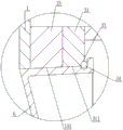
As shown in fig. 2, the mixing bowl 1 of the present embodiment includes: the barrel comprises a cylindrical barrel body 11, an arc-shaped curved surface 13 and a barrel bottom 12, wherein the barrel bottom 12 is in sealed smooth transition connection with the edge of the lower end of the arc-shaped curved surface 13, and the edge of the upper end of the arc-shaped curved surface 13 is in sealed smooth transition connection with an open port at the bottom of the barrel body 11. The cylindrical barrel 11, the arc-shaped curved surface 13 and the barrel bottom 12 can be formed by integral molding, and the cylindrical barrel 11, the arc-shaped curved surface 13 and the barrel bottom 12 can also be connected by welding.
As shown in fig. 1, fig. 2, fig. 3 and fig. 4, two flow guide structures 2 are fixedly arranged on an inner side wall 11 of the mixing bowl 1, and the two flow guide structures 2 are centrally and symmetrically distributed on the inner side wall 11 of the mixing bowl 1 relative to an axis of the mixing bowl. Each flow guiding structure 2 comprises: the V-shaped plate that constitutes by left side board 23 and right side board 24, fan-shaped's last shrouding 21 closing cap in V-shaped plate top, fan-shaped's lower shrouding 22 closing cap in V-shaped plate bottom, and go up shrouding 21 and the equal level setting of shrouding 22 down. V-shaped plate is vertically placed, the edge of the left end and the edge of the right end are tightly attached to and sealed and fixed on the inner side wall 11 of the mixing barrel 1, and the arc-shaped edge of the upper sealing plate 21 and the arc-shaped edge of the lower sealing plate 22 are tightly attached to and sealed and fixedIs fixed on the inner side wall 11 of the mixing barrel 1, so that a hollow closed cavity 20 is formed between the upper closing plate 21, the V-shaped plate, the lower closing plate 22 and the inner side wall 11 of the mixing barrel 1. Al obtained after surface laser alloying treatment is arranged on the outer surface of the flow guide structure 2 and from the lower section of the mixing barrel to the barrel bottom of the mixing barrel2O3Ceramic alloy reinforced wear-resistant layer, Al2O3The thickness of the ceramic alloy reinforced wear-resistant layer is 0.5-1.3 mm; al from lower section of mixing barrel to barrel bottom of mixing barrel2O3The coating height of the ceramic alloy reinforced wear-resistant layer is 1/4-2/5 of the height of the materials when the maximum mixed materials are placed in the mixing barrel. In this embodiment, Al from the lower section of the mixing barrel to the bottom of the mixing barrel2O3The coating height of the ceramic alloy reinforced wear-resistant layer is preferably 1/3 of the material height when the maximum amount of mixed material is placed in the mixing barrel.
As shown in fig. 1 and 5, a side discharge port 14 communicated with the inner cavity of the mixing barrel 1 is formed on the side wall of the bottom end of the mixing barrel, and the side discharge port 14 is connected with the discharge pipe 4 through a side discharge sealing device.
As shown in fig. 1, 5 and 6, the structure of the side discharge sealing device according to the present embodiment includes: the mixer comprises a cuboid shell 3 with an open front end face, wherein a front end flange 31 is fixedly arranged at the front end of the shell 3, a connecting flange 15 is fixedly arranged on the outer side wall of a mixing barrel 1 at a side discharge port 14, and the shell 3 is hermetically connected to the connecting flange 15 through the front end flange 31, so that the side discharge port 14 is hermetically communicated with an inner cavity 30 of the shell. The bottom end face of the shell is opened to form a rectangular opening 32, the feeding hole of the discharging pipe 4 is a rectangular feeding hole 41 matched with the rectangular opening 32, the discharging hole of the discharging pipe 4 is a circular discharging hole 42, and the rectangular feeding hole 41 of the discharging pipe 4 is communicated with the rectangular opening 32 in a sealing mode. In actual manufacturing production, the shell 3 and the feeding pipe 4 can be integrally formed, and the shell 3 and the feeding pipe 4 can also be split: the rectangular opening 32 at the lower end of the shell is connected with the rectangular feed inlet 41 of the feed pipe 4 in a sealing way by welding. The front end of a cylinder body 51 of the horizontally placed cylinder 5 is fixedly arranged in a mounting through hole on the rear end surface of the shell 3, an extension rod 52 of the cylinder 5 is positioned in the inner cavity 30 of the shell, and the front end of the extension rod 52 of the cylinder 5 is fixedly connected with the hollow valve core 6.
As shown in fig. 6, 7 and 8, the outer side surface of the valve core 6 is a tapered surface 61 with a small front end diameter and a large rear end diameter, a collar 62 protruding outwards is arranged on the tapered surface 61 at the rear end of the valve core 6, and a first seal groove 63 surrounding one circle in the circumferential direction is formed at the joint of the tapered surface 61 of the valve core 6 and the collar 62. The inner hole wall 151 of the front end flange 15 and the inner hole wall 311 of the connecting flange 31 form a complete conical channel matched with the conical surface 61 of the valve core 6, the rear end of the conical channel is inwards provided with a second sealing groove 33 which surrounds the conical channel for one circle in the circumferential direction, and the first sealing ring 34 is embedded in the second sealing groove 33. The extension rod 52 of the cylinder 5 extends forwards, so that when the valve core 6 moves forwards until the conical surface 61 of the valve core 6 is tightly attached to the conical channel to form a first seal, the first seal groove 63 tightly attaches to the first seal ring 34 to form a second seal, thereby doubly sealing the side discharge port 14. When the side discharge port 14 is doubly sealed and blocked by the valve core 6, the top surface 64 of the valve core 6 and the inner side wall 11 of the mixing barrel 1 form a complete inner cavity wall of the mixing barrel. When the extension rod 52 of the air cylinder 5 retracts backwards, the valve core 6 can be pulled to move backwards, and the side discharging port 14 is opened.
As shown in fig. 9, a horizontally disposed guide rod 7 is respectively disposed on the left and right sides of the extension rod 52 of the cylinder 5, the front end of each guide rod 7 is fixedly connected with the valve core 6, the rear end of each guide rod 7 passes through a corresponding rear end through hole on the rear end surface of the housing and then extends out of the housing, a second sealing ring 71 is disposed in the corresponding rear end through hole, and each guide rod 7 is sealed by the corresponding second sealing ring 71 and movably inserted into the corresponding rear end through hole, so that the material attached to the two guide rods 7 can be prevented from leaking out through the rear end through hole.
As shown in fig. 6, a plurality of fast air inlet connectors 34 are fixedly arranged at the top end of the housing 3, air inlets of the fast air inlet connectors 34 are connected with an air source with pressure, and air outlets of the fast air inlet connectors 34 extend into the housing inner cavity 30 through corresponding top through holes on the top surface of the housing. When the valve core 6 is in the state of opening the side discharging port 14, the air outlets of the air inlet quick connectors 34 respectively blow the surface of the valve core, the surface of the cylinder extension rod, the surfaces of the two guide rods and the inner cavity wall of the shell, and the materials attached to the surface of the valve core, the surface of the cylinder extension rod, the surfaces of the two guide rods and the inner cavity wall of the shell are blown off, so that the sealing effect of the side discharging sealing device is further improved.
As shown in fig. 6, an access opening 35 communicating with the housing inner cavity 30 is formed in the top surface of the housing, a sealing gasket is arranged at the access opening 35, the left end of the cover plate 36 is hinged to the top surface of the housing at the left end of the access opening, and the cover plate 36 rotates around the hinge point of the cover plate 36 and the top surface of the housing to cover the access opening 35 and then is sealed and covered at the access opening 35 through the sealing gasket and a fastening member 361. A baffle 37 is further arranged on the left side surface of the shell, the top end of the baffle 37 is higher than the top end of the shell, and when the cover plate 36 rotates around a hinge point of the cover plate 36 and the top end of the shell to be abutted against the baffle 37, the cover plate 36 is supported by the baffle 37, so that the cover plate 36 is maintained at the position. The top end of the flap 37 is bent to the left so that the flap 37 can better support the cover plate 36.
As shown in fig. 1, at least one inner cavity wall on the left inner cavity wall of the housing 3 is punched outward to form a first horizontal elongated protrusion 38 protruding outward, and at least one inner cavity wall on the right inner cavity wall of the housing 3 is punched outward to form a second horizontal elongated protrusion 39 protruding outward. The first horizontal strip-shaped protrusion 38 and the second horizontal strip-shaped protrusion 39 are both of a semi-cylindrical protrusion structure. The first horizontal elongated projections 38 and the second horizontal elongated projections 39 are provided to enhance the overall strength of the housing 3.
As shown in fig. 8, the taper α 1 of the tapered surface of the valve element 6 in this embodiment is 10 ° to 15 °; as shown in FIG. 6, the angle α 2 between the axis of the tapping pipe 4 and the horizontal in this example was 45 to 60 °. The discharge pipe 4 of the vertical hot mixer is butted with the feed inlet of the cold mixer on the subsequent station.
Usually, the stirring device is arranged at the bottom of the mixing barrel 1, the stirring device in the mixing barrel 1 is used for stirring materials in the inner cavity of the barrel body, the extension rod 52 of the cylinder 5 retracts backwards after uniform stirring and mixing is carried out, and the valve core 6 is pulled to move backwards until the side discharge port 15 is opened. At this time, the materials accumulated in the inner cavity of the barrel body fall outwards through the gap between the valve core 6 and the wall of the inner cavity of the shell body, and are discharged out of the shell body 3 from the circular discharge hole 42 of the discharge pipe 4 after passing through the inner cavity 30 of the shell body. After the discharging is finished, the air inlet quick connectors 34 start to perform blowing work, the surfaces of the valve core, the surfaces of the extension rods of the air cylinder, the surfaces of the two guide rods and the inner cavity wall of the shell are blown, materials attached to the surfaces of the valve core, the surfaces of the extension rods of the air cylinder, the surfaces of the two guide rods and the inner cavity wall of the shell are blown off, and the blown materials are discharged out of the shell 3 through the circular discharge hole 42 of the discharge pipe 4. After the purging is finished, the extension rod 52 of the cylinder 5 extends forwards, so that the valve core 6 moves forwards until the conical surface 61 of the valve core 6 is tightly attached to the conical channel to form a first seal, and the first seal groove 63 is tightly attached to the first seal ring 34 to form a second seal, so that the side discharge port 15 is sealed again in a double-seal manner. At the moment, the materials can enter the inner cavity of the mixing barrel through the feeding hole on the barrel cover at the top of the mixing barrel, and the next batch of materials are stirred and mixed.
The above description is only a preferred embodiment of the present invention, and is not intended to limit the present invention in any way, and any modifications or equivalent changes made in accordance with the technical spirit of the present invention are also within the scope of the present invention.
The utility model has the advantages that: when the two centrosymmetric guide structures 2 are matched with a stirring device in the inner cavity of the mixing barrel for use, the materials can be better guided to do parabolic motion, the uniformity of material mixing can be improved, the materials can be prevented from accumulating and attaching to the inner side wall 11 of the mixing barrel 1, and the uniformity of material mixing can reach more than 99.9%; secondly, Al obtained after surface laser alloying treatment is arranged on the outer surface of the flow guide structure 2 and from the lower section of the mixing barrel to the barrel bottom of the mixing barrel2O3Ceramic alloy reinforced wear-resistant layer, Al2O3The ceramic alloy reinforced wear-resistant layer is a toughened coating with good wear resistance and corrosion resistance, the hardness can reach 440.8HV0.1, the surface volume wear rate is about 10.6mm3/m 2. h, the service life of the mixing barrel 1 and the flow guide structure 2 is greatly prolonged, and the maintenance cost is reduced; thirdly, when the side discharge port 14 is sealed and blocked by the valve core 6, and the conical surface 61 of the valve core 6 is tightly attached to the conical channel to form a first seal, the first seal groove 63 is tightly attached to the first seal ring 34 to form a second sealThe sealing effect of the side discharging sealing device is greatly improved by a double sealing structure; and the air inlet quick connectors 34 are used for blowing the surfaces of the valve core, the extending rod of the air cylinder, the guide rods and the inner cavity wall of the shell, and blowing off the materials attached to the surfaces of the valve core, the extending rod of the air cylinder, the guide rods and the inner cavity wall of the shell, so that the sealing effect of the side discharging sealing device is further improved.
Claims (10)
1. Many water conservancy diversion compounding bucket structures are reinforceed to hot mixer machine includes: compounding bucket, its characterized in that: two flow guide structures are fixedly arranged on the inner side wall of the mixing barrel, and are distributed on the inner side wall of the mixing barrel in a centrosymmetric manner relative to the axis of the mixing barrel; each flow guide structure comprises: the fan-shaped upper sealing plate is covered at the top of the V-shaped plate, the fan-shaped lower sealing plate is covered at the bottom of the V-shaped plate, and the upper sealing plate and the lower sealing plate are both horizontally arranged; the V-shaped plate is vertically arranged, the edge of the left end and the edge of the right end are tightly attached and sealed and fixed on the inner side wall of the mixing barrel, the arc-shaped edge of the upper sealing plate and the arc-shaped edge of the lower sealing plate are tightly attached and sealed and fixed on the inner side wall of the mixing barrel, and therefore a hollow closed cavity is formed among the upper sealing plate, the V-shaped plate, the lower sealing plate and the inner side wall of the mixing barrel; al obtained after surface laser alloying treatment is arranged on the outer surface of the diversion structure and from the lower section of the mixing barrel to the barrel bottom of the mixing barrel2O3Ceramic alloy reinforced wear-resistant layer, Al2O3The thickness of the ceramic alloy reinforced wear-resistant layer is 0.5-1.3 mm; al from lower section of mixing barrel to barrel bottom of mixing barrel2O3The coating height of the ceramic alloy reinforced wear-resistant layer is 1/4-2/5 of the height of the materials when the maximum mixed materials are placed in the mixing barrel.
2. The multiple reinforced multiple flow guide mixing barrel structure for the hot mixer according to claim 1, wherein: al from lower section of mixing barrel to barrel bottom of mixing barrel2O3The coating height of the ceramic alloy reinforced wear-resistant layer is 1/3 of the material height when the maximum mixed material is placed in the mixing barrel.
3. The multiple reinforced multiple guide mixing barrel structure for the hot mixer according to claim 1 or 2, characterized in that: the mixing barrel is composed of a cylindrical barrel body, an arc-shaped curved surface and a barrel bottom, the barrel bottom is in sealed smooth transition connection with the edge of the lower end of the arc-shaped curved surface, and the edge of the upper end of the arc-shaped curved surface is in sealed smooth transition connection with an open port at the bottom of the barrel body.
4. The multiple reinforced multiple flow guide mixing barrel structure for the hot mixer according to claim 1, wherein: a side discharge port communicated with the inner cavity of the mixing barrel is formed in the side wall of the bottom end of the mixing barrel, and the side discharge port is connected with a discharge pipe through a side discharge sealing device; the structure of the side discharging sealing device comprises: the side discharge port is hermetically connected to the connecting flange through the front end flange, so that the side discharge port is hermetically communicated with an inner cavity of the shell; the bottom end face of the shell is opened to form a rectangular opening, the feed inlet of the discharge pipe is a rectangular feed inlet matched with the rectangular opening, the discharge outlet of the discharge pipe is a circular discharge outlet, and the rectangular feed inlet of the discharge pipe is communicated with the rectangular opening in a sealing manner; the front end of the cylinder body of the horizontally placed cylinder is fixedly arranged in the mounting through hole on the rear end surface of the shell, the extension rod of the cylinder is positioned in the inner cavity of the shell, and the front end of the extension rod of the cylinder is fixedly connected with the hollow valve core; the outer side surface of the valve core is a conical surface with a small front end diameter and a large rear end diameter, a shaft collar protruding outwards is arranged on the conical surface at the rear end of the valve core, and a first sealing groove circumferentially surrounding a circle is formed at the joint of the conical surface of the valve core and the shaft collar; the inner hole wall of the front end flange and the inner hole wall of the connecting flange form a complete conical channel matched with the conical surface of the valve core, a second sealing groove which surrounds the conical channel by a circle is formed inwards at the rear end of the conical channel, and the first sealing ring is embedded in the second sealing groove; when an extension rod of the cylinder extends forwards to enable the valve core to move forwards until the conical surface of the valve core is tightly attached to the conical channel to form a first seal, the first seal groove is tightly attached to the first seal ring to form a second seal, so that the side discharge port is sealed doubly; when the extension rod of the cylinder retracts backwards, the valve core can be pulled to move backwards, and the side discharging port is opened.
5. The multiple reinforced multiple flow guide mixing barrel structure for the hot mixer according to claim 4, wherein: the left side and the right side of an extension rod of the air cylinder are respectively provided with a guide rod which is horizontally arranged, the front end of each guide rod is fixedly connected with the valve core, the rear end of each guide rod penetrates through a corresponding rear end through hole on the rear end surface of the shell and then extends out of the shell, a second sealing ring is arranged in the corresponding rear end through hole, and each guide rod is sealed by the corresponding second sealing ring and movably inserted in the corresponding rear end through hole.
6. The multiple reinforced multiple flow guide mixing barrel structure for the hot mixer according to claim 5, wherein: a plurality of air inlet quick connectors are fixedly arranged at the top end of the shell, air inlets of the air inlet quick connectors are connected with an air source with pressure, and air outlets of the air inlet quick connectors extend into an inner cavity of the shell through corresponding top through holes in the top surface of the shell; when the valve core is in a state of opening the side discharging port, the air outlet of each air inlet quick connector is respectively used for blowing the surface of the valve core, the surface of the extending rod of the air cylinder, the surface of each guide rod and the inner cavity wall of the shell.
7. The multiple reinforced multiple diversion mixing barrel structure for a hot mixer according to claim 4, 5 or 6, wherein: the top surface of the shell is provided with an access hole communicated with the inner cavity of the shell, a sealing gasket is arranged at the access hole, the left end of the cover plate is hinged to the top surface of the shell at the left end of the access hole, and the cover plate rotates around the hinge point of the cover plate and the top surface of the shell to cover the access hole and is sealed and covered at the access hole through the sealing gasket and a fastener.
8. The multiple reinforced multiple flow guide mixing barrel structure for a hot mixer according to claim 7, wherein: the left side surface of the shell is also provided with a baffle plate, the top end of the baffle plate is higher than the top end of the shell, and when the cover plate rotates around a hinge point of the cover plate and the top end of the shell to abut against the baffle plate, the cover plate is supported by the baffle plate, so that the cover plate is maintained at the position.
9. The multiple reinforced multiple diversion mixing barrel structure for a hot mixer according to claim 4, 5 or 6, wherein: at least one inner cavity wall on the left inner cavity wall of the shell is outwards punched to form a first horizontal long-strip-shaped bulge which protrudes outwards, and at least one inner cavity wall on the right inner cavity wall of the shell is outwards punched to form a second horizontal long-strip-shaped bulge which protrudes outwards.
10. The multiple reinforced multiple diversion mixing barrel structure for a hot mixer according to claim 4, 5 or 6, wherein: the taper alpha 1 of the conical surface of the valve core is 10-15 degrees; the included angle alpha 2 between the axis of the discharging pipe and the horizontal plane is 45-60 degrees.
Priority Applications (1)
| Application Number | Priority Date | Filing Date | Title |
|---|---|---|---|
| CN202021054089.7U CN212348370U (en) | 2020-06-10 | 2020-06-10 | Multi-strengthening multi-flow-guide mixing barrel structure for hot mixer |
Applications Claiming Priority (1)
| Application Number | Priority Date | Filing Date | Title |
|---|---|---|---|
| CN202021054089.7U CN212348370U (en) | 2020-06-10 | 2020-06-10 | Multi-strengthening multi-flow-guide mixing barrel structure for hot mixer |
Publications (1)
| Publication Number | Publication Date |
|---|---|
| CN212348370U true CN212348370U (en) | 2021-01-15 |
Family
ID=74154605
Family Applications (1)
| Application Number | Title | Priority Date | Filing Date |
|---|---|---|---|
| CN202021054089.7U Active CN212348370U (en) | 2020-06-10 | 2020-06-10 | Multi-strengthening multi-flow-guide mixing barrel structure for hot mixer |
Country Status (1)
| Country | Link |
|---|---|
| CN (1) | CN212348370U (en) |
Cited By (1)
| Publication number | Priority date | Publication date | Assignee | Title |
|---|---|---|---|---|
| CN111603958A (en) * | 2020-06-10 | 2020-09-01 | 苏州联冠机械有限公司 | Many reinforcings of hot mixer are led a class compounding bucket structure more |
-
2020
- 2020-06-10 CN CN202021054089.7U patent/CN212348370U/en active Active
Cited By (1)
| Publication number | Priority date | Publication date | Assignee | Title |
|---|---|---|---|---|
| CN111603958A (en) * | 2020-06-10 | 2020-09-01 | 苏州联冠机械有限公司 | Many reinforcings of hot mixer are led a class compounding bucket structure more |
Similar Documents
| Publication | Publication Date | Title |
|---|---|---|
| CN208260750U (en) | Reaction kettle | |
| CN212348370U (en) | Multi-strengthening multi-flow-guide mixing barrel structure for hot mixer | |
| CN209530732U (en) | A kind of corrosion inhibiter compounding agitator tank | |
| CN111603958A (en) | Many reinforcings of hot mixer are led a class compounding bucket structure more | |
| CN212396698U (en) | Polyvinyl chloride polymerizer stirring shaft flushing structure | |
| CN207740183U (en) | A kind of new structure corrosion resisting centrifugal pump | |
| CN215428842U (en) | Quantitative feeding device for producing environment-friendly printing ink | |
| CN206911354U (en) | A kind of graphite reactor | |
| CN206229356U (en) | A kind of reactor for preparing vinylite | |
| CN214389823U (en) | Lipopeptide solution preparation device for low-pore low-permeability oilfield displacement | |
| CN205760813U (en) | A kind of raw material mixed stirring device | |
| CN204729693U (en) | Rubber plate revolves and opens safety check | |
| CN210410462U (en) | Mixer capable of preventing materials from sticking on inner wall | |
| CN210356972U (en) | High-pressure mixing and stirring device | |
| CN216726863U (en) | Overturning mixing machine | |
| CN208574583U (en) | A kind of pipe-line mixer | |
| CN214182687U (en) | Slurry stirring device | |
| CN214781787U (en) | Fermentation equipment is used in chilli sauce production and processing convenient to use | |
| CN204736325U (en) | Integral agitating unit | |
| CN218742288U (en) | One-unit feeding hole of continuous ball mill | |
| CN213447109U (en) | Vaccine antigen inactivation device | |
| CN110026119A (en) | A kind of blowing type passivating solution mixing arrangement | |
| CN219784615U (en) | Improved sealed dispersion cylinder | |
| CN217293169U (en) | Foaming barrel for sponge foaming machine | |
| CN210584946U (en) | Concrete additive stirring reation kettle |
Legal Events
| Date | Code | Title | Description |
|---|---|---|---|
| GR01 | Patent grant | ||
| GR01 | Patent grant |