CN212265140U - Full-automatic aluminum cover top convex character milling and milling integrated machine - Google Patents
Full-automatic aluminum cover top convex character milling and milling integrated machine Download PDFInfo
- Publication number
- CN212265140U CN212265140U CN202020897269.5U CN202020897269U CN212265140U CN 212265140 U CN212265140 U CN 212265140U CN 202020897269 U CN202020897269 U CN 202020897269U CN 212265140 U CN212265140 U CN 212265140U
- Authority
- CN
- China
- Prior art keywords
- main shaft
- cam
- milling
- slide rail
- mandrel
- Prior art date
- Legal status (The legal status is an assumption and is not a legal conclusion. Google has not performed a legal analysis and makes no representation as to the accuracy of the status listed.)
- Active
Links
Images


Landscapes
- Press Drives And Press Lines (AREA)
Abstract
The utility model provides a full-automatic aluminium lid top is played raised type and is milled protruding word all-in-one, which comprises a frame, the frame below is equipped with gear motor and high-speed motor, gear motor links to each other with little sprocket, and the fixed support that is equipped with in frame top has the main shaft in the support centre bore, and left cam and right cam have been installed respectively at the support both ends, and left cam and right cam are installed on the main shaft through the spacer sleeve, and the main shaft right-hand member is equipped with big sprocket, big sprocket passes through the chain and links to each other with little sprocket, the main shaft both ends are equipped with the slide rail seat respectively, and it is vice to be equipped with linear slide rail on the slide rail seat, and linear slide rail is vice to go up to be fixed. The utility model discloses collect the protruding word process and mill the word process and close as an organic whole, become the intermittent motion of former production technology into continuous not intermittent motion, production efficiency is stable more than 200 per minute, has reduced the in-process of transfer and the material loading of lining up pollution and collision and the extrusion to the product, the production of the waste product that has significantly reduced.
Description
Technical Field
The utility model belongs to the field of machinery, specifically speaking relates to a full-automatic aluminium lid top is played protruding word and is milled protruding word all-in-one.
Background
The common raised characters (patterns) of the aluminum bottle cap are formed by rolling and extruding the raised characters on the side surface (cylindrical surface) of the aluminum bottle cap in a rolling manner, and then a special character milling machine is used for milling the raised characters to form bright surfaces, so that the attractiveness of the bottle cap is improved.
With the development of packaging in the wine industry, the requirement of milling bright surfaces of raised characters (patterns) on the top plane of a bottle cap appears in the market. The plane bulge at the top of the existing bottle cap is formed by stamping through pressure equipment, and the production efficiency is difficult to improve.
The production efficiency of the original side single-head character milling is 50-70 characters per minute, and 80 characters per minute is difficult to break through; and another procedure is needed when the flat top is milled, and the efficiency of milling characters on the plane of the top of the bottle cap by using a special machine is difficult to exceed 70 characters per minute.
SUMMERY OF THE UTILITY MODEL
In order to solve the problem, the utility model provides a full-automatic aluminium lid top is raised the type and is milled type all-in-one.
The technical scheme of the utility model is realized like this: a full-automatic aluminum cover top raising and milling raised letter integrated machine comprises a frame, wherein a speed reducing motor and a high-speed motor are arranged below the frame, the speed reducing motor is connected with a small chain wheel, a support is fixedly arranged above the frame, a main shaft is arranged in a central hole of the support, a left cam and a right cam are respectively arranged at two ends of the support, the left cam and the right cam are arranged on the main shaft through spacer sleeves, a large chain wheel is arranged at the rightmost end of the main shaft, the large chain wheel is connected with the small chain wheel through a chain, slide rail seats are respectively arranged at two ends of the main shaft, linear slide rail pairs are arranged on the slide rail seats, a mandrel seat is fixedly arranged on the linear slide rail pairs, a push-pull plate is arranged on the mandrel seat, two cam driven bearings are arranged at one end of the push-pull plate, the cam driven bearings are respectively and tightly attached to curve bosses of the left cam and the right cam, a mandrel, a check ring is arranged at the rear end of the mandrel, and a material receiving disc is fixedly arranged in the middle of the main shaft through a flange sleeve; the milling cutter main shaft support is further arranged on the rack, a milling cutter main shaft is arranged in a central hole of the milling cutter main shaft support, a milling cutter is arranged at one end of the milling cutter main shaft, the other end of the milling cutter main shaft is connected with an upper chain wheel, the upper chain wheel is connected with a chain wheel on a high-speed motor through a chain, the milling cutter main shaft and the main shaft are located on the same horizontal line, a stripping plate is arranged on the inner side of the slide rail support, and a;
preferably, an eccentric shaft is arranged on the push-pull plate and is positioned on the rear side of the mandrel seat;
preferably, a scrap collecting hopper is arranged above the rack and below the material receiving disc and connected with a dust collection device arranged below the rack through a dust collection pipeline.
The utility model has the advantages that: the utility model discloses collect the protruding word process and mill the word process and close as an organic whole, become the intermittent motion of former production technology continuous non-intermittent motion, production efficiency is stable more than 200 per minute. The machine type is compact after being reformed, the occupied area is reduced, the length of the machinable aluminum cover of the utility model is 30-60mm, and the application range is wider. And after the two machines are changed into one machine, the pollution, collision and extrusion to products in the transferring, queuing and feeding processes are reduced, and the generation of waste products is greatly reduced. Therefore, the all-in-one machine can effectively improve the production efficiency and the product percent of pass.
Drawings
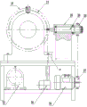
Fig. 1 is a front view of the present invention;
fig. 2 is a top view of the present invention;
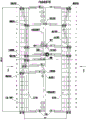
fig. 3 is a side view of the present invention;
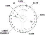
fig. 4 is a cam curve development view of the present invention;
FIG. 5 is the movement trace of the left cam control mandrel of the present invention;
fig. 6 shows the right cam controlling the movement track of the mandrel of the present invention.
Description of the parts: 1. the milling cutter comprises a support, 2, a left cam, 3, a slide rail seat, 4, a mandrel seat, 5, a mandrel, 6, a material receiving disc, 7, a flange sleeve, 81, a male die, 82, a female die, 9, a push-pull plate, 10, a right cam, 11, a spacer bush, 12, a main shaft, 13, a large chain wheel, 14, a retainer ring, 15, a baffle, 16, a cover removing disc, 17, an eccentric shaft, 18, a small chain wheel, 19, a cam driven bearing, 20, a linear slide rail pair, 21, a chip collecting hopper, 22, a milling cutter, 23, a speed reducing motor, 24, a high-speed motor, 25, a milling cutter main shaft support, 26, a milling cutter main shaft, 27, a chain wheel, 28, a chain wheel, 29, a rack 30 and a.
Detailed Description
For a better understanding and appreciation of the invention, it will be further described in connection with the accompanying drawings: a full-automatic aluminum cover top convex character raising and milling convex character integrated machine comprises a frame 29, a speed reducing motor 23 and a high-speed motor 24 are arranged below the frame 29, the speed reducing motor 23 is connected with a small chain wheel 18, a support 1 is fixedly arranged above the frame 29, a main shaft 12 is arranged in a central hole of the support 1, a left cam 2 and a right cam 10 are respectively arranged at two ends of the support 1, the left cam 2 and the right cam 10 are arranged on the main shaft 12 through a spacer 11, a large chain wheel 13 is arranged at the rightmost end of the main shaft 12, the large chain wheel 13 is connected with the small chain wheel 18 through a chain, slide rail seats 3 are respectively arranged at two ends of the main shaft 12, linear slide rail pairs 20 are arranged on the slide rail seats 3, a mandrel seat 4 is fixedly arranged on the linear slide rail pairs 20, a push-pull plate 9 is arranged on the mandrel seat 4, two cam driven bearings 19 are arranged at one end of the push-pull plate 9, the cam driven bearings 19 are respectively and tightly attached to, a female die 82 is arranged at the right end of the left mandrel 5, a male die 81 is arranged at the left end of the right mandrel, a retainer ring 14 is arranged at the rear end of the mandrel 5, and a material receiving disc 6 is fixedly arranged in the middle of the main shaft 12 through a flange sleeve 7; a milling cutter main shaft support 25 is further arranged on the rack 29, a milling cutter main shaft 26 is arranged in a central hole of the milling cutter main shaft support 25, a milling cutter 22 is arranged at one end of the milling cutter main shaft 26, the other end of the milling cutter main shaft 26 is connected with an upper chain wheel 28, the upper chain wheel 28 is connected with a chain wheel 27 on a high-speed motor 24 through a chain, the milling cutter main shaft 26 and the main shaft 12 are located on the same horizontal line, a stripping plate 16 is arranged on the inner side of the sliding rail seat 3, and; an eccentric shaft 17 is arranged on the push-pull plate 9, and the eccentric shaft 17 is positioned at the rear side of the mandrel seat 4; a scrap collecting hopper 21 is arranged above the frame 29 and below the material receiving tray 6, and the scrap collecting hopper 21 is connected with a dust suction device 30 arranged below the frame 29 through a dust suction pipeline.
Specifically, the reduction motor 23 drives the small chain wheel 18 to rotate and then drives the large chain wheel 13 to rotate, the large chain wheel 13 drives the main shaft 12 to rotate, the main shaft 12 drives the two slide rail seats 3 to rotate, the linear slide rail pairs 20 are arranged on the slide rail seats 3, the mandrel seat 4 is fixed on the linear guide rail pairs 20, the push-pull plate 9 is arranged on the mandrel seat 4, the other end of the push-pull plate 9 is provided with two cam driven bearings 19, and the two cam driven bearings 19 are tightly attached to the curved bosses of the left cam 2 and the right cam 10 (see fig. 3).
The slide rail seat 3 rotates to drive the push-pull plate 9 to move, and further drives the cam driven bearing 19 on the push-pull plate 9 to do longitudinal linear motion according to the curve track of the cam boss (see fig. 3).
The pattern on the top plane of the bottle cap can be extruded when the convex curves of the left cam 2 and the right cam 10 drive the push-pull plates 9 on both sides to press the male die and the female die on the mandrel 05 on both sides together (see figure 4).
The thickness of the top plane of the workpiece (aluminum bottle cap) is about 0.2 mm, and the extrusion depth of each pair of male die and female die can be adjusted by adjusting the eccentric amount of the cam driven bearing 19.
The function of the eccentric shaft 17 is to lock the mandrel base 4 and prevent the mandrel base 4 from moving backwards when the cam is pressed (see fig. 3).
The workpiece flows to the material receiving disc 6 through the slideway, and the material receiving disc 6 is arranged on the flange sleeve 7. When the main shaft 12 rotates to drive the material receiving disc 6 to rotate, a workpiece falls into the groove of the material receiving disc 6, and when the material receiving disc 6 rotates clockwise (see figure 4) to 0 point, the cam rolling bearing 19 on the boss of the left cam 2 is driven along the curve of the boss, so that the push-pull plate 9 drives the mandrel seat 4 to push the mandrel 5 into the workpiece hole, and the cover pushing action is started. Similarly, the right cam 10 drives the related components to start to move towards the center, when the take-up pan 6 rotates to 4 points, the left cam 2 and the right cam 10 simultaneously drive the related components to extrude the male die 81 and the female die 82 together to complete the raised characters (patterns), and then the related components continue to rotate to 5 points to complete the extrusion raised character formation.
And after the extrusion is finished, the extrusion process is operated to 9 points to begin character milling. The milled aluminum scraps fall into a scrap collecting hopper 21 below and are collected by a dust collection device 30. When related elements pass through 12 points along the linear boss of the left cam 2, the mandrel 5 retreats, the cover-removing action starts under the action of the blocking piece 15, the mandrel 5 stops retreating when the linear boss continues to reach 15 points, the cover-removing action is completely finished, and the blocking piece 15 is installed on the cover-removing plate 16 and plays a role in cover-removing.
The capping (feeding) was started when the run reached 22 o' clock. At the same time, the right cam 10 drives the relevant element to go back after 5 points. When 9 o 'clock, the backward movement is completed to make room for the milling cutter 22 to mill characters (see fig. 2), and when 9 o' clock, the milling cutter 22 completes the character milling process, the milling cutter 22 is installed on the milling cutter spindle 26, the high-speed motor 24 drives the upper chain wheel 28 to rotate through the chain wheel 27 installed at the shaft end, and then drives the milling cutter spindle 26 to make the milling cutter 22 rotate at high speed. The right cam 10 repeats the above actions when running to the 0 point.
The utility model discloses collect protruding word process and mill two units of word process and close as an organic wholely, simplified equipment structure and made equipment compacter, the punching press action that will dash the top word changes into and does not have the impact action, adopts the extrusion motion shaping that utilizes cam curvilinear motion orbit to form. The punching noise is eliminated, the stability of the equipment is improved, and the service life of the equipment is prolonged. The intermittent motion of the original production process is changed into continuous non-intermittent motion, and the production efficiency is stabilized to more than 200 pieces per minute.
After the convex character working procedure and the convex character milling working procedure are combined into an integrated machine, the working procedure is transferred after convex character raising to save a separator and a feeding slideway in the convex character milling process, the pollution to workpieces in the process of queuing and feeding again is reduced, the waste products generated by collision and extrusion in the sorting process of the separator in secondary queuing and feeding are reduced, and the occupied area of equipment is also reduced.
Claims (3)
1. A full-automatic aluminum cover top raising and milling convex character integrated machine comprises a rack (29), wherein a speed reducing motor (23) and a high-speed motor (24) are arranged below the rack (29), the speed reducing motor (23) is connected with a small chain wheel (18), and the full-automatic aluminum cover top raising and milling convex character integrated machine is characterized in that a support (1) is fixedly arranged above the rack (29), a main shaft (12) is arranged in a central hole of the support (1), a left cam (2) and a right cam (10) are respectively arranged at two ends of the support (1), the left cam (2) and the right cam (10) are arranged on the main shaft (12) through a spacer bush (11), a large chain wheel (13) is arranged at the rightmost end of the main shaft (12), the large chain wheel (13) is connected with the small chain wheel (18) through a chain, slide rail seats (3) are respectively arranged at two ends of the main shaft (12), a linear slide rail pair (20) is arranged on the slide rail, a push-pull plate (9) is arranged on the mandrel seat (4), two cam driven bearings (19) are arranged at one end of the push-pull plate (9), the cam driven bearings (19) are tightly attached to curve bosses of the left cam (2) and the right cam (10) respectively, a mandrel (5) is arranged in a central hole of the mandrel seat (4), a female die (82) is arranged at the right end of the mandrel at the left side, a male die (81) is arranged at the left end of the mandrel at the right side, a check ring (14) is arranged at the rear end of the mandrel (5), and a material receiving disc (6) is fixedly arranged in the middle of the main shaft (12) through a flange; still be equipped with milling cutter main shaft support (25) on frame (29), be equipped with milling cutter main shaft (26) in milling cutter main shaft support (25) the centre bore, milling cutter main shaft (26) one end is equipped with milling cutter (22), and milling cutter main shaft (26) other end links to each other with last sprocket (28), goes up sprocket (28) and links to each other through sprocket (27) on chain and high-speed motor (24), and milling cutter main shaft (26) are located same water flat line with main shaft (12), and slide rail seat (3) inboard is equipped with and takes off apron (16), be equipped with separation blade (15) on taking off apron (16).
2. The full-automatic aluminum cover top raising and milling integrated machine according to claim 1, wherein the push-pull plate (9) is provided with an eccentric shaft (17), and the eccentric shaft (17) is positioned at the rear side of the mandrel seat (4).
3. The full-automatic aluminum cover top raised letter milling raised letter all-in-one machine as claimed in claim 1, characterized in that a scrap collecting hopper (21) is arranged above the frame (29) and below the receiving tray (6), and the scrap collecting hopper (21) is connected with a dust suction device (30) arranged below the frame (29) through a dust suction pipeline.
Priority Applications (1)
| Application Number | Priority Date | Filing Date | Title |
|---|---|---|---|
| CN202020897269.5U CN212265140U (en) | 2020-05-26 | 2020-05-26 | Full-automatic aluminum cover top convex character milling and milling integrated machine |
Applications Claiming Priority (1)
| Application Number | Priority Date | Filing Date | Title |
|---|---|---|---|
| CN202020897269.5U CN212265140U (en) | 2020-05-26 | 2020-05-26 | Full-automatic aluminum cover top convex character milling and milling integrated machine |
Publications (1)
| Publication Number | Publication Date |
|---|---|
| CN212265140U true CN212265140U (en) | 2021-01-01 |
Family
ID=73881009
Family Applications (1)
| Application Number | Title | Priority Date | Filing Date |
|---|---|---|---|
| CN202020897269.5U Active CN212265140U (en) | 2020-05-26 | 2020-05-26 | Full-automatic aluminum cover top convex character milling and milling integrated machine |
Country Status (1)
| Country | Link |
|---|---|
| CN (1) | CN212265140U (en) |
-
2020
- 2020-05-26 CN CN202020897269.5U patent/CN212265140U/en active Active
Similar Documents
| Publication | Publication Date | Title |
|---|---|---|
| CN215143862U (en) | Stamping die is used in processing | |
| CN211965671U (en) | Automatic blanking machine of stamping device | |
| CN113458258A (en) | Efficient aluminum alloy sheet stamping die and stamping method thereof | |
| CN1665597A (en) | Shredding machines | |
| CN106111775A (en) | Special smoothing press | |
| CN212265140U (en) | Full-automatic aluminum cover top convex character milling and milling integrated machine | |
| CN101758101A (en) | High-precision electrode extrusion forming hydrostatic press | |
| CN101979175A (en) | High-speed automatic punching machine and working mode thereof | |
| CN112743618A (en) | Die-cutting machine with waste cleaning device | |
| CN111571228A (en) | Full-automatic aluminum cover top convex character milling and milling integrated machine | |
| CN201333723Y (en) | Rolling type punching machine | |
| CN202087684U (en) | Novel penetrating type side piercing die | |
| CN217252296U (en) | Punching machine with continuous stamping die | |
| CN217095386U (en) | Stamping lathe for machine manufacturing | |
| CN2279994Y (en) | Round pressing, round cutting device | |
| CN203470714U (en) | Automatic feeding mechanism for blanking | |
| CN212704636U (en) | Plate shearing device of metal plate stamping and shearing equipment | |
| CN206083628U (en) | Mandrel side of floating there is curved mould of ejection type edge rolling | |
| CN214556647U (en) | Punching device for front hub production | |
| CN201997589U (en) | A high-speed automatic punching machine | |
| CN212598205U (en) | Multistation formula stamping die is used in automobile parts processing | |
| CN2053951U (en) | Automatic feeding device for die stamping of stamping machine | |
| CN111872225A (en) | Panel punching equipment | |
| CN220028346U (en) | Chain plate stamping forming device | |
| CN211990483U (en) | Supplementary piece piercing press of getting based on structure of kick-backing |
Legal Events
| Date | Code | Title | Description |
|---|---|---|---|
| GR01 | Patent grant | ||
| GR01 | Patent grant |