CN212259625U - A high-efficient heat dissipation rack for computer lab - Google Patents
A high-efficient heat dissipation rack for computer lab Download PDFInfo
- Publication number
- CN212259625U CN212259625U CN202020828204.5U CN202020828204U CN212259625U CN 212259625 U CN212259625 U CN 212259625U CN 202020828204 U CN202020828204 U CN 202020828204U CN 212259625 U CN212259625 U CN 212259625U
- Authority
- CN
- China
- Prior art keywords
- heat dissipation
- cabinet body
- cabinet
- box
- plate
- Prior art date
- Legal status (The legal status is an assumption and is not a legal conclusion. Google has not performed a legal analysis and makes no representation as to the accuracy of the status listed.)
- Active
Links
Images


Abstract
The utility model discloses a high-efficiency heat dissipation cabinet for a machine room, which comprises a cabinet body, wherein one end of the cabinet body is provided with a plurality of ventilation windows, a placing pore plate is connected between the middle parts of the inner walls at the two sides of the cabinet body, a mesh plate is arranged on the lower inner wall of the cabinet body, one end of the cabinet body is movably connected with a cover plate, one end of the cover plate is provided with an observation window, the other end of the cabinet body is fixedly connected with a condensing device, the lower end of the cabinet body is connected with a movable heat dissipation device, the upper end of the cabinet body is provided with an air draft dust prevention device, the utility model has simple and convenient operation, the universal wheel which can be assembled facilitates the movement of the cabinet by arranging the movable heat dissipation device, so that the cabinet can more flexibly adjust the working position, the flexibility of the whole cabinet is higher, and the condensing, the radiating speed is faster, and the practicality of the cabinet is improved.
Description
Technical Field
The utility model relates to a rack field specifically is a high-efficient heat dissipation rack for computer lab.
Background
The cabinet is an indispensable component in electrical equipment, is an independent or self-supporting casing for accommodating electrical or electronic equipment, is a carrier of electrical control equipment, is too simple in structure at present, is poor in heat dissipation effect, and only uses a single heat dissipation fan for heat dissipation, so that the electrical control equipment in the cabinet is easily damaged during long-time work, the service life of the electrical control equipment is shortened, and the practicability of the whole cabinet is also reduced.
SUMMERY OF THE UTILITY MODEL
An object of the utility model is to provide a high-efficient heat dissipation rack for computer lab to solve the problem that proposes among the above-mentioned background art.
In order to achieve the above object, the utility model provides a following technical scheme: a high-efficiency heat dissipation cabinet for a machine room comprises a cabinet body, wherein a plurality of ventilation windows are arranged at one end of the cabinet body, a placing pore plate is connected between the middle parts of the inner walls of two sides of the cabinet body, a mesh plate is arranged on the lower inner wall of the cabinet body, one end of the cabinet body is movably connected with a cover plate, an observation window is arranged at one end of the cover plate, the other end of the cabinet body is fixedly connected with a condensing device, and a movable heat dissipation device is connected with the lower end of the;
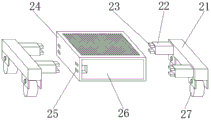
the movable heat dissipation device comprises two long rods and a heat dissipation box, universal wheels are arranged on two sides of the lower ends of the two long rods, connecting rods are arranged on two sides of one end of each long rod, a plywood is movably connected to the front end of the heat dissipation box, a supporting plate is connected between the inner walls of two sides of the heat dissipation box, a hydraulic cylinder is connected to the lower end of the supporting plate, a hydraulic rod is connected to the lower end of the hydraulic cylinder in a transmission mode, and a supporting frame is arranged at the lower end of the hydraulic;
convulsions dust keeper is installed to cabinet body upper end, convulsions dust keeper includes the carriage, the top of carriage is provided with the cornice, the top of cornice is connected with the dust screen.
As a preferred technical scheme of the utility model, the one end that the stock was kept away from to the connecting rod is connected with two buckles, the draw-in groove that uses with the buckle cooperation has all been opened at the both ends of heat dissipation case.
As a preferred technical scheme of the utility model, the top fixedly connected with cooling fan of backup pad, open on the top of heat dissipation case has the air-out net, and the lower extreme of heat dissipation case is opened has the through-hole that two cooperation support frames used.
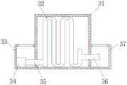
As a preferred technical scheme of the utility model, condensing equipment includes the box, and the box is in the same place with the one end fixed connection of the cabinet body, the one end of box is connected with the other end of case and box of intaking and is connected with the drain tank, be provided with the condensate pipe in the box, install the water pump in the case of intaking, the one end of water pump is connected with the inlet tube, and the one end that the water pump was kept away from to the inlet tube is linked together with the condensate pipe, the one end of condensate pipe is connected with the drain pipe, and the drain pipe one end of keeping away from the condensate pipe runs through the drain tank and.
As a preferred technical scheme of the utility model, fixedly connected with fixed plate between the both sides inner wall of connecting frame, the lower extreme of fixed plate is provided with the air exhauster, the top of air exhauster is connected with the blast pipe, and the top of blast pipe runs through the fixed plate.
As an optimized technical scheme of the utility model, the position of air-out net is corresponding with the position of otter board.
Compared with the prior art, the beneficial effects of the utility model are that:
1. the utility model discloses a set up condensing equipment, condensate pipe wherein can dispel the heat to this rack to use by the air exhauster among the cooling fan cooperation convulsions dust keeper, can make the radiating mode of this rack more diversified, can carry out the high efficiency's heat dissipation to the electrical control equipment in this rack, be favorable to improving electrical control equipment's life and the practicality of this rack.
2. Through setting up the removal heat abstractor, pneumatic cylinder wherein can make the hydraulic stem drive the support frame and prop up this cabinet body to make the universal wheel can assemble together with the heat dissipation case, make this rack can carry out more convenient removal, improved the flexibility of this rack.
Drawings
FIG. 1 is a schematic structural view of the present invention;
fig. 2 is a schematic view of the mobile heat dissipation device of the present invention;
FIG. 3 is a cross-sectional view of the heat dissipation case of the present invention;
FIG. 4 is a cross-sectional view of the condensing unit of the present invention;
fig. 5 is the utility model discloses convulsions dust keeper sketch map and connection frame sectional view.
In the figure: 1. a cabinet body; 2. a mobile heat sink; 3. a condensing unit; 4. an air draft dustproof device; 5. a screen plate; 6. placing a pore plate; 7. an observation window; 8. a cover plate; 9. a ventilation window; 21. a long rod; 22. a connecting rod; 23. buckling; 24. a heat dissipation box; 25. a card slot; 26. plywood; 27. a universal wheel; 31. a box body; 32. a condensate pipe; 33. a water inlet tank; 34. a water pump; 35. a water inlet pipe; 36. a drain pipe; 37. a drain tank; 41. a connecting frame; 42. a fascia; 43. a dust screen; 44. a fixing plate; 45. an exhaust fan; 46. An exhaust pipe; 241. a hydraulic cylinder; 242. a through hole; 243. a support frame; 244. a support plate; 245. a heat radiation fan; 246. an air outlet net; 247. a hydraulic rod.
Detailed Description
The technical solutions in the embodiments of the present invention will be described clearly and completely with reference to the accompanying drawings in the embodiments of the present invention, and it is obvious that the described embodiments are only some embodiments of the present invention, not all embodiments. Based on the embodiments in the present invention, all other embodiments obtained by a person skilled in the art without creative work belong to the protection scope of the present invention.
Referring to fig. 1-5, the present invention provides a technical solution: a high-efficiency heat dissipation cabinet for a machine room comprises a cabinet body 1, wherein one end of the cabinet body 1 is provided with a plurality of ventilation windows 9, a placing pore plate 6 is connected between the middle parts of the inner walls of the two sides of the cabinet body 1, a mesh plate 5 is installed on the lower inner wall of the cabinet body 1, one end of the cabinet body 1 is movably connected with a cover plate 8, one end of the cover plate 8 is provided with an observation window 7, when in use, the cover plate 8 is firstly opened to place electrical control equipment on the placing pore plate 6 and the mesh plate 5, the observation window 7 on the cover plate 8 can facilitate workers to observe the working condition of the electrical control equipment, the other end of the cabinet body 1 is fixedly connected with a condensing device 3, the lower end of the cabinet body 1 is connected with a movable heat dissipation device 2, the movable heat dissipation device 2 comprises a long rod 21 and a heat dissipation box 24, the long rod, 24 front end swing joint of heat dissipation case has plywood 26, is connected with backup pad 244 between the both sides inner wall of heat dissipation case 24, and backup pad 244 lower extreme is connected with pneumatic cylinder 241, and pneumatic cylinder 241 lower extreme transmission is connected with hydraulic stem 247, and support frame 243 is installed to hydraulic stem 247 lower extreme, and convulsions dust keeper 4 is installed to cabinet body 1 upper end, and convulsions dust keeper 4 includes carriage 41, and the top of carriage 41 is provided with cornice 42, and the top of cornice 42 is connected with dust screen 43.
Referring to fig. 1-5, one end of the connecting rod 22 away from the long rod 21 is connected with two buckles 23, two ends of the heat dissipation box 24 are respectively provided with a clamping groove 25 matched with the buckles 23, when the cabinet needs to be moved, the plywood 26 on the heat dissipation box 24 can be opened first to start the hydraulic cylinder 241 in the heat dissipation box 24, so that the hydraulic rod 247 drives the support frame 243 to pass through the through hole 242 to support the whole cabinet, then the two long rods 21 are clamped into the clamping grooves 25 on the heat dissipation box 24 through the buckles 23 on the connecting rod 22 to complete the assembly of the universal wheels 27, and then the support frame 243 is retracted through the hydraulic cylinder 241, at this time, the cabinet can be moved.
Referring to fig. 1-5, a heat dissipation fan 245 is fixedly connected to the top end of the supporting plate 244, an air outlet net 246 is disposed on the top end of the heat dissipation box 24, two through holes 242 matched with the supporting frame 243 are disposed on the lower end of the heat dissipation box 24, when heat dissipation is performed, the heat dissipation fan 245 in the heat dissipation box 24 can be started to blow air towards the air outlet net 246, and the air blown out by the heat dissipation fan 245 can enter the cabinet 1 through the screen 5.
Referring to fig. 1-5, the condensing unit 3 includes a box 31, the box 31 is fixedly connected to one end of the cabinet 1, one end of the box 31 is connected to a water inlet tank 33, the other end of the box 31 is connected to a water outlet tank 37, a condensed water pipe 32 is disposed in the box 31, a water pump 34 is disposed in the water inlet tank 33, one end of the water pump 34 is connected to a water inlet pipe 35, one end of the water inlet pipe 35, which is far away from the water pump 34, is communicated with the condensed water pipe 32, one end of the condensed water pipe 32 is connected to a water outlet pipe 36, and one end of the water outlet pipe 36, which is far away from the condensed water pipe 32, penetrates through the water outlet tank 37 and extends into the water outlet tank 37, when the condensing unit 3 is required to operate, cold water can be added into the water inlet tank 33, the water pump 34 in the water inlet, and the water having absorbed heat in the condensate pipe 32 is introduced into the drain tank 37 through the drain pipe 36.
Referring to fig. 1-5, a fixing plate 44 is fixedly connected between the inner walls of the two sides of the connecting frame 41, a suction fan 45 is disposed at the lower end of the fixing plate 44, an exhaust pipe 46 is connected to the top end of the suction fan 45, and the top end of the exhaust pipe 46 penetrates through the fixing plate 44, when the heat dissipation fan 245 is started, the suction fan 45 in the connecting frame 41 is started to be used in cooperation with the heat dissipation fan 245, so that heat is quickly drawn out of the cabinet body 1 through the exhaust pipe 46, and the cornice 42 and the dust screen 43 mounted at the top end of the connecting frame 41 can protect the electrical control devices in the cabinet body 1 from dust.
Referring to fig. 1-5, the position of the air outlet net 246 corresponds to the position of the net plate 5, so that the heat dissipation effect of the heat dissipation fan 245 is better.
The working principle is as follows: when the cabinet is used, firstly the cover plate 8 is opened to place the electric control equipment on the placing pore plate 6 and the mesh plate 5, the observation window 7 on the cover plate 8 can be convenient for workers to observe the working condition of the electric control equipment, when the cabinet needs to be moved, the plywood 26 on the heat dissipation box 24 can be firstly opened to start the hydraulic cylinder 241 in the heat dissipation box 24, the hydraulic rod 247 drives the support frame 243 to penetrate through the through hole 242 to support the whole cabinet, then the two long rods 21 are clamped into the clamping groove 25 on the heat dissipation box 24 through the clamping buckles 23 on the connecting rods 22 to complete the assembly of the universal wheels 27, then the support frame 243 is folded through the hydraulic cylinder 241, at the moment, the cabinet can be moved, when the condensing device 3 needs to work, cold water can be added into the water inlet box 33, then the water pump 34 in the water inlet box 33 is started to enable the water inlet pipe 35 to start to supply water into the, at this moment, the condensate pipe 32 will absorb the heat in the cabinet 1, and the water absorbed heat in the condensate pipe 32 will enter the drain tank 37 through the drain pipe 36, and when the condensing device 3 is cooperated to perform efficient and rapid heat dissipation, the heat dissipation fan 245 in the heat dissipation box 24 can be started to blow air towards the air outlet net 246, the air blown out by the heat dissipation fan 245 will enter the cabinet 1 through the net plate 5, and when the heat dissipation fan 245 is started, the exhaust fan 45 in the connection frame 41 is started to be cooperated with the heat dissipation fan 245 for use, so that the heat is rapidly drawn out of the cabinet 1 through the exhaust pipe 46, and the cornice plate 42 and the dust screen 43 installed at the top end of the connection frame 41 can perform dust protection on the electric control equipment in the cabinet 1.
Although embodiments of the present invention have been shown and described, it will be appreciated by those skilled in the art that changes, modifications, substitutions and alterations can be made in these embodiments without departing from the principles and spirit of the invention, the scope of which is defined in the appended claims and their equivalents.
Claims (6)
1. The utility model provides a high-efficient heat dissipation rack for computer lab, includes the cabinet body (1), its characterized in that: a plurality of ventilation windows (9) are arranged at one end of the cabinet body (1), a placing pore plate (6) is connected between the middle parts of the inner walls at two sides of the cabinet body (1), a mesh plate (5) is installed on the lower inner wall of the cabinet body (1), one end of the cabinet body (1) is movably connected with a cover plate (8), one end of the cover plate (8) is provided with an observation window (7), the other end of the cabinet body (1) is fixedly connected with a condensing device (3), and the lower end of the cabinet body (1) is connected with a movable heat dissipation device (2);
the movable heat dissipation device (2) comprises long rods (21) and heat dissipation boxes (24), the number of the long rods (21) is two, universal wheels (27) are arranged on two sides of the lower ends of the two long rods (21), connecting rods (22) are arranged on two sides of one end of each long rod (21), a plywood (26) is movably connected to the front end of each heat dissipation box (24), a supporting plate (244) is connected between the inner walls of two sides of each heat dissipation box (24), a hydraulic cylinder (241) is connected to the lower end of each supporting plate (244), a hydraulic rod (247) is connected to the lower end of each hydraulic cylinder (241) in a transmission mode, and a supporting frame (243) is installed at;
convulsions dust keeper (4) are installed to cabinet body (1) upper end, convulsions dust keeper (4) are including connection frame (41), the top of connection frame (41) is provided with cornice (42), the top of cornice (42) is connected with dust screen (43).
2. The cabinet with high heat dissipation efficiency for the machine room of claim 1, wherein: the one end that stock (21) was kept away from in connecting rod (22) is connected with two buckles (23), draw-in groove (25) that use with buckle (23) cooperation have all been opened at the both ends of heat dissipation case (24).
3. The cabinet with high heat dissipation efficiency for the machine room of claim 1, wherein: the top fixedly connected with radiator fan (245) of backup pad (244), open the top of heat dissipation case (24) has air-out net (246), and the lower extreme of heat dissipation case (24) is opened has through-hole (242) that two cooperation support frames (243) used.
4. The cabinet with high heat dissipation efficiency for the machine room of claim 1, wherein: condensing equipment (3) include box (31), and box (31) and the one end fixed connection of the cabinet body (1) are in the same place, the one end of box (31) is connected with the other end of intaking case (33) and box (31) and is connected with drain box (37), be provided with condenser pipe (32) in box (31), install water pump (34) in intaking case (33), the one end of water pump (34) is connected with inlet tube (35), and inlet tube (35) keep away from the one end of water pump (34) and be linked together with condenser pipe (32), the one end of condenser pipe (32) is connected with drain pipe (36), and drain pipe (36) keep away from the one end of condenser pipe (32) and run through drain box (37) and extend to inside drain box (37).
5. The cabinet with high heat dissipation efficiency for the machine room of claim 1, wherein: fixed plate (44) is fixedly connected between the both sides inner wall of connecting frame (41), the lower extreme of fixed plate (44) is provided with air exhauster (45), the top of air exhauster (45) is connected with blast pipe (46), and fixed plate (44) is run through on the top of blast pipe (46).
6. The cabinet with high heat dissipation efficiency for the machine room of claim 3, wherein: the position of the air outlet net (246) corresponds to the position of the screen plate (5).
Priority Applications (1)
| Application Number | Priority Date | Filing Date | Title |
|---|---|---|---|
| CN202020828204.5U CN212259625U (en) | 2020-05-18 | 2020-05-18 | A high-efficient heat dissipation rack for computer lab |
Applications Claiming Priority (1)
| Application Number | Priority Date | Filing Date | Title |
|---|---|---|---|
| CN202020828204.5U CN212259625U (en) | 2020-05-18 | 2020-05-18 | A high-efficient heat dissipation rack for computer lab |
Publications (1)
| Publication Number | Publication Date |
|---|---|
| CN212259625U true CN212259625U (en) | 2020-12-29 |
Family
ID=74001096
Family Applications (1)
| Application Number | Title | Priority Date | Filing Date |
|---|---|---|---|
| CN202020828204.5U Active CN212259625U (en) | 2020-05-18 | 2020-05-18 | A high-efficient heat dissipation rack for computer lab |
Country Status (1)
| Country | Link |
|---|---|
| CN (1) | CN212259625U (en) |
Cited By (2)
| Publication number | Priority date | Publication date | Assignee | Title |
|---|---|---|---|---|
| CN113001568A (en) * | 2021-02-26 | 2021-06-22 | 杭州临润贸易有限公司 | Industrial robot is with switch board that has dampproofing function of cooling |
| CN113225986A (en) * | 2021-04-13 | 2021-08-06 | 吕芹 | High-efficient heat dissipation equipment supporting component in computer lab |
-
2020
- 2020-05-18 CN CN202020828204.5U patent/CN212259625U/en active Active
Cited By (3)
| Publication number | Priority date | Publication date | Assignee | Title |
|---|---|---|---|---|
| CN113001568A (en) * | 2021-02-26 | 2021-06-22 | 杭州临润贸易有限公司 | Industrial robot is with switch board that has dampproofing function of cooling |
| CN113001568B (en) * | 2021-02-26 | 2022-08-30 | 重庆博森电气(集团)有限公司 | Industrial robot is with switch board that has dampproofing function of cooling |
| CN113225986A (en) * | 2021-04-13 | 2021-08-06 | 吕芹 | High-efficient heat dissipation equipment supporting component in computer lab |
Similar Documents
| Publication | Publication Date | Title |
|---|---|---|
| CN212259625U (en) | A high-efficient heat dissipation rack for computer lab | |
| CN115633269B (en) | Environment-friendly energy-saving type network switch cabinet | |
| CN111459256A (en) | Convection type computer host heat dissipation device | |
| CN218449074U (en) | Switch board with protective structure | |
| CN211906190U (en) | Safety application device for computer informatization | |
| CN211790115U (en) | Switch board with heat dissipation dust removal function | |
| CN210808044U (en) | Cooling device for communication power supply equipment | |
| CN212437882U (en) | Low-voltage inverter accomodates cabinet convenient to installation is maintained | |
| CN111049041A (en) | Ventilation device for electric power metering cabinet and use method thereof | |
| CN220358586U (en) | Dampproofing electric capacity compensation cabinet dispels heat | |
| CN220545370U (en) | High-efficient heat dissipation rack | |
| CN213662274U (en) | Heat dissipation system for outer box of platform base station and outer box of platform base station | |
| CN115864187A (en) | Cooling equipment and method for box-type substation | |
| CN211625504U (en) | Energy-saving air conditioner water cooling unit | |
| CN215934193U (en) | Embedded distribution switch control box convenient to use | |
| CN212413657U (en) | Intelligent traffic monitoring case | |
| CN220680198U (en) | Sheet metal outer cover of numerical control machine tool | |
| CN210291171U (en) | Can high-efficient radiating multi-functional gas chromatograph place rack | |
| CN212619579U (en) | Electric pulse spark machine coolant liquid circulating filter device | |
| CN218006852U (en) | Electrical equipment management device with good heat dissipation effect | |
| CN219513700U (en) | High-efficient heat dissipation formula cable branch case | |
| CN216672839U (en) | Frequency converter driving device | |
| CN212968628U (en) | Wind-cooled switch cabinet of wind generating set | |
| CN218449120U (en) | Ventilation structure and electric power cabinet thereof | |
| CN218788604U (en) | Strong electricity isolation device of power output management system |
Legal Events
| Date | Code | Title | Description |
|---|---|---|---|
| GR01 | Patent grant | ||
| GR01 | Patent grant |