CN212251393U - Hoist type hoist - Google Patents
Hoist type hoist Download PDFInfo
- Publication number
- CN212251393U CN212251393U CN202020858500.XU CN202020858500U CN212251393U CN 212251393 U CN212251393 U CN 212251393U CN 202020858500 U CN202020858500 U CN 202020858500U CN 212251393 U CN212251393 U CN 212251393U
- Authority
- CN
- China
- Prior art keywords
- speed reducer
- hoist
- motor
- drum
- hoisting
- Prior art date
- Legal status (The legal status is an assumption and is not a legal conclusion. Google has not performed a legal analysis and makes no representation as to the accuracy of the status listed.)
- Active
Links
Images



Landscapes
- Connection Of Motors, Electrical Generators, Mechanical Devices, And The Like (AREA)
Abstract
The application provides a hoist formula headstock gear relates to water conservancy hydroelectric mechanical equipment field. The hoisting hoist comprises a frame, a synchronous connecting shaft and two hoisting point assemblies arranged on the frame at intervals, wherein the two hoisting point assemblies are connected through the synchronous connecting shaft. Each lifting point component comprises a motor, a speed reducer, a torsion arm and a lifting mechanism for lifting; the motor is arranged on the frame. The lifting mechanism includes a drum. The power input shaft of the speed reducer is connected with the motor, the power output shaft of the speed reducer is connected with the winding drum, the speed reducer is supported above the rack through a torsion arm, and the torsion arm is located right below the power input shaft of the speed reducer. The motor is used for driving the winding drum to rotate through the speed reducer so as to enable the lifting mechanism to lift. The speed reducer is supported above the rack through the torque arm, the torque arm is arranged right below a power input shaft of the speed reducer, the speed reducer only bears rotary load due to the arrangement of the torque arm, the transmission of the winch hoist can be more stable, and the hoisting is safer.
Description
Technical Field
The application relates to the field of water conservancy and hydropower mechanical equipment, in particular to a winch hoist.
Background
At present, a motor drives a winding drum to rotate through a speed reducer, a steel wire rope lifts a gate, and the requirement of opening and closing operation is met. The reducer is subjected to various loads such as radial load, vertical load, rotational load, impact load, and the like.
SUMMERY OF THE UTILITY MODEL
The embodiment of the application provides a winch hoist to improve the problem that the stress of a speed reducer of the conventional winch hoist is complex in the operation process.
The embodiment of the application provides a hoist formula headstock gear, including frame, synchronous connecting axle and interval arrangement two hoisting point subassemblies in the frame, two hoisting point subassemblies pass through the synchronous connecting axle and connect. Each lifting point component comprises a motor, a speed reducer, a torsion arm and a lifting mechanism for lifting; the motor is arranged on the frame. The lifting mechanism includes a drum. The power input shaft of the speed reducer is connected with the motor, the power output shaft of the speed reducer is connected with the winding drum, the speed reducer is supported above the rack through a torsion arm, and the torsion arm is located right below the power input shaft of the speed reducer. The motor is used for driving the winding drum to rotate through the speed reducer so as to enable the lifting mechanism to lift.
In the above technical solution, generally, during the operation of the speed reducer of the hoist, especially, the power input shaft of the speed reducer will bear various loads such as radial load, vertical load, rotational load, and impact load, the speed reducer is supported above the frame by the torque arm, and the torque arm is disposed right below the power input shaft of the speed reducer, so that the radial load, the vertical load, and the impact load borne by the speed reducer are borne by the drum long axis bearing block and the torque arm, that is, the drum long axis bearing block and the torque arm can bear and release the radial load, the vertical load, and the impact load borne by the speed reducer, and the speed reducer only bears the rotational load, so that the drive of the hoist can be more stable, and the hoist can be more stable and safer. The service life of the speed reducer can be prolonged, the failure rate of the whole winch hoist is reduced, and the total cost is reduced. And the two hoisting point assemblies are connected through the synchronous connecting shaft, so that the synchronous working transmission efficiency of the winch hoist is met.
In addition, the hoist of this application embodiment still has following additional technical characterstic:
in some embodiments of the present application, the torque arm is removably connected to the speed reducer; and/or the torsion arm is detachably connected with the frame.
Among the above-mentioned technical scheme, the torque arm can be dismantled with the reduction gear and be connected the installation of the reduction gear of being convenient for and dismantle, the maintenance of the reduction gear of being convenient for simultaneously. Because the torque arm bears more complicated load and needs frequent maintenance, the torque arm is detachably connected with the machine frame, and the maintenance of the torque arm is convenient.
In some embodiments of the present application, the speed reducer is connected to the torsion arm by a pin or bolt.
Among the above-mentioned technical scheme, the reduction gear passes through the bolt with the torque arm and realizes dismantling the connection, and its connected mode is simple, dismantles, the cost of installation and maintenance is low.
In some embodiments of the present application, one end of the synchronous connecting shaft is connected with the power input shaft of the speed reducer in one of the hoisting point assemblies, and the other end of the synchronous connecting shaft is connected with the power input shaft of the speed reducer in the other hoisting point assembly.
Among the above-mentioned technical scheme, the setting of synchronous connecting axle is convenient for realize the synchronous drive of two hoisting point subassemblies to the both ends of synchronous connecting axle are connected with the power input shaft of reduction gear respectively, and under the condition that does not influence starting efficiency, the power input shaft of reduction gear is low relative power output shaft's moment of torsion, can effectively reduce the manufacturing cost and the purchase cost of synchronous connecting axle.
In some embodiments of the present application, the lifting mechanism further comprises a pulley assembly comprising a fixed pulley; the winding drum is positioned above the frame, and the fixed pulley is rotatably connected to the frame and positioned above the frame.
Among the above-mentioned technical scheme, reel and fixed pulley are all with the top of frame, are convenient for reel and fixed pulley's maintenance.
In some embodiments of the present application, the frame includes a first supporting portion and a second supporting portion, and both ends of the winding drum are respectively rotatably supported by the first supporting portion and the second supporting portion.
Among the above-mentioned technical scheme, first supporting part and second supporting part rotate the both ends that support the reel, and when needs were overhauld the reduction gear, after reduction gear and reel were dismantled, the reel still can be supported by the frame, need not all dismantle with the reduction gear together with reel, hoist mechanism etc. the maintenance of the reduction gear of being convenient for can also reduce maintainer's work load.
In some embodiments of the present application, the hoist further includes a motor brake for releasing or braking the motor.
Among the above-mentioned technical scheme, motor brake's setting can be in time brakied the motor when any parts such as hoist mechanism, reduction gear break down, guarantees the safety of heavy objects such as gate and hoist formula headstock gear.
In some embodiments of the present application, the hoist further includes a drum brake mounted to the frame, the drum brake being used to release or brake the drum.
Among the above-mentioned technical scheme, the setting of reel stopper can in time stop the reel when any part such as hoist mechanism, reduction gear breaks down, avoids the reel to rotate under the action of gravity of heavy object and release the heavy object and injure the people below the heavy object by a crashing object, guarantees personnel, heavy objects such as gate and the safety of hoist formula headstock gear.
In some embodiments of the present application, the hoist further comprises a height limiter for limiting a hoisting height of the hoisting mechanism, and a load limiter disposed at an end of the drum away from the speed reducer; the load limiter is used for limiting the hoisting load of the lifting mechanism and is arranged at one end, far away from the speed reducer, of the winding drum.
Among the above-mentioned technical scheme, height limiter can guarantee that hoist formula headstock gear lifts by crane to suitable height, avoids excessively promoting or descend the heavy object, and load limiter can guarantee that hoist formula headstock gear jack-up weight is suitable, avoids the heavy object weight too big and damage hoist mechanism and avoids causing the incident among the jack-up process.
In some embodiments of the present application, the hoist further includes a connecting shaft support for supporting the synchronizing connecting shaft such that the synchronizing connecting shaft is coaxially arranged with the output shaft of the motor.
Among the above-mentioned technical scheme, the setting of connecting axle support can avoid appearing the condition of synchronous connecting axle decentraction and unstability because of synchronous connecting axle length is too big for synchronous transmission shaft can be better guarantee two reel synchronous rotations of hoisting point subassembly.
Drawings
In order to more clearly illustrate the technical solutions of the embodiments of the present application, the drawings that are required to be used in the embodiments will be briefly described below, it should be understood that the following drawings only illustrate some embodiments of the present application and therefore should not be considered as limiting the scope, and for those skilled in the art, other related drawings can be obtained from the drawings without inventive effort.
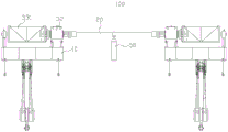
Fig. 1 is a schematic view of a first view angle of a hoist according to an embodiment of the present disclosure;
FIG. 2 is a schematic view of a first perspective of a hoist of the prior art;
FIG. 3 is an enlarged view at III of FIG. 1;
FIG. 4 is a schematic view of a second perspective of a hoist of the prior art;
fig. 5 is a schematic view of a second view angle of the hoist according to the embodiment of the present disclosure;
fig. 6 is a schematic view of a third view angle of the hoist according to the embodiment of the present disclosure.
Icon: 100-hoisting hoist; 10-a frame; 11-a third connection; 12-a fourth connection; 13-a first support; 14-a second support; 15-foundation bolts; 20-synchronous connecting shaft; 30-a lifting point assembly; 31-a motor; 32-a reducer; 321-a first connection; 322-a second connecting portion; 33-a lifting mechanism; 331-a reel; 332-a fixed pulley; 333-movable pulley; 334-steel wire ropes; 40-a torsion arm; 50-connecting shaft support; 60-a motor brake; 70-a drum brake; 80-a height limiter; 90-load limiter.
Detailed Description
In order to make the objects, technical solutions and advantages of the embodiments of the present application clearer, the technical solutions in the embodiments of the present application will be clearly and completely described below with reference to the drawings in the embodiments of the present application, and it is obvious that the described embodiments are some embodiments of the present application, but not all embodiments. The components of the embodiments of the present application, generally described and illustrated in the figures herein, can be arranged and designed in a wide variety of different configurations.
Thus, the following detailed description of the embodiments of the present application, presented in the accompanying drawings, is not intended to limit the scope of the claimed application, but is merely representative of selected embodiments of the application. All other embodiments, which can be derived by a person skilled in the art from the embodiments given herein without making any creative effort, shall fall within the protection scope of the present application.
It should be noted that the embodiments and features of the embodiments in the present application may be combined with each other without conflict.
It should be noted that: like reference numbers and letters refer to like items in the following figures, and thus, once an item is defined in one figure, it need not be further defined and explained in subsequent figures.
In the description of the embodiments of the present application, it should be noted that the indication of orientation or positional relationship is based on the orientation or positional relationship shown in the drawings, or the orientation or positional relationship which is usually placed when the product of the application is used, or the orientation or positional relationship which is usually understood by those skilled in the art, or the orientation or positional relationship which is usually placed when the product of the application is used, and is only for the convenience of describing the application and simplifying the description, but does not indicate or imply that the indicated device or element must have a specific orientation, be constructed in a specific orientation, and be operated, and thus, should not be construed as limiting the application. Furthermore, the terms "first," "second," "third," and the like are used solely to distinguish one from another and are not to be construed as indicating or implying relative importance.
Examples
As shown in fig. 1, an embodiment of the present application provides a hoist 100, where the hoist 100 includes a frame 10, a synchronous connecting shaft 20, and two hoisting point assemblies 30 arranged on the frame 10 at intervals, and the two hoisting point assemblies 30 are connected by the synchronous connecting shaft 20; each lifting point assembly 30 includes a motor 31, a reducer 32, a torsion arm 40, and a lifting mechanism 33 for lifting; the motor 31 is mounted to the frame 10. The lifting mechanism 33 comprises a winding drum 331, a power input shaft of the speed reducer 32 is connected with the motor 31, a power output shaft of the speed reducer 32 is connected with the winding drum 331, the speed reducer 32 is supported above the frame 10 through a torsion arm 40, and the torsion arm 40 is positioned right below the power input shaft of the speed reducer 32; the motor 31 is used to drive the drum 331 to rotate through the decelerator 32 to hoist the lifting mechanism 33.
The hoist 100 is a hoisting device that winds up a wire rope 334 or the like by a winding drum 331 of the hoisting mechanism 33 to hoist or lower a heavy object. The hoist 100 uses the motor 31 as a driving device, however, compared to the hoisting speed of the hoist 100, directly driving the winding drum 331 of the lifting mechanism 33 to rotate by the motor 31 to hoist the lifting mechanism 33 may cause the rotation speed of the winding drum 331 to be too fast, so that the hoisting speed of the lifting mechanism 33 is too fast, and the stability and safety of hoisting are reduced. Therefore, the decelerator 32 is provided between the motor 31 and the drum 331, and the motor 31 rotates the drum 331 through the decelerator 32, so that the rotation speed of the drum 331 is reduced relative to the rotation speed of the motor 31, and the lifting mechanism 33 can stably and safely lift the heavy object. In the prior art, as shown in fig. 2, when the motor 31, the winding drum 331 and the speed reducer 32 are arranged, generally, the bottom end of the speed reducer 32 is directly installed on the frame 10, the speed reducer 32 is directly connected with the winding drum 331 through a bearing, power output shafts of the speed reducers 32 of the two hoisting point assemblies 30 are connected through the synchronous connecting shaft 20, during the operation of the hoist type hoist 100, the winding drum 331 is driven by the motor 31 through the speed reducer 32 to rotate, and the hoisting mechanism 33 hoists a heavy object, so that the speed reducer 32 bears various loads such as a radial load, a vertical load, a rotational load, an impact load, and the.
In the present embodiment, the long axis of the winding drum 331 is connected to the power output shaft of the speed reducer 32 (the power output shaft of the speed reducer 32 is a hollow shaft) through a bearing seat, the motor 31 is connected to the power input shaft of the speed reducer 32, the speed reducer 32 is supported above the frame 10 through the torque arm 40, and the torque arm 40 is disposed right below the power input shaft of the speed reducer 32, so that the impact load borne by the speed reducer 32 is borne by the torque arm 40, that is, the torque arm 40 can release the impact load borne by the speed reducer 32; the bearing seat on the long axis side of the drum 331 receives the radial load and the vertical load of the speed reducer 32. The speed reducer 32 only bears the rotation load, so that the transmission of the hoist 100 is more stable, and the hoisting is more stable and safe. The load borne by the speed reducer 32 is reduced, the service life of the speed reducer 32 can be prolonged, the failure rate of the whole winch hoist 100 is reduced, and the total cost is reduced. And the two hoisting point assemblies 30 are connected by the synchronous connecting shaft 20 so that the working transmission efficiency of the hoist 100 is improved.
In the present embodiment, the torque arm 40 is detachably connected to the speed reducer 32; the torsion arm 40 is detachably connected to the frame 10. The torque arm 40 is detachably connected to the speed reducer 32 to facilitate the mounting and dismounting of the speed reducer 32 and also facilitate the maintenance of the speed reducer 32. Since the torsion arm 40 is subjected to complicated loads and requires frequent maintenance and replacement, the torsion arm 40 is detachably connected to the frame 10 to facilitate maintenance and replacement of the torsion arm 40. In other embodiments, one of the speed reducer 32 and the frame 10 may be detachably connected to the torque arm 40, for example, the speed reducer 32 may be detachably connected to the torque arm 40.
As shown in fig. 3, the reducer 32 is provided with a first connecting portion 321 and a second connecting portion 322 which are arranged at an interval, the first connecting portion 321 is provided with a first connecting hole, the second connecting portion 322 is provided with a second connecting hole, and the second connecting hole are arranged coaxially; one end of the torsion arm 40 is provided with a third connecting hole, the third connecting hole is positioned between the first connecting hole and the second connecting hole, and the third connecting hole is coaxially arranged with the first connecting hole and the second connecting hole; the speed reducer 32 is detachably connected to the torque arm 40 by a pin or a bolt, which is sequentially inserted through the first connecting hole, the third connecting hole, and the second connecting hole. The first connecting portion 321 and the second connecting portion 322 can limit the torsion arm 40 in the direction in which they are spaced apart from each other, and facilitate alignment of the first connecting hole, the second connecting hole, and the third connecting hole, facilitating installation of the bolt.
The rack 10 is provided with a third connecting part 11 and a fourth connecting part 12 which are oppositely arranged at intervals, the first connecting part 321 is provided with a fourth connecting hole, the fourth connecting part 12 is provided with a fifth connecting hole, and the fourth connecting hole and the fifth connecting hole are coaxially arranged; the other end of the torsion arm 40 is provided with a sixth connecting hole, the sixth connecting hole is positioned between the fourth connecting hole and the fifth connecting hole, and the fifth connecting hole is coaxially arranged with the fourth connecting hole and the fifth connecting hole; the frame 10 and the torque arm 40 are detachably connected through bolts, and the bolts sequentially penetrate through the fourth connecting hole, the sixth connecting hole and the fifth connecting hole. The third connecting portion 11 and the fourth connecting portion 12 can restrict the torsion arm 40 in the direction in which they are spaced apart from each other, and facilitate the alignment of the fourth connecting hole, the fifth connecting hole, and the sixth connecting hole, facilitating the installation of the bolt. The reducer 32 and the frame 10 are detachably connected with the torque arm 40 through bolts, and the connection mode is simple and the cost of disassembly, assembly and maintenance is low.
Further, with continued reference to fig. 1, one end of the synchronous connecting shaft 20 is connected to the power input shaft of the speed reducer 32 in one of the lifting point assemblies 30, and the other end of the synchronous connecting shaft 20 is connected to the power input shaft of the speed reducer 32 in the other lifting point assembly 30. In the present embodiment, both ends of the synchronous connecting shaft 20 are connected to the power input shaft of the speed reducer 32 corresponding thereto by a coupling such as a tooth coupling. The synchronous connecting shaft 20 is arranged to facilitate the synchronous driving of the two hoisting point assemblies 30, and two ends of the synchronous connecting shaft 20 are respectively connected with the power input shaft of the speed reducer 32, so that the torque of the power input shaft of the speed reducer 32 relative to the power output shaft is low without affecting the starting efficiency, and the manufacturing cost and the purchasing cost of the synchronous connecting shaft 20 can be effectively reduced.
Because the synchronous connecting shaft 20 has a certain length, after the two ends of the synchronous connecting shaft 20 are connected with the power input shaft of the speed reducer 32, the middle part of the synchronous connecting shaft 20 may be bent under the action of self gravity or other factors, so that the synchronous connecting shaft 20 and the output shaft of the motor 31 are arranged in different shafts, the synchronous connecting shaft 20 can rotate around the axis of the synchronous connecting shaft 20 and can also rotate around the output shaft of the motor 31, the transmission is not stable, and the lifting of the whole machine is influenced. In the present embodiment, the hoist 100 further includes a connecting shaft support 50, and the connecting shaft support 50 supports the synchronizing connecting shaft 20 such that the synchronizing connecting shaft 20 is coaxially arranged with the output shaft of the motor 31. The arrangement of the connecting shaft support 50 can avoid the condition that the length of the synchronous connecting shaft 20 is too large, so that the synchronous connecting shaft 20 is not concentric and unstable, and the synchronous transmission shaft can better ensure that the winding drums 331 of the two hoisting point assemblies 30 rotate synchronously.
Further, the lifting mechanism 33 further includes a pulley assembly, the pulley assembly includes a fixed pulley 332, a fixed pulley 332 and a steel cable 334, one end of the steel cable 334 is connected to the winding drum 331, and the other end of the steel cable 334 is sequentially wound around the movable pulley 333 and the fixed pulley 332.
As shown in fig. 4, in the prior art, the fixed pulley 332 is rotatably connected below the frame 10, the winding drum 331 is disposed above the frame 10, and when performing maintenance, a worker needs to maintain the winding drum 331 and the fixed pulley 332 from two sides of the frame 10, which increases the difficulty of maintenance of the worker, and the maintenance from the lower side of the frame 10 is not easy to operate, which increases the difficulty of maintenance.
In the present embodiment, as shown in fig. 5, the winding drum 331 is located above the frame 10, and the fixed pulley 332 is rotatably connected to the frame 10 and located above the frame 10. The movable pulley 333 is provided with a weight, and the winding drum 331 rotates to wind the wire rope 334, so that the height position of the movable pulley 333 is changed to lift or lower the weight. The winding drum 331 and the fixed pulley 332 are both arranged above the frame 10, so that the winding drum 331 and the fixed pulley 332 are convenient to overhaul and maintain.
Referring to fig. 2, in the prior art, the winding drum 331 is connected to the decelerator 32, there is no support between the winding drum 331 and the decelerator 32, and when the decelerator 32 or the winding drum 331 needs to be repaired, the decelerator 32 and the winding drum 331 need to be dismounted, which increases the difficulty of the repair, and makes the workers do more work without meaning.
In the present embodiment, as shown in fig. 1 and 6, the frame 10 includes a first supporting portion 13 and a second supporting portion 14, and both ends of the winding drum 331 are rotatably supported by the first supporting portion 13 and the second supporting portion 14, respectively. In the present embodiment, the winding drum 331 is connected to the power output shaft of the speed reducer 32 through a bearing, the bearing is rotatably disposed on the first support portion 13, the first support portion 13 is a bearing seat between the long axis of the winding drum 331 and the power output shaft of the speed reducer 32, so that the radial load, the vertical load and the impact load borne by the speed reducer 32 are borne by the first support portion 13 and the torque arm 40, that is, the radial load, the vertical load and the impact load borne by the speed reducer 32 are borne by the first support portion 13 and the torque arm 40, and released, and the speed reducer 32 only bears the rotation load. The first supporting portion 13 and the second supporting portion 14 rotatably support the two ends of the winding drum 331, for example, when the speed reducer 32 needs to be overhauled, after the speed reducer 32 and the winding drum 331 are disassembled, the winding drum 331 can still be supported by the frame 10, the winding drum 331, the lifting mechanism 33 and the like do not need to be disassembled together with the speed reducer 32, the overhauling of the speed reducer 32 is facilitated, and the workload of an overhauling worker can be reduced. Similarly, when the reel 331 is to be repaired, the reel 331 only needs to be removed from the first support portion 13 and the second support portion 14, and the speed reducer 32 can be supported by the first support portion 13 and the torsion arm 40 without being removed.
Further, the hoist 100 further includes a motor brake 60, and the motor brake 60 is used to release or brake the motor 31. The motor brake 60 is provided between the output end of the motor 31 and the synchronous connecting shaft 20. The motor brake 60 can stop the power failure machine 31 in time when any one of the lifting mechanism 33, the speed reducer 32 and the like is in failure, so that the safety of the hoisting hoist 100 is ensured. Of course, the motor brake 60 may brake the motor 31 when the hoist 100 stops lifting (normal state of the hoist), so that the lifting height of the lifting mechanism 33 is stably maintained at a certain position. The structure of the motor brake 60 can be referred to the related art.
Further, the hoist 100 further includes a drum brake 70, the drum brake 70 being mounted to the frame 10, the drum brake 70 being used to release or brake the drum 331. The drum brake 70 is provided to stop the drum 331 in time when any one of the lifting mechanism 33 and the speed reducer 32 fails, so as to prevent the drum 331 from rotating under the gravity of the weight to release the weight and injure people under the weight, thereby ensuring the safety of the people and the hoist 100. In the case where the hoist 100 is normally operated, the drum brake 70 is in a state of releasing the drum 331, and when any one of the lifting mechanism, the speed reducer 32, and the like of the hoist 100 is out of order, the drum brake 70 timely brakes the drum 331. Of course, the drum brake 70 may brake the drum 331 when the hoist 100 stops hoisting (normal state of the machine) so that the hoisting height of the hoisting mechanism 33 is stably maintained at a certain position. The structure of the drum brake 70 can be referred to the related art.
Further, the hoist 100 further includes a height limiter 80 and a load limiter 90, the height limiter 80 is used for limiting the hoisting height of the hoisting mechanism 33, and the height limiter 80 is disposed at one end of the winding drum 331 far away from the speed reducer 32; the load limiter 90 is used to limit the lifting load of the lifting mechanism 33, and the load limiter 90 is provided at an end of the drum 331 remote from the decelerator 32. Height limiter 80 can guarantee that hoist 100 lifts to suitable height, avoids excessively promoting or descend the heavy object, and load limiter 90 can guarantee that hoist 100 lifts up weight suitable, avoids heavy object weight too big and damages hoist mechanism 33 and avoids causing the incident among the jack-up process. In this embodiment, the height and load limiting are performed by different components-i.e. the height limiter 80 and the load limiter 90 may be two different components. The height limiter 80 may be a distance sensor, a position sensor, etc., and the load limiter 90 may be a gravity sensor, etc. In other embodiments, height limiter 80 and load limiter 90 are integrated into one limiter, i.e., one limiter has both height and load limiting functions. When the lifting height (the highest lifting height or the lowest lowering height) reaches the target height, the motor 31 stops rotating so that the winding drum 331 is not wound any more. When the weight of the crane reaches or exceeds the maximum load of the lifting mechanism 33, the system alarms or the motor 31 stops rotating, avoiding overloading the lifting mechanism 33.
In this embodiment, the frame 10 is coupled to a foundation or other structure by anchor bolts 15 to secure the entire hoist 100 to the foundation or other structure.
The above description is only a preferred embodiment of the present application and is not intended to limit the present application, and various modifications and changes may be made by those skilled in the art. Any modification, equivalent replacement, improvement and the like made within the spirit and principle of the present application shall be included in the protection scope of the present application.
Claims (10)
1. The winch hoist is characterized by comprising a rack, a synchronous connecting shaft and two hoisting point assemblies arranged on the rack at intervals, wherein the two hoisting point assemblies are connected through the synchronous connecting shaft;
each lifting point component comprises a motor, a speed reducer, a torsion arm and a lifting mechanism for lifting;
the motor is arranged on the frame;
the lifting mechanism comprises a winding drum, a power input shaft of the speed reducer is connected with the motor, a power output shaft of the speed reducer is connected with the winding drum, the speed reducer is supported above the rack through the torsion arm, and the torsion arm is positioned right below the power input shaft of the speed reducer;
the motor is used for driving the winding drum to rotate through the speed reducer so as to enable the lifting mechanism to lift.
2. The hoist according to claim 1, characterized in that the torque arm is detachably connected to the decelerator; and/or the torsion arm is detachably connected with the frame.
3. The hoist as in claim 2, wherein the speed reducer is connected to the torque arm by a pin or a bolt.
4. The hoist according to claim 1, wherein one end of the synchronous connecting shaft is connected to the power input shaft of the speed reducer in one hoist point assembly, and the other end of the synchronous connecting shaft is connected to the power input shaft of the speed reducer in the other hoist point assembly.
5. The hoist of claim 1, wherein the lifting mechanism further includes a sheave assembly including a fixed sheave;
the winding drum is positioned above the rack, and the fixed pulley is rotatably connected to the rack and positioned above the rack.
6. The hoist as claimed in claim 1, wherein the frame includes a first support portion and a second support portion, and both ends of the drum are rotatably supported by the first support portion and the second support portion, respectively.
7. The hoisting hoist as claimed in claim 1, further comprising a motor brake for releasing or braking the motor.
8. The hoisting hoist as claimed in claim 1, further comprising a drum brake mounted to the frame for releasing or braking the drum.
9. The hoist as claimed in claim 1, further comprising a height limiter for limiting a lifting height of the hoist mechanism and a load limiter provided at an end of the drum remote from the speed reducer;
the load limiter is used for limiting the hoisting load of the lifting mechanism and is arranged at one end, far away from the speed reducer, of the winding drum.
10. The hoist according to claim 1, further comprising a connecting shaft support for supporting the synchronous connecting shaft so that the synchronous connecting shaft is coaxially arranged with the output shaft of the motor.
Priority Applications (1)
| Application Number | Priority Date | Filing Date | Title |
|---|---|---|---|
| CN202020858500.XU CN212251393U (en) | 2020-05-20 | 2020-05-20 | Hoist type hoist |
Applications Claiming Priority (1)
| Application Number | Priority Date | Filing Date | Title |
|---|---|---|---|
| CN202020858500.XU CN212251393U (en) | 2020-05-20 | 2020-05-20 | Hoist type hoist |
Publications (1)
| Publication Number | Publication Date |
|---|---|
| CN212251393U true CN212251393U (en) | 2020-12-29 |
Family
ID=73976612
Family Applications (1)
| Application Number | Title | Priority Date | Filing Date |
|---|---|---|---|
| CN202020858500.XU Active CN212251393U (en) | 2020-05-20 | 2020-05-20 | Hoist type hoist |
Country Status (1)
| Country | Link |
|---|---|
| CN (1) | CN212251393U (en) |
-
2020
- 2020-05-20 CN CN202020858500.XU patent/CN212251393U/en active Active
Similar Documents
| Publication | Publication Date | Title |
|---|---|---|
| CN101858308B (en) | Wind power generator | |
| EP2182202B2 (en) | Method of removing an internal yaw drive in a wind turbine tower | |
| CN104925673A (en) | Auxiliary hoisting device and method for multi-crane combined operation | |
| CN111457144A (en) | Hoist type hoist | |
| CN212251393U (en) | Hoist type hoist | |
| CN201284195Y (en) | Miniature crane | |
| CN201793322U (en) | Lifting mechanism of crane | |
| CN113562641B (en) | Lifting mechanism | |
| CN214087466U (en) | Novel lifting mechanism | |
| CN212475945U (en) | Tower crane hoisting mechanism brake protection device | |
| CN212953983U (en) | Crane convenient to install | |
| CN2379090Y (en) | Multi-purpose miniature machine for cleaning windows | |
| CN213231267U (en) | Bridge crane with telescopic suspension of two sides of main beam | |
| CN113845037A (en) | Electric hoist bridge crane | |
| CN215479320U (en) | High material hoisting device for construction of security | |
| CN101672101A (en) | One-drive multi-hoisting-point hoisting system | |
| CN213679570U (en) | Special hoist engine of sodium pump dismouting | |
| CN218862388U (en) | Lifting cover plate device | |
| CN216303131U (en) | Tower crane lifting device | |
| CN215886110U (en) | Equipment hoisting device for subway architectural design | |
| CN221140963U (en) | Apply to steel construction's small-size tower crane | |
| CN212198132U (en) | Four-rope safety manned lifting mechanism | |
| CN217894809U (en) | Top power box for installing elevator in old community | |
| CN216272845U (en) | Steel wire rope pressurizing device | |
| CN220300230U (en) | Lifting mechanism of European bridge crane |
Legal Events
| Date | Code | Title | Description |
|---|---|---|---|
| GR01 | Patent grant | ||
| GR01 | Patent grant | ||
| CP01 | Change in the name or title of a patent holder |
Address after: No. 928, yuhangtang Road, Xihu District, Hangzhou City, Zhejiang Province 310031 Patentee after: Zhejiang shuzhijiaoyuan Technology Co.,Ltd. Address before: No. 928, yuhangtang Road, Xihu District, Hangzhou City, Zhejiang Province 310031 Patentee before: ZHEJIANG PROVINCIAL INSTITUTE OF COMMUNICATIONS PLANNING DESIGN & RESEARCH Co.,Ltd. |
|
| CP01 | Change in the name or title of a patent holder |