CN212233824U - Multifunctional storage bed capable of contracting, unfolding and deforming - Google Patents
Multifunctional storage bed capable of contracting, unfolding and deforming Download PDFInfo
- Publication number
- CN212233824U CN212233824U CN202021948634.7U CN202021948634U CN212233824U CN 212233824 U CN212233824 U CN 212233824U CN 202021948634 U CN202021948634 U CN 202021948634U CN 212233824 U CN212233824 U CN 212233824U
- Authority
- CN
- China
- Prior art keywords
- bed
- frame
- head
- tail
- board
- Prior art date
- Legal status (The legal status is an assumption and is not a legal conclusion. Google has not performed a legal analysis and makes no representation as to the accuracy of the status listed.)
- Active
Links
Images


Abstract
The application discloses multi-functional storing bed of deformation is put in collapsible exhibition. The bed comprises a headboard, a tailstock, a head bed board, a middle bed board and a tail bed board. One of the bed head frame and the bed tail frame is provided with a storage box, and the other is provided with a U-shaped frame which is respectively provided with at least 2 pulleys. The bed head frame and the bed tail frame are connected into an integral bed frame through a distance limiting chain. A round guide rail and a strip-shaped guide rail are respectively arranged under the head bed plate and the middle bed plate. The head bed board, the middle bed board and the tail bed board are connected into an integral bed board through a limiting chain and a fixed-distance connecting piece in sequence. The head bed board and the tail bed board are arranged on the corresponding bed frames, and two sides of the middle bed board are respectively arranged on the head frame and the tail frame. Under the action of the pulleys, the push-pull tailstock is close to or far away from the bed head frame, the head bed plate and the middle bed plate are driven by the bed tail frame and guided and restrained by the guide rails to slide on the bed head frame, and the shape and the size of the bed can be changed by leaning against or standing against the bed head in sequence. The upper bed plate of the turnover storage box is used for storing and taking articles.
Description
Technical Field
The utility model belongs to the technical field of furniture, concretely relates to multi-functional bed warp.
Background
At present, a bed known to the public is composed of a headboard, a footboard, a bed frame and a bed board, and is used for people to lie and rest. In most homes, especially bedrooms, the bed occupies most of the space and area. With the rising of the house price, how to efficiently utilize the indoor space is particularly important and is a specific problem which needs to be solved in the front. The common bed on the market has simple structure and single function, and has the problems that the shape and the size are fixed and can not be randomly adjusted according to the size of a room or the height condition of a user and the temporary use requirement, most of the space and the area in the room are occupied for a long time, the shape is heavy and difficult to move, articles on the bed are difficult to arrange, the articles are not stored, the sanitary work under the bed is difficult to develop, and the like; the storage box is simply added below the bed frame of the storage bed, so that the problem of tidying and storing the articles on the bed is only solved; the folding bed can be folded and stored when not in use, the problem of space occupation is well solved, but the folding bed is flat after being folded, the folding bed cannot be used for other purposes, multiple purposes can not be realized, the problem of article arrangement and storage cannot be solved, most of the folding beds have the defects and defects that the structure is not stable and firm, the folding mechanism is complex, the folding function is troublesome to realize, and the like, so that the manufacturing cost of the folding bed is high, or inconvenience is brought to a user, even potential safety hazards are brought, and the market popularization is not facilitated; although one sofa bed is well multipurpose, most of the sofa beds have the problems that the sofa bed is inconvenient to fold or unfold when being transformed and deformed, the sofa bed is thick and heavy and is low, the sofa bed cannot be placed in a living room beautifully and harmoniously, the sleeping comfort level is low, the sanitary work and the bed articles are frequently and inconveniently arranged and stored, and the sofa bed is easy to deform and damage in use; medical care beds, such as ZL2010800012742, can lift the back plate to provide comfortable lying, leaning and resting services for patients or old people, but have complex structure, complex process, high cost and high selling price.
SUMMERY OF THE UTILITY MODEL
In view of this, in order to overcome the problems that the existing various beds have single function, the shape can not be adjusted at will according to the size of a room or the height condition of a user and the temporary use, the occupied area is large, the shape is thick and heavy, the height is low, the placement is not coordinated, the sleeping comfort level is low, the sanitary work and the arrangement and the storage of the articles on the bed are inconvenient, the structure is not stable and firm for realizing the folding and the deformation, the potential safety hazard is further brought, the deformation and the damage are easy to occur during the use, or the structure is complicated for realizing the multifunction, the manufacturing process is complicated and the cost is high, the market popularization is not facilitated, and the like, the utility model provides a multifunctional storage bed capable of contracting, expanding and deforming, the shape and the size can be changed at will according to the needs, the bed can be used as a large bed, a small bed, a maintenance bed and a bench, can realize a plurality of purposes, the storage box is arranged, so that the storage is convenient, the structure is simple and stable, and the manufacturing is easy and the cost is low.
The technical scheme of the utility model is that: the bed frame is at least divided into a bed head frame and a bed tail frame, and pulleys are respectively additionally arranged to realize the light movement of the bed; the bed board is at least divided into two sections, the bed frame is moved, the appearance and the size of the bed can be changed by horizontally placing, obliquely placing or vertically placing the bed board, the occupied area of the bed is reduced according to the requirement, and meanwhile, the service functions of lying, leaning, sitting and the like are provided, namely the bed board is completely horizontally placed to be used as a big bed for comfortable sleeping and resting; when a part of the bed board is obliquely placed, the bed board is used as a double bed, a single bed or a nursing bed, so that the sleeping, leaning and lying rest functions are provided, a user can easily read books, study and watch television, even a comfortable lying position can be provided for patients or old people, and the rest and rehabilitation are facilitated; the bed boards except the bed board at the bed tail can be used as bench for sitting and lying. In addition, a box (cavity) body is additionally arranged on the bed frame to provide a convenient article sorting and storing function, and a special connecting mechanism is used for randomly turning over a bed board positioned on the article storage box (cavity) body to realize article storage and retrieval from the article storage box.
The utility model has the advantages that the bed board can be folded or unfolded according to the indoor area or the height of the user and the temporary needs of the user, the shape and the size of the bed can be changed conveniently, the bed not only provides the normal sitting, leaning, lying, sleeping and other rest functions, but also reduces the occupied indoor space and the occupied area of the bed, and simultaneously provides the moving and storing functions, thereby realizing the multifunction of one object and facilitating the arrangement of the articles on the bed and the sanitary and clean work under the bed, especially, the bed board is a complete big bed after being completely unfolded, and the comfortable and comfortable use experience is provided for the user while the appearance and the use comfort of sleeping are not lost, and the structure and the manufacturing process are simple, the cost is low, and the market promotion is facilitated; meanwhile, the economic burden and the trouble of frequently replacing the bed from the baby, the childhood, the teenager, the adult to the old for the user to the crib, the small bed, the big bed, even the old nursing bed and the like which are required by the user in the whole life can be reduced to the maximum extent.
Drawings
The accompanying drawings are included to provide a further understanding of the invention, and are incorporated in and constitute a part of this specification. The drawings and their description schematically illustrate the embodiments of the invention and do not constitute an undue limitation on the invention.
For convenience of description and illustration, each figure is a left rear upper perspective view.
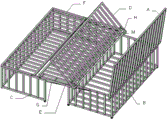
Fig. 1 is a structural diagram of an embodiment of the present invention.
Fig. 2 is a view showing each bed board of the embodiment of the present invention in a flat state.
Fig. 3 is a view showing the head bed board of the embodiment of the utility model in a tilted state.
Fig. 4 is a vertical view of the head bed board of the embodiment of the present invention.
Fig. 5 is a view showing the inclined placement of the bed board in the embodiment of the utility model.
Fig. 6 is a vertical view of the bed board in the embodiment of the utility model.
Fig. 7 is a view showing that the headboard is turned up on the headboard to store and take articles from the storage box when the bed boards are all laid flat for use. Fig. 8 and 9 are views showing the head bed board and the middle bed board respectively turning up the head bed board and storing and taking articles from the storage box when the head bed board is obliquely placed for use. Fig. 10, fig. 11 and fig. 12 are views respectively showing the article storage box being accessed from the corresponding bed board on the headstock by turning up the corresponding bed board when the bed board is inclined and the middle bed board is erected for use.
Examples in the drawings include A-a headboard, B-a headboard, C-a tailstock, D-a head board, E-a middle board, F-a tailstock board, G-a distance limiting chain, H-a limiting chain, K-a distance connecting piece, M-a circular guide rail, N-a strip guide rail, B11-a headboard head upright post, B12-a headboard tail upright post, B21-a storage box side frame, B22-a storage box cross frame, B23-a storage box underframe, B31-a self-braking universal wheel, B32-a common universal wheel, C11-a tailstock head upright post, C12-a tailstock tail upright post, C21-a tailstock side frame, C22-a tailstock cross frame, C3-a common universal wheel, C4-a tailstock frame face transverse connecting rod and C5-a hinge.
Detailed Description
In order to make the technical solution of the present invention better understood, the technical solution of the present invention is described below in detail and completely with reference to the accompanying drawings in the embodiments of the present invention. It is obvious that the described embodiments are only some of the embodiments of the present invention, and all other embodiments obtained by those skilled in the art without any inventive work shall fall within the scope of the present invention.
It should be noted that the terms "first," "second," and the like in the description and claims of this application and in the above-described drawings are used for distinguishing between similar elements and not necessarily for describing a particular sequential or chronological order. It is to be understood that the data so used may be interchanged where appropriate to facilitate description. Furthermore, the terms "comprises," "comprising," and any variations thereof, are intended to cover, not be exclusive, of inclusion.
The terms "long", "short", "wide", "longitudinal", "lateral", "up", "down", "front", "back", "left", "right", "horizontal", "vertical", "oblique", "top", "bottom", "inner", "outer", "head", "tail" and the like indicate the orientation or positional relationship based on the orientation or positional relationship shown in the drawings, which is only for convenience of description of the present invention and simplification of description, but does not indicate or imply that the device or component referred to must have a specific orientation, be constructed and operated in a specific orientation, and thus, should not be construed as limiting the present invention. Moreover, some of the above terms may be used to indicate other meanings besides orientation or position, for example, the term "on" may also be used to indicate some kind of dependency or connection in some cases. The specific meaning of these terms in the present invention can be understood by those of ordinary skill in the art as appropriate.
In addition, in the present invention, unless otherwise explicitly specified or limited, a quantity may explicitly or implicitly include one or more, and "plurality" means two or more. The terms "disposed," "provided," "mounted," "connected," "fixed," and the like are to be construed broadly, e.g., as meaning a fixed connection, a removable connection, or an integral entity; the connection may be direct or indirect, or the communication between two devices or components may be internal. The specific meaning of the above terms in the present invention can be understood by those of ordinary skill in the art according to their specific situation.
It should be noted that, in the case of conflict, the features of the present invention and the embodiments may be combined with each other. The present invention will be described in detail below with reference to the attached drawings, in which examples of the embodiments are shown, wherein like reference numerals designate identical or similar structural elements throughout.
As shown in fig. 1, the bed of the present embodiment mainly includes: the bed head board A, the bed head board B, the bed tail board C, the head board D, the middle board E, the tail board F, the distance limiting chain G, the limiting chain H, the distance connecting piece K, the round guide rail M and the strip-shaped guide rail N; the headstock B is formed by connecting and enclosing 4 headstock columns B1, 2 storage box side frames B21, 2 storage box cross frames B22 and 1 storage box underframe B23 according to the figure, is in a box shape without a cover and is used for supporting a bed board and storing articles; the tailstock C is formed by connecting 4 tailstock columns C1, 2 tailstock side frames C21, 1 tailstock cross frame C22 and 1 tailstock frame surface cross connecting rod C4 as shown in the figure and is in a U-shaped frame shape, and a supporting bed board and a storage box for temporarily containing the headstock B are all embedded into the U-shaped frame of the tailstock C; the distance limiting chain G is connected with the head frame B and the tail frame C to form the integral bedstead of the embodiment together, wherein one end of the distance limiting chain G is fixed at the upper end of a head upright C11 of the fixed bed tail frame, the other end of the distance limiting chain G is fixed at the middle point of the upper part of a side frame B21 of the storage box, and the two fixed points are positioned on the same level; the length of the distance limiting chain G ensures that the middle bed board E can be stably placed when all bed boards of the bed are completely laid, and meanwhile, the middle bed board E cannot slide off the bed head frame B or the bed tail frame C due to the fact that the distance between the bed head frame B and the bed tail frame C is too far, and ensures that the storage box can be embedded into the U-shaped bed frame of the bed tail frame C to the maximum extent when the bed is folded into a chair shape, so that the occupied area and the occupied space of the bed of the embodiment are reduced as much as possible; the width of the head bed board D is smaller than that of the head bed board B, and the width of the tail bed board F is smaller than that of the tail bed frame C, so that the head bed board B and the tail bed frame C have sufficient space to place the middle bed board E; the width of the head bed board D, the middle bed board E and the tail bed board F can be equal or unequal; the head bed board D, the middle bed board E and the tail bed board F are connected into a whole through a limiting chain H and a distance connecting piece K in sequence to form the whole bed board of the embodiment. The integral bed board is arranged on the integral bed frame and is connected through a bed tail frame surface transverse connecting rod C4 and a hinge C5 to form the bed of the embodiment, as shown in figure 2.
In particular, as shown in fig. 1, a circular guide rail M is arranged under the head bed plate D; a strip-shaped guide rail N is arranged below the middle bed plate E, and the strip-shaped guide rail N is intersected with the lower plane of the middle bed plate E at a small angle to form an inclined shape. When the head bed plate D and the middle bed plate E slide on the head frame side frame B21, the circular guide rail M and the strip-shaped guide rail N can respectively guide the head bed plate D and the middle bed plate E to slide on the head frame side frame B21 along the head-tail direction of the embodiment bed, and respectively restrain the head bed plate D and the middle bed plate E from transversely deviating and moving towards the left and right direction of the embodiment bed, so that the head bed plate D and the middle bed plate E are prevented from falling off the head frame side frame B21; further, the bed tail frame C is guided to move only in the longitudinal direction along the head-tail direction of the bed, and the bed tail frame C is restrained from moving laterally away from the left and right sides of the bed.
Specifically, as shown in fig. 1, a universal wheel B31 with a self-braking function is mounted at the near-ground end of the headstock head column B11, a common universal wheel B32 without a self-braking function is mounted at the near-ground end of the headstock tail column B12, and a common universal wheel C3 without a self-braking function is mounted at the near-ground end of the headstock head column C11. When the B31 is in a non-braking state, the headstock B can be flexibly and easily moved to any direction under the sliding action of the universal wheels B31 and B32; when the B31 is in the braking state, the headstock B can be well parked and kept still under the braking parking action of the B31. When 2 tailstock tail columns C12 at the tail part of the bed are lifted off the ground, the tailstock C can be easily moved to any direction under the sliding action of the universal wheels C3; when the 2 tailstock tail columns C12 contact with the ground, the tailstock C can be well parked in a static state.
As shown in any one of fig. 2, fig. 3, fig. 4, fig. 5, fig. 6, fig. 7, fig. 8, fig. 9, fig. 10, fig. 11 and fig. 12, the bed of the embodiment can be kept stable and still under the combined action of the brake stay of the bed B31 and the landing stay of the tailstock tail column C12 and under the action of a large external force within a certain limit no matter how pushed or pulled.
Particularly, as shown in any one of fig. 3, 4, 7 and 9, a limiting chain H is arranged between the head bed plate D and the middle bed plate E to connect the head bed plate D and the middle bed plate E, on one hand, the limiting chain H enables the head bed plate D to flexibly rotate along the edge of the near middle bed plate E, changes the state of the head bed plate D to be horizontal or inclined or vertical, enables the adjacent edge distance between the head bed plate D and the middle bed plate E to flexibly change as required, and further enables the middle bed plate E to move towards the head bed plate D in a partially overlapped manner until the two are completely overlapped; the limiting chain H simultaneously limits the proper maximum distance between the adjacent edges of the head bed plate D and the middle bed plate E when the head bed plate D is not horizontally arranged on the bed frame and the middle bed plate E is horizontally arranged on the bed frame, and prevents bed cushions from being damaged due to too close distance or bed articles from falling from a gap between the head bed plate D and the middle bed plate E due to too far distance; on the other hand, the limiting chain H enables the head bed plate D to slide on the side frame B21 of the head bed plate along with the driving of the middle bed plate E by the fore-and-aft movement of the tailstock C. When the head bed plate D and the middle bed plate E slide on the side frame B21 of the head frame under the driving of the front-back movement of the tailstock C, under the guide and constraint action of the circular guide rail M, the strip-shaped guide rail N and the limit chain H, the head bed plate D and the middle bed plate E can only longitudinally slide along the head-tail direction of the embodiment bed and can not transversely shift to the left side and the right side of the embodiment bed, so that the head bed plate D and the middle bed plate E are stably placed on the head frame B and can not fall off from the head frame B, and the tailstock C is further guided to longitudinally move only along the head-tail direction.
In particular, as shown in any one of fig. 5, 6, 10, 11 and 12, the distance connectors K are arranged between the middle bed plate E and the tail bed plate F to connect the middle bed plate E and the tail bed plate F. On one hand, the distance connecting piece K enables the middle bed board E to flexibly rotate along the edge close to the tail bed board F, changes the middle bed board E to be horizontal or inclined or vertical until the middle bed board E is overlapped with the bed tail board F, and also enables the tail bed board F to flexibly rotate along the edge close to the middle bed board E, changes the tail bed board F to be horizontal or inclined or vertical; on the other hand, the distance connecting piece K restrains two adjacent edges of the middle bed board E and the tail bed board F, and can keep a proper distance according to actual needs, so that the phenomenon that the mattress is damaged due to too close distance or articles on the bed fall from a gap between the middle bed board E and the tail bed board F due to too far distance is prevented. When the middle bed board E rotates upwards along the edge close to the tail bed board, under the common constraint of the distance connecting piece K and the strip-shaped guide rail N, the middle bed board E can only rotate and can not transversely move towards the left side and the right side of the embodiment bed, so that the middle bed board E is stably placed on the bed tail frame C and can not fall off the bed tail frame C; when the middle bed board E is inclined or erected, as shown in fig. 5 and 6, the middle bed board E can slide on the side frame B21 of the head frame by being driven by the fore-and-aft movement of the tailstock C. When the middle bed board E slides on the side frames B21 of the bed head, the strip-shaped guide rails N and the distance connectors K guide and restrain the middle bed board E to only longitudinally slide along the head-tail direction of the embodiment bed and not to transversely shift towards the left side and the right side of the bed, so that the middle bed board E is stably placed on the bed head B and cannot fall off from the bed head B, and meanwhile, the bed tail frame C is further guided to longitudinally move along the head-tail direction.
In particular, as shown in any one of fig. 2, 3, 4, 5 and 6, the headstock B is kept still under the brake staying action of B31, when 2 tailstock tail columns C12 are lifted off, and simultaneously the tailstock C is pushed or pulled under the sliding action and the guide of the common universal wheels C3, the tailstock C can easily approach or separate from the headstock B when the headstock D is slightly lifted up to approach the side of the headboard and the middle bed plate E is slightly lifted up to approach the side of the headboard; further, the tailstock C can only perform reciprocating movement in the longitudinal direction, with a limited distance, or close to or far from the headstock B along the head-tail direction of the bed under the guidance and restriction of the distance limiting chain G and the circular guide rail M and the strip-shaped guide rail N.
As shown in fig. 2, when 2 tailstock tail columns C12 are lifted off, the embodiment bed is kept still under the brake staying action of B31, the tailstock C is matched to lift up the head bed plate D to be close to one side of the headboard slightly, and the tailstock C is pushed along the head-tail direction of the embodiment bed, under the sliding assistance and guidance of the common universal wheels C3 and the guidance and restraint of the circular guide rails M and the strip-shaped guide rails N, the tailstock C can easily move close to the headboard B and drive each bed plate to move towards the head of the bed, and the head bed plate D leans against the headboard a with gradually increasing inclination angle, and is in the shape shown in fig. 3.
Further, as shown in fig. 3, when 2 tailstock tail columns C12 are lifted off the ground, the bed of the embodiment keeps static under the brake staying action of B31, and the tailstock C is pushed in the head-tail direction of the bed of the embodiment in cooperation with the upward slight lifting of the head bed board D near the headboard side, and the tailstock C continues to move close to the headboard B under the sliding assistance and guidance of the common universal wheels C3 and the guidance and restraint of the circular guide rails M and the strip-shaped guide rails N, and drives the bed boards to move towards the headboard a, so that the inclination angle of the head bed board D is further increased, and finally the head bed board D is close to the vertical position and leans against the headboard a, and is in the shape shown in fig. 4.
Further, as shown in fig. 4, when 2 tailstock tail columns C12 are lifted off the ground, the bed of the embodiment keeps static under the brake staying action of B31, the tailstock C is pushed along the head-tail direction of the bed of the embodiment in cooperation with upward slight lifting of the middle bed plate E near one side of the head bed plate, the tailstock C continues to move close to the head bed plate B under the sliding assistance and guidance of the common universal wheels C3 and the guidance and restraint of the strip-shaped guide rails N, and drives the middle bed plate E and the tail bed plate F to move towards the bed head, and the middle bed plate E leans against the head bed plate D with gradually increasing the inclination angle, and is shaped as shown in fig. 5.
Further, as shown in fig. 5, when 2 tailstock tail columns C12 are lifted off the ground, the bed of the embodiment keeps static under the brake staying action of B31, the middle bed plate E is lifted up slightly to be close to one side of the head bed plate, the tailstock C is pushed along the head-tail direction of the bed of the embodiment, the tailstock C continues to move close to the head bed plate B under the sliding assistance and guidance of the common universal wheels C3 and the guidance and restraint of the strip-shaped guide rails N, and drives the middle bed plate E and the tail bed plate F to move towards the bed head, the inclination angle of the middle bed plate E is further increased, and finally the middle bed plate E is close to the vertical position to be close to the head bed plate D, and is in the shape shown in fig. 6.
When the embodiment bed is in the state shown in fig. 6, when 2 tailstock tail columns C12 are lifted off the ground, the embodiment bed is kept still under the brake staying action of B31, the tailstock C is dragged along the head-tail direction of the embodiment bed, the tailstock C can easily get away from the headstock B under the sliding assistance and guidance of a common universal wheel C3 and the guidance and restraint of a strip-shaped guide rail N, and drives the tail bed board F and the middle bed board E to move towards the tail end direction of the bed, and the middle bed board E gradually turns to an inclined state from a nearly vertical state to be close to the vertically placed head bed board D, and takes the state shown in fig. 5; the middle bed board E further reduces the inclination angle with the continuous backward dragging of the tailstock C, and finally is horizontally placed on the bed frame in the shape shown in figure 4.
Further, as shown in fig. 4, when 2 tailstock tail columns C12 are lifted off the ground, the bed of the embodiment remains stationary under the brake staying action of B31, and the tailstock C is continuously dragged towards the bed tail end, the tailstock C further moves away from the headstock B under the sliding assistance and guidance of the common universal wheels C3 and the guidance and restraint of the strip-shaped guide rails N and the circular guide rails M, and drives each bed board to move towards the bed tail end, and the head bed board D gradually changes from a nearly vertical shape to an inclined shape and leans against the headboard a to take the shape shown in fig. 3; the head bed plate D further reduces the inclination angle along with the continuous backward dragging of the tailstock C until the head bed plate D is horizontally arranged on the headstock B; finally, the bed tailstock C cannot be dragged backwards due to the constraint action of the limited distance chain G in a tension state because of being straightened, and the bed in the embodiment is in a fully unfolded state shown in figure 2.
When the embodiment bed is folded into a shape shown in fig. 6, the B31 is placed in a non-braking state, the tail upright post C12 of the bed tailstock is lifted off the ground and the embodiment bed is pushed and pulled, and the embodiment bed can be easily moved to other places in a room where the embodiment bed is needed by virtue of the flexible sliding action of the C3, the B32 and the B31, so that convenience is provided for cleaning and sanitation work under the bed.
When the embodiment bed is in the shape shown in fig. 2, the head bed board D is turned upwards to be obliquely placed or vertically placed, even overlapped with the middle bed board E, as shown in fig. 7, the storage box of the headstock B is exposed, and articles are convenient to store and take from the storage box; the embodiment bed is in the state shown in fig. 3, the bed head board D or the middle board E is turned over as shown in fig. 8 and 9, the middle board E is turned over when the embodiment bed is in the state shown in fig. 4, the middle board E is turned over when the embodiment bed is in the state shown in fig. 5, and the bed tail board F is turned over when the embodiment bed is in the state shown in fig. 6, and the headstock B storage box is exposed for conveniently storing and taking articles from the storage box as shown in fig. 10, 11 and 12.
It should be understood that the present invention is not limited to the embodiment in which the storage box is disposed on the head frame and the "U" shaped bed frame is disposed on the tail frame, but in some embodiments, the storage box can be disposed on the middle portion or the tail portion of the bed frame, the "U" shaped bed frame can be disposed on the head portion or the middle portion of the bed frame, and more than 1 storage box or "U" shaped bed frame can be disposed.
The embodiment of the utility model provides a use materials such as bedstead, bed board are not limited to the wood, also can use all kinds of artifical panel, metal material, plastic material or other. Headboard A, storage box side frame B21, cross frame B22 and underframe B23, tailstock side frame C21 and cross frame C22, which can be in various forms, such as plate, or rail, or frame; can be in various shapes, such as square, flower type or hollow shape; the distance limiting chain G and the limiting chain H can be ropes made of flexible materials or chains made of hard materials; the distance connecting piece K, the round guide rail M and the strip-shaped guide rail N are preferably made of hard materials such as metal or plastic with higher strength.
The embodiment of the utility model provides a specification of bed, the suggestion is but not limited to following specification: the height of the bed frame is 30-50 cm, the height of the bed head plate is 40-80 cm, the length of the bed (namely the sum of the widths of the three bed plates of the head bed plate D, the middle bed plate E and the tail bed plate F) is 180-220 cm, and the width of the bed (namely the length of the three bed plates) is determined according to the requirement and is 50-200 cm in general.
For increasing the utility model discloses the outer pleasing to the eye degree of bed uses comfortable experience degree with the improvement user, and convenient the utility model discloses a bed draws in or expandes, leads to storage box volume undersize because of the mattress is too thick simultaneously, generally adds the mattress or the cover of spreading coconut palm mattress, foam mattress etc. and each bed board size matching unanimity on the bed board.
In order to reduce the physical strength consumption of a user when the embodiment bed is unfolded and folded and increase the flexibility of the unfolding and folding bed, the near end of the tail upright C12 of the tailstock of the bed frame of the embodiment bed, which directly lands on the ground and resides on the bed frame, can be additionally provided with a pulley with a braking part, and the pulley braking function is started to realize the residing effect on the embodiment bed; when the braking function of the pulleys is suspended, the bed can be unfolded or folded more conveniently and easily, or the bed can be moved integrally.
In the embodiment, after the headboard A is detached from the bed and the distance limiting chain G is disconnected from the headboard B, namely the storage box, can be used as a baby bed.
When moving, the distance limiting chain G is disconnected and the headboard A is detached, all the components can pass through the bedroom door, and the moving, detaching and installing are convenient; the storage box can be temporarily used as a storage box for containing articles for moving after being disassembled, and the tailstock, all bed boards and the headboard A are slightly bound and fixed, so that the tailstock can be used as a temporary storage box for containing articles for moving.
The above description is illustrative of the present invention, but is only the preferred embodiment of the present invention, and should not be considered as limiting the scope of the invention. The equivalent changes and improvements made within the scope of the present invention should be included in the patent coverage of the present invention.
Claims (10)
1. A bed, comprising: the bed head board, the bed head frame, the bed tail frame, the head bed board, the middle bed board, the tail bed board, the distance limiting chain, the distance connecting piece, the circular guide rail and the strip-shaped guide rail; the headboard is fixed on the headboard, and the headboard and the tailstock are connected through a distance limiting chain to form an integral bedstead; the head bed plate, the middle bed plate and the tail bed plate are connected in sequence through a limiting chain and a fixed-distance connecting piece to form an integral bed plate; the head bed board is arranged on the head bed frame, the tail bed board is arranged on the tail bed frame, and two sides of the middle bed board are respectively arranged on the head bed frame and the tail bed frame to form the bed.
2. The bed of claim 1, wherein the frame is divided into at least two sections, one of which is a storage box and the other is a "U" shaped frame, and the storage box can be completely embedded in the "U" shaped frame.
3. The bed of claim 1, wherein the deck is divided into at least two sections, a head deck and a tail deck.
4. The bed of claim 1, wherein a distance chain is provided between the head frame and the foot frame, the distance chain connecting the head frame and the foot frame.
5. The bed of claim 1, wherein a circular guide is provided under the head deck.
6. The bed of claim 1, wherein a spacing chain is provided between the head deck and the middle deck, the spacing chain connecting the head deck and the middle deck.
7. The bed of claim 1, wherein a strip-shaped guide rail is arranged below the middle bed plate.
8. The bed of claim 1, wherein a distance connector is provided between the middle bed plate and the end bed plate, the distance connector connecting the middle bed plate and the end bed plate.
9. The bed of claim 1, wherein a bed tailstock frame face transverse connecting rod is arranged at the upper end of the bed tailstock frame side frame, and a hinge is arranged on the connecting rod; the bed tail frame is reinforced by the bed tail frame surface transverse connecting rod, and the bed tail frame surface connecting rod and the hinge jointly connect the tail bed board and the bed tail frame together.
10. The bed of claim 1, wherein the headstock carries at least 2 pulleys and the tailstock carries at least 2 pulleys, said pulleys having self-braking capability.
Priority Applications (1)
| Application Number | Priority Date | Filing Date | Title |
|---|---|---|---|
| CN202021948634.7U CN212233824U (en) | 2020-09-09 | 2020-09-09 | Multifunctional storage bed capable of contracting, unfolding and deforming |
Applications Claiming Priority (1)
| Application Number | Priority Date | Filing Date | Title |
|---|---|---|---|
| CN202021948634.7U CN212233824U (en) | 2020-09-09 | 2020-09-09 | Multifunctional storage bed capable of contracting, unfolding and deforming |
Publications (1)
| Publication Number | Publication Date |
|---|---|
| CN212233824U true CN212233824U (en) | 2020-12-29 |
Family
ID=73981777
Family Applications (1)
| Application Number | Title | Priority Date | Filing Date |
|---|---|---|---|
| CN202021948634.7U Active CN212233824U (en) | 2020-09-09 | 2020-09-09 | Multifunctional storage bed capable of contracting, unfolding and deforming |
Country Status (1)
| Country | Link |
|---|---|
| CN (1) | CN212233824U (en) |
-
2020
- 2020-09-09 CN CN202021948634.7U patent/CN212233824U/en active Active
Similar Documents
| Publication | Publication Date | Title |
|---|---|---|
| US10021989B2 (en) | Modular user-assembled adjustable, and high-low adjustable beds | |
| US10820711B2 (en) | Extended-range versatilely-configurable user-assembled adjustable, and high-low adjustable, beds | |
| US4204287A (en) | Knock-down sofa bed with hinged mattress | |
| US4586206A (en) | Convertible sofa-bed arrangement | |
| US9844274B2 (en) | Modular user-assembled adjustable, and high-low adjustable beds | |
| US20080276872A1 (en) | Foldable pet bed | |
| CA2045308A1 (en) | Hospital bed particularly for home care | |
| US8894138B2 (en) | Collapsible mobile furniture frame | |
| CN101019796B (en) | Multifunctional folding wheel chair bed | |
| CN212233824U (en) | Multifunctional storage bed capable of contracting, unfolding and deforming | |
| CN114224116A (en) | Multifunctional storage bed capable of contracting, unfolding and deforming | |
| CN2380209Y (en) | Multifunction high-grade medical bed | |
| CN201131863Y (en) | Supporting structure of bedstead group | |
| CN209916434U (en) | Rehabilitation nursing bed | |
| CN2168481Y (en) | Multifunctional folding bed | |
| CN2400010Y (en) | Multi-purpose chair | |
| CN2468380Y (en) | Folding spring soft bed | |
| CN218792799U (en) | Quick expansion medical nursing bed | |
| CN2234218Y (en) | Multifunctional chair | |
| CN2728318Y (en) | Folding multipurpose sofa | |
| CN220384721U (en) | Hospital accompanying bed with expandable width | |
| CN2596863Y (en) | Movable chair | |
| CN218484138U (en) | Dustproof sofa structure | |
| CN211382296U (en) | Medical multifunctional bed | |
| JP3062390U (en) | Rollaway bed with chair function |
Legal Events
| Date | Code | Title | Description |
|---|---|---|---|
| GR01 | Patent grant | ||
| GR01 | Patent grant |