CN212230967U - Cable laying device for power engineering - Google Patents
Cable laying device for power engineering Download PDFInfo
- Publication number
- CN212230967U CN212230967U CN202020900142.4U CN202020900142U CN212230967U CN 212230967 U CN212230967 U CN 212230967U CN 202020900142 U CN202020900142 U CN 202020900142U CN 212230967 U CN212230967 U CN 212230967U
- Authority
- CN
- China
- Prior art keywords
- rigid coupling
- power engineering
- plate
- sheave
- backup pad
- Prior art date
- Legal status (The legal status is an assumption and is not a legal conclusion. Google has not performed a legal analysis and makes no representation as to the accuracy of the status listed.)
- Active
Links
Images


Landscapes
- Electric Cable Installation (AREA)
Abstract
The utility model discloses a cable laying device for power engineering, including bottom plate, universal wheel, backup pad and protective case, the universal wheel is all installed in the lower surface four corners of bottom plate, the upper surface intermediate position rigid coupling of bottom plate has the backup pad, the upper surface rigid coupling of bottom plate has the protective case, the top rigid coupling of backup pad has fixed establishment. This cable laying device for power engineering, through linking the board, the horizontal pole, first bearing, the cooperation of chuck and bolt etc. is used, can lay two kinds of cables simultaneously, and then increase whole mechanism's practicality, through double threaded rod, the second bearing, the carousel, the cooperation of thread bush and fixture block etc. is used, the thread bush drives the arris shape piece through the L shaped plate and fixes the sheave, be favorable to using widely, through the diaphragm, the montant, the backing plate, the cooperation of rand and connecting pin etc. is used, make things convenient for the installation and the dismantlement of sheave, satisfy the user demand to cable laying device among the electric power engineering greatly.
Description
Technical Field
The utility model relates to a cable laying technical field specifically is a cable laying device for power engineering.
Background
Electric power engineering, i.e. engineering related to the production, transmission and distribution of electric energy, also broadly includes engineering of applying electricity as power and energy in various fields, in which electric power engineering cables are often used, and cable laying devices are required to increase construction efficiency, for example, application numbers of: 201820674146.8, neotype cable laying device for power engineering can realize right the automatic locking of drum shaft prevents at the laying process, the cylinder is followed roll off on the support, has avoided the emergence of incident to use simple laborsaving, safe convenient, but current cable laying device for power engineering can only lay a cable simultaneously, has the limitation during the use, leads to whole mechanism's practicality to descend, and the sheave quality that has the cable is heavier, inconvenient installation and dismantlement, hardly satisfies the user demand to cable laying device among the power engineering.
Disclosure of Invention
An object of the utility model is to provide a cable laying device for power engineering to propose current cable laying device for power engineering in solving above-mentioned background art, can only lay a cable simultaneously, have the limitation during the use, lead to the problem that the practicality of whole mechanism descends.
In order to achieve the above object, the utility model provides a following technical scheme: a cable laying device for an electric power engineering comprises a bottom plate, universal wheels, supporting plates and a protective shell, wherein the universal wheels are mounted at four corners of the lower surface of the bottom plate, the supporting plates are fixedly connected to the middle position of the upper surface of the bottom plate, the protective shell is fixedly connected to the upper surface of the bottom plate, and a fixing mechanism is fixedly connected to the top ends of the supporting plates;
the fixing mechanism comprises a connecting plate, a cross rod, a first bearing, a chuck and a bolt;
the bottom of even board and backup pad looks rigid coupling, the inside of even board is equipped with the horizontal pole, the horizontal pole passes through first bearing and links to each other with even board activity, the equal rigid coupling in both ends has the chuck about the horizontal pole, two the equal threaded connection of outer wall of chuck has the bolt. Two cables are installed at the same time, and the application range of the whole mechanism is enlarged.
Preferably, the chucks are symmetrically distributed about the crossbar. The grooved wheel is convenient to install.
Preferably, a grooved wheel is sleeved in the chuck, the grooved wheel is in clearance fit with the chuck, a prismatic block is sleeved at one end, away from the chuck, of the grooved wheel, the prismatic block is in clearance fit with the grooved wheel, and an L-shaped plate is movably connected at one end, away from the grooved wheel, of the prismatic block. The fixing with the grooved pulley is convenient.
Preferably, a transmission mechanism is arranged in the protective shell;
the transmission mechanism comprises a double-threaded rod, a second bearing, a rotary table, a threaded sleeve and a clamping block;
the outer wall of double threaded rod passes through the second bearing and links to each other with the protecting crust activity, double threaded rod's right-hand member rigid coupling has the carousel, double threaded rod's outer wall and backup pad clearance fit, double threaded rod's outer wall threaded connection has the thread bush, two the fixture block has all been processed to the outer wall of thread bush, the outer wall of fixture block and the inside recess clearance fit of protecting crust, the top and the L shaped plate looks rigid coupling of thread bush. Power the movement of the L-shaped plate. Is convenient to use.
Preferably, the threaded sleeve and the protective shell form a sliding mechanism. The movement of the thread bush is convenient.
Preferably, the threaded sleeve is arranged in parallel with the support plate. The screw sleeve is favorable for driving the L-shaped plate to move.
Preferably, a supporting mechanism is installed inside the supporting plate;
the supporting mechanism comprises a transverse plate, a vertical rod, a base plate, a clamping ring and a connecting pin;
two the one end and the backup pad activity of diaphragm link to each other, the other end rigid coupling of diaphragm has the montant, the top rigid coupling of montant has the backing plate, the upper surface and the sheave of backing plate are laminated mutually, the upper surface rigid coupling of diaphragm has the rand, the inside threaded connection of rand has the connecting pin, the outer wall of connecting pin runs through rand and backup pad threaded connection. The auxiliary function is achieved when the grooved wheel is installed.
Preferably, the backing plate is perpendicular to the vertical rod. The vertical rods have a supporting function on the base plate.
Compared with the prior art, the beneficial effects of the utility model are that: this cable laying device for electric power engineering compares traditional technique, has following advantage:
through the cooperation use of even board, horizontal pole, first bearing, chuck and bolt etc, the chuck passes through the horizontal pole and rotates in even board, and two sheaves can be installed to two chucks, can lay two kinds of cables simultaneously, and then increase whole mechanism's practicality.
Through the cooperation use of double threaded rod, second bearing, carousel, thread bush and fixture block etc. rotate the carousel and drive double threaded rod and rotate in the protecting crust, and double threaded rod's rotation drives two thread bushes and passes through the fixture block and move in opposite directions in the recess of protecting crust, and the thread bush drives the arris shape piece through the L shaped plate and fixes the sheave, is favorable to using widely.
Through the cooperation use of diaphragm, montant, backing plate, rand and connecting pin etc. when diaphragm and backup pad were perpendicular, use the connecting pin to run through the rand and carry out the rigidity to the diaphragm, the diaphragm drives the backing plate pad in the bottom of sheave, makes things convenient for the installation and the dismantlement of sheave, satisfies the user demand to cable laying device among the power engineering greatly.
Drawings
FIG. 1 is a schematic structural view of the present invention;
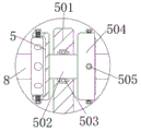
FIG. 2 is a schematic view of a connection structure of the fixing mechanism and the sheave shown in FIG. 1;
FIG. 3 is a schematic view of the connection structure between the transmission mechanism and the L-shaped plate in FIG. 1;
fig. 4 is a schematic view of a connection structure between the support mechanism and the support plate in fig. 1.
In the figure: 1. the device comprises a bottom plate, 2, universal wheels, 3, a supporting plate, 4, a protective shell, 5, a fixing mechanism, 501, a connecting plate, 502, a cross rod, 503, a first bearing, 504, a chuck, 505, a bolt, 6, a transmission mechanism, 601, a double-threaded rod, 602, a second bearing, 603, a turntable, 604, a threaded sleeve, 605, a fixture block, 7, a supporting mechanism, 701, a transverse plate, 702, a vertical rod, 703, a base plate, 704, a clamping ring, 705, a connecting pin, 8, a grooved wheel, 9, a prismatic block, 11 and an L-shaped plate.
Detailed Description
The technical solutions in the embodiments of the present invention will be described clearly and completely with reference to the accompanying drawings in the embodiments of the present invention, and it is obvious that the described embodiments are only some embodiments of the present invention, not all embodiments. Based on the embodiments in the present invention, all other embodiments obtained by a person skilled in the art without creative work belong to the protection scope of the present invention.
Referring to fig. 1-4, the present invention provides a technical solution: a cable laying device for electric power engineering comprises a bottom plate 1, universal wheels 2, a supporting plate 3 and a protective shell 4, wherein the universal wheels 2 are arranged at four corners of the lower surface of the bottom plate 1, the universal wheels 2 drive an integral mechanism to move, the supporting plate 3 is fixedly connected to the middle position of the upper surface of the bottom plate 1, the protective shell 4 is fixedly connected to the upper surface of the bottom plate 1, a fixing mechanism 5 is fixedly connected to the top end of the supporting plate 3, the fixing mechanism 5 comprises a connecting plate 501, the cross rod 502, a first bearing 503, chucks 504 and bolts 505, the bottom end of the connecting plate 501 is fixedly connected with the supporting plate 3, the cross rod 502 is arranged inside the connecting plate 501, the cross rod 502 is movably connected with the connecting plate 501 through the first bearing 503, the cross rod 502 rotates in the connecting plate 501 through the first bearing 503, the chucks 504 are fixedly connected to the left end and the right end of the cross rod 502, the bolts 505 are in threaded connection with the outer walls of the two chucks 504, the bolts 505 fix the grooved pulley 8, and the chucks 504 are symmetrically distributed about the cross rod 502.
The sheave 8 has been cup jointed to the inside of chuck 504, sheave 8 and chuck 504 clearance fit, and the outer wall processing of sheave 8 has the screw hole, and the one end that the chuck 504 was kept away from to sheave 8 has cup jointed arris shape piece 9, and arris shape piece 9 can block into the left and right sides recess of sheave 8, and two arris shape pieces 9 all with sheave 8 clearance fit, and the one end swing joint that sheave 8 was kept away from to arris shape piece 9 has L shaped plate 11.
The internally mounted of protecting shell 4 has drive mechanism 6, drive mechanism 6 includes double threaded rod 601, second bearing 602, carousel 603, thread bush 604 and fixture block 605, double threaded rod 601's outer wall passes through second bearing 602 and protects shell 4 activity and links to each other, double threaded rod 601's right-hand member rigid coupling has carousel 603, double threaded rod 601's outer wall and backup pad 3 clearance fit, it drives double threaded rod 601 and rotates to rotate carousel 603, double threaded rod 601's outer wall threaded connection has thread bush 604, fixture block 605 has all been processed to the outer wall of two thread bushes 604, fixture block 605's outer wall and the inside recess clearance fit of protecting shell 4, thread bush 604 passes through fixture block 605 and moves in protecting shell 4, the top and the L shaped plate 11 looks rigid coupling of thread bush 604, thread bush 604 constitutes slide mechanism with protecting shell 4, thread bush 604 and backup pad 3 parallel arrangement.
Supporting mechanism 7 is installed to the internally mounted of backup pad 3, supporting mechanism 7 includes diaphragm 701, montant 702, backing plate 703, rand 704 and connecting pin 705, two diaphragm 701's one end links to each other with backup pad 3 activity, diaphragm 701 links to each other with backup pad 3 is articulated through the pin pole, diaphragm 701's other end rigid coupling has montant 702, montant 702's top rigid coupling has backing plate 703, the upper surface and the sheave 8 of backing plate 703 laminate mutually, diaphragm 701's upper surface rigid coupling has rand 704, the internal thread connection of rand 704 has connecting pin 705, the outer wall of connecting pin 705 runs through rand 704 and backup pad 3 threaded connection, connecting pin 705 runs through rand 704 and carries out the rigidity to diaphragm 701, backing plate 703 sets up with montant 702 is perpendicular.
In this example, when the device is used to lay cables, firstly, the transverse plate 701 is rotated in the support plate 3, when the transverse plate 701 is perpendicular to the support plate 3, the transverse plate 701 is fixed in position by penetrating the collar 704 through the connecting pin 705, then the sheave 8 with the cables is installed in the chuck 504, one end of the sheave 8 away from the chuck 504 can be placed on the upper surface of the backing plate 703, the bolt 505 is inserted into the threaded hole of the sheave 8 through the chuck 504 to fix the position of the sheave 8, then the rotating disc 603 is rotated to drive the double-threaded rod 601 to rotate in the protective shell 4 through the second bearing 602, as the rotation of the double-threaded rod 601 drives the two thread sleeves 604 to move oppositely in the groove of the protective shell 4 through the fixture 605, the thread sleeves 604 drive the L-shaped plate 11 to move, the L-shaped plate 11 drives the prismatic block 9 to be clamped into the sheave 8, then the connecting pin 705 is removed to accommodate the transverse plate, drive the whole mechanism through universal wheel 2 and remove, sheave 8 rotates in L shaped plate 11 through arris shape piece 9, and chuck 504 drives horizontal pole 502 and rotates in even board 501 simultaneously, and then the cable drops from sheave 8's outer wall and lays.
In the description of the present invention, it is to be understood that the terms "coaxial", "bottom", "one end", "top", "middle", "other end", "upper", "one side", "top", "inner", "front", "center", "both ends", and the like, indicate orientations or positional relationships based on the orientations or positional relationships shown in the drawings, and are only for convenience of description and simplicity of description, and do not indicate or imply that the device or element referred to must have a particular orientation, be constructed and operated in a particular orientation, and therefore, should not be construed as limiting the present invention.
In the present invention, unless otherwise expressly stated or limited, the terms "mounted," "disposed," "connected," "fixed," "screwed" and the like are to be construed broadly, e.g., as meaning fixedly connected, detachably connected, or integrally formed; can be mechanically or electrically connected; they may be directly connected or indirectly connected through an intermediate medium, and may be connected through the inside of two elements or in an interaction relationship between two elements, unless otherwise specifically defined, and the specific meaning of the above terms in the present invention will be understood by those skilled in the art according to specific situations.
Although embodiments of the present invention have been shown and described, it will be appreciated by those skilled in the art that changes, modifications, substitutions and alterations can be made in these embodiments without departing from the principles and spirit of the invention, the scope of which is defined in the appended claims and their equivalents.
Claims (8)
1. The utility model provides a cable laying device for power engineering, includes bottom plate (1), universal wheel (2), backup pad (3) and protective case (4), universal wheel (2) are all installed in the lower surface four corners of bottom plate (1), the upper surface intermediate position rigid coupling of bottom plate (1) has backup pad (3), the upper surface rigid coupling of bottom plate (1) has protective case (4), its characterized in that: the top end of the supporting plate (3) is fixedly connected with a fixing mechanism (5);
the fixing mechanism (5) comprises a connecting plate (501), a cross rod (502), a first bearing (503), a chuck (504) and a bolt (505);
the bottom and the backup pad (3) looks rigid coupling of even board (501), the inside of even board (501) is equipped with horizontal pole (502), horizontal pole (502) link to each other with even board (501) activity through first bearing (503), the equal rigid coupling in both ends has chuck (504), two about horizontal pole (502) the equal threaded connection of outer wall of chuck (504) has bolt (505).
2. A cabling arrangement for power engineering according to claim 1, characterized in that: the chucks (504) are symmetrically distributed about the crossbar (502).
3. A cabling arrangement for power engineering according to claim 1, characterized in that: sheave (8) have been cup jointed to the inside of chuck (504), sheave (8) and chuck (504) clearance fit, prism block (9) have been cup jointed to the one end that chuck (504) were kept away from in sheave (8), two prism block (9) all with sheave (8) clearance fit, the one end swing joint that sheave (8) were kept away from in prism block (9) has L shaped plate (11).
4. A cabling arrangement for power engineering according to claim 1, characterized in that: a transmission mechanism (6) is arranged in the protective shell (4);
the transmission mechanism (6) comprises a double-head threaded rod (601), a second bearing (602), a rotary disc (603), a threaded sleeve (604) and a clamping block (605);
the outer wall of double-threaded rod (601) passes through second bearing (602) and links to each other with protecting shell (4) activity, the right-hand member rigid coupling of double-threaded rod (601) has carousel (603), the outer wall and backup pad (3) clearance fit of double-threaded rod (601), the outer wall threaded connection of double-threaded rod (601) has thread bush (604), two fixture block (605) have all been processed to the outer wall of thread bush (604), the inner groove clearance fit of the outer wall of fixture block (605) and protecting shell (4), the top and the L shaped plate (11) looks rigid coupling of thread bush (604).
5. A cabling arrangement for power engineering according to claim 4, wherein: the threaded sleeve (604) and the protective shell (4) form a sliding mechanism.
6. A cabling arrangement for power engineering according to claim 4, wherein: the threaded sleeve (604) and the support plate (3) are arranged in parallel.
7. A cabling arrangement for power engineering according to claim 1, characterized in that: a supporting mechanism (7) is arranged in the supporting plate (3);
the supporting mechanism (7) comprises a transverse plate (701), a vertical rod (702), a backing plate (703), a clamping ring (704) and a connecting pin (705);
two the one end and the backup pad (3) activity of diaphragm (701) link to each other, the other end rigid coupling of diaphragm (701) has montant (702), the top rigid coupling of montant (702) has backing plate (703), the upper surface and sheave (8) of backing plate (703) are laminated mutually, the upper surface rigid coupling of diaphragm (701) has rand (704), the internal thread of rand (704) is connected with connecting pin (705), the outer wall of connecting pin (705) runs through rand (704) and backup pad (3) threaded connection.
8. An electrical power engineering cabling arrangement according to claim 7, wherein: the backing plate (703) is perpendicular to the vertical rod (702).
Priority Applications (1)
| Application Number | Priority Date | Filing Date | Title |
|---|---|---|---|
| CN202020900142.4U CN212230967U (en) | 2020-05-26 | 2020-05-26 | Cable laying device for power engineering |
Applications Claiming Priority (1)
| Application Number | Priority Date | Filing Date | Title |
|---|---|---|---|
| CN202020900142.4U CN212230967U (en) | 2020-05-26 | 2020-05-26 | Cable laying device for power engineering |
Publications (1)
| Publication Number | Publication Date |
|---|---|
| CN212230967U true CN212230967U (en) | 2020-12-25 |
Family
ID=73927989
Family Applications (1)
| Application Number | Title | Priority Date | Filing Date |
|---|---|---|---|
| CN202020900142.4U Active CN212230967U (en) | 2020-05-26 | 2020-05-26 | Cable laying device for power engineering |
Country Status (1)
| Country | Link |
|---|---|
| CN (1) | CN212230967U (en) |
-
2020
- 2020-05-26 CN CN202020900142.4U patent/CN212230967U/en active Active
Similar Documents
| Publication | Publication Date | Title |
|---|---|---|
| CN212230967U (en) | Cable laying device for power engineering | |
| CN113740985A (en) | Branching device for laying communication optical cables | |
| CN210880215U (en) | Small-size concrete mixer mounting bracket convenient to quick assembly disassembly | |
| CN211183219U (en) | Power cable winding displacement supports fixing device | |
| CN211110657U (en) | Large-span lifting appliance | |
| CN215797583U (en) | Cable coiling mechanism is used in installation of building water and electricity | |
| CN209793729U (en) | Combined lifting manipulator | |
| CN215057161U (en) | Derrick for petroleum drilling and repairing equipment | |
| CN210306097U (en) | Screw thread threading device is used in production of square plate casing | |
| CN212794699U (en) | Optical device positioning fixture convenient to install | |
| CN210578102U (en) | Fixed frame type motor | |
| CN212183071U (en) | Cable fixing device for municipal works | |
| CN213647276U (en) | Mechanical and electrical positioning device | |
| CN220148972U (en) | Module installation lifting appliance | |
| CN214923888U (en) | Automatic part clamping device with alarming function for motor assembly line | |
| CN213381424U (en) | Novel gear box maintenance device | |
| CN216929417U (en) | Electrical installation high-altitude operation pulley | |
| CN212220980U (en) | Protection architecture for electric valve | |
| CN212033910U (en) | Motor with direct-insert type connecting structure | |
| CN213204971U (en) | Connecting and locking device for building template | |
| CN215032467U (en) | Straightening equipment for part after processing | |
| CN212601680U (en) | V-shaped supporting block | |
| CN216917676U (en) | Grabbing device for machining | |
| CN215798071U (en) | Threading equipment for hoisting power equipment | |
| CN214412628U (en) | Photovoltaic cell module supporting mechanism |
Legal Events
| Date | Code | Title | Description |
|---|---|---|---|
| GR01 | Patent grant | ||
| GR01 | Patent grant |