CN212228562U - Device for rapidly detecting hardness of casting product - Google Patents
Device for rapidly detecting hardness of casting product Download PDFInfo
- Publication number
- CN212228562U CN212228562U CN202020953505.0U CN202020953505U CN212228562U CN 212228562 U CN212228562 U CN 212228562U CN 202020953505 U CN202020953505 U CN 202020953505U CN 212228562 U CN212228562 U CN 212228562U
- Authority
- CN
- China
- Prior art keywords
- threaded rod
- support frame
- sliding
- drawer
- rod
- Prior art date
- Legal status (The legal status is an assumption and is not a legal conclusion. Google has not performed a legal analysis and makes no representation as to the accuracy of the status listed.)
- Active
Links
Images


Abstract
The utility model discloses a device of short-term test foundry goods product hardness, including base and motor, the inside drawer that is provided with of base, and the drawer is inside to have seted up and to accomodate the groove, the base upper end is provided with the threaded rod, and the threaded rod end is connected with the diaphragm, diaphragm surface mounting has the motor, and the motor output end is connected with the threaded rod, the threaded rod surface is provided with the support frame, and the support frame end-to-end installs the stopper to the stopper is connected with the gag lever post, the inside mounting groove of having seted up of support frame, and the inside connecting block that is provided with of mounting groove, the splint lower extreme is provided with the slider, and the slider is connected. This device of short-term test foundry goods hardness drives the sclerometer through the support frame and removes, and the interval between user's accessible telescopic link regulation support frame and the sclerometer simultaneously to make the sclerometer can be quick carry out the short-term test to the work piece.
Description
Technical Field
The utility model relates to a foundry goods product technology field specifically is a device of short-term test foundry goods product hardness.
Background
The casting is a metal object obtained by a casting method, that is, a liquid metal obtained by smelting is poured into a casting mold prepared in advance by a casting method, an injection method and the like, and the object with certain shape, size and performance is obtained after processing, in order to ensure the quality of a casting product, the hardness of the casting product needs to be detected when the processing is finished, but the existing casting product hardness detection device has certain use defects, such as:
when the existing device is used, the workpiece cannot be quickly positioned according to the position of the workpiece, so that the working efficiency of a user is influenced, the workpiece is wide in application range, certain difference exists in the appearance of the workpiece, the existing device cannot be adjusted conveniently according to the shape of the workpiece, the device is limited when in use, the existing device does not have a storage function, and the practicability of the device is low.
SUMMERY OF THE UTILITY MODEL
An object of the utility model is to provide a device of short-term test foundry goods product hardness to propose current device can not fix a position fast in solving above-mentioned background art, and the person of facilitating the use adjusts, and does not have the problem of accomodating the function.
In order to achieve the above object, the utility model provides a following technical scheme: a device for rapidly detecting the hardness of a casting product comprises a base and a motor, wherein a drawer is arranged in the base, a containing groove is formed in the drawer, a threaded rod is arranged at the upper end of the base, the tail end of the threaded rod is connected with a transverse plate, the outer surface of the transverse plate is provided with the motor, the output end of the motor is connected with the threaded rod, the outer surface of the threaded rod is provided with a support frame, the tail end of the support frame is provided with a limiting block, the limiting block is connected with the limiting rod, a mounting groove is formed in the support frame, a connecting block is arranged in the mounting groove, the tail end of the connecting block is connected with a telescopic rod, a hardness tester is arranged at the tail end of the telescopic rod, a support plate is arranged at the upper, and the chute is arranged inside the workbench.
Preferably, the receiving grooves are equally spaced with respect to the inside of the drawer, and there is a difference in shape between the receiving grooves.
Preferably, the support frame forms a sliding structure with the limiting rod through the limiting block, and the support frame is in threaded connection with the threaded rod.
Preferably, the telescopic link passes through the connecting block and constitutes block structure with the mounting groove, and the length of connecting block equals with the degree of depth of mounting groove.
Preferably, the clamping plate forms a sliding structure through the sliding block and the sliding groove, and the transverse section of the sliding block is of a circular structure.
Preferably, the surface symmetry of workstation is provided with 2 splint, and splint transverse section is the rectangular structure.
Compared with the prior art, the beneficial effects of the utility model are that: the device for rapidly detecting the hardness of the casting product,
1. the device can drive the hardness tester to move up and down through the support frame, and meanwhile, a user can adjust the distance between the support frame and the hardness tester through the telescopic rod, so that the hardness tester can quickly position a workpiece to be detected and quickly detect the workpiece, the problem that the conventional device cannot quickly detect the workpiece in the background technology is solved, and the use requirement of the user is met;
2. when the device is used, a user can adjust the distance between the clamping plates through the guide rod, so that the clamping plates can fixedly clamp workpieces with different shapes and sizes, the user can conveniently detect the workpieces with different shapes and sizes, the problem that the conventional device is inconvenient for the user to adjust in the background technology is solved, and the device is convenient for the user to use;
3. the drawer is placed inside with the required instrument that uses of during operation to the device, and is placed the different accomodating inslot portions according to the shape of work piece, prevents that the work piece from mixing together, and inconvenient user takes, separates the placing to the instrument, has solved and has proposed the problem that current device does not have the storage among the above-mentioned background art, has improved the holistic practicality of device.
Drawings
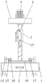
FIG. 1 is a schematic side sectional view of the present invention;
FIG. 2 is a schematic view of the installation front view structure of the threaded rod and the supporting frame of the present invention;
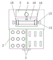
FIG. 3 is a schematic view of the sectional structure of the drawer and the storage groove;
fig. 4 is an enlarged schematic structural view of a portion a in fig. 1 according to the present invention.
In the figure: 1. a base; 2. a drawer; 3. a receiving groove; 4. a threaded rod; 5. a transverse plate; 6. a motor; 7. a support frame; 8. a limiting block; 9. a limiting rod; 10. mounting grooves; 11. connecting blocks; 12. a telescopic rod; 13. a hardness meter; 14. a support plate; 15. a guide bar; 16. a splint; 17. a slider; 18. a chute; 19. a work bench.
Detailed Description
The technical solutions in the embodiments of the present invention will be described clearly and completely with reference to the accompanying drawings in the embodiments of the present invention, and it is obvious that the described embodiments are only some embodiments of the present invention, not all embodiments. Based on the embodiments in the present invention, all other embodiments obtained by a person skilled in the art without creative work belong to the protection scope of the present invention.
Referring to fig. 1-4, the present invention provides a technical solution: a device for rapidly detecting the hardness of a casting product comprises a base 1, a drawer 2, an accommodating groove 3, a threaded rod 4, a transverse plate 5, a motor 6, a support frame 7, a limiting block 8, a limiting rod 9, a mounting groove 10, a connecting block 11, a telescopic rod 12, a hardness tester 13, a support plate 14, a guide rod 15, a clamping plate 16, a sliding block 17, a sliding groove 18 and a workbench 19, wherein the drawer 2 is arranged inside the base 1, the accommodating groove 3 is formed inside the drawer 2, the threaded rod 4 is arranged at the upper end of the base 1, the tail end of the threaded rod 4 is connected with the transverse plate 5, the motor 6 is arranged on the outer surface of the transverse plate 5, the output end of the motor 6 is connected with the threaded rod 4, the support frame 7 is arranged on the outer surface of the threaded rod 4, the limiting block 8 is arranged at the tail end of the, the connecting block 11 end is connected with telescopic link 12, and telescopic link 12 end-to-end installs sclerometer 13, and backup pad 14 is installed to base 1 upper end, and the backup pad 14 surface is provided with guide bar 15 to 15 end-to-end installations of guide bar have splint 16, and splint 16 lower extreme is provided with slider 17, and slider 17 is connected with spout 18, and spout 18 sets up inside workstation 19.
The containing grooves 3 are distributed at equal intervals in relation to the inside of the drawer 2, and the shapes of the containing grooves 3 are different, so that a user can place tools into the corresponding containing grooves 3 according to the shapes of the tools to contain workpieces, and the practicability of the device is improved.
The telescopic link 12 constitutes the block structure through connecting block 11 and mounting groove 10, and the length of connecting block 11 equals with the degree of depth of mounting groove 10, and the person of facilitating the use changes sclerometer 13 to the person of facilitating the use clears up and maintains the life who has improved sclerometer 13 to sclerometer 13.
The clamping plate 16 forms a sliding structure through the sliding block 17 and the sliding groove 18, and the transverse section of the sliding block 17 is of a circular structure, so that the movement of the clamping plate 16 is limited, the clamping plate 16 always keeps moving in the plane, and the safety of the device in use is guaranteed.
The surface symmetry of workstation 19 is provided with 2 splint 16, and splint 16 transverse section is the rectangle column structure, and splint 16 surface is provided with magnet, and the stability when multiplicable is fixed to the work piece improves the device's practicality.
The working principle is as follows: when the device for rapidly detecting the hardness of the casting product is used, firstly, a workpiece to be detected is placed above a workbench 19, secondly, the distance between clamping plates 16 is adjusted according to guide rods 15 on the outer surfaces of supporting plates 14, the sliding blocks 17 are driven to move inside sliding grooves 18 when the clamping plates 16 move, the clamping plates 16 are used for fixedly clamping the workpiece, then, the distance between a hardness tester 13 and a supporting frame 7 is adjusted according to a telescopic rod 12, the hardness tester 13 corresponds to the workpiece to be detected, then, a motor 6 on the upper end of a transverse plate 5 is started, the motor 6 drives a threaded rod 4 to rotate, the supporting frame 7 moves downwards when the threaded rod 4 rotates, the supporting frame 7 drives a limiting block 8 to move downwards on the outer surface of a limiting rod 9 when moving, until the hardness tester 13 and the workpiece reach a proper distance, and the hardness tester 13 is used for detecting the hardness;
when not using, can twist the bolt of 7 surfaces of support frame, take out connecting block 11 from mounting groove 10 inside, make sclerometer 13 and support frame 7 separation, the person of facilitating the use clears up and maintains sclerometer 13, thereby the person of facilitating the use clears up and maintains sclerometer 13, improve sclerometer 13's life, stimulate drawer 2 at last, make drawer 2 and base 1 separation, the user can place corresponding 3 insides of accomodating in the groove with the instrument, carry out categorised accomodating to the instrument, whole practicality has been increased.
Although embodiments of the present invention have been shown and described, it will be appreciated by those skilled in the art that changes, modifications, substitutions and alterations can be made in these embodiments without departing from the principles and spirit of the invention, the scope of which is defined in the appended claims and their equivalents.
Claims (6)
1. The utility model provides a device of short-term test foundry goods product hardness, includes base (1) and motor (6), its characterized in that: the novel multifunctional adjustable base is characterized in that a drawer (2) is arranged inside the base (1), a containing groove (3) is formed inside the drawer (2), a threaded rod (4) is arranged at the upper end of the base (1), the tail end of the threaded rod (4) is connected with a transverse plate (5), a motor (6) is arranged on the outer surface of the transverse plate (5), the output end of the motor (6) is connected with the threaded rod (4), a supporting frame (7) is arranged on the outer surface of the threaded rod (4), a limiting block (8) is arranged at the tail end of the supporting frame (7), the limiting block (8) is connected with a limiting rod (9), a mounting groove (10) is formed inside the supporting frame (7), a connecting block (11) is arranged inside the mounting groove (10), the tail end of the connecting block (11) is connected with a telescopic rod (12), a hardness tester (13, and the surface of the supporting plate (14) is provided with a guide rod (15), the tail end of the guide rod (15) is provided with a clamping plate (16), the lower end of the clamping plate (16) is provided with a sliding block (17), the sliding block (17) is connected with a sliding groove (18), and the sliding groove (18) is arranged inside a workbench (19).
2. The apparatus of claim 1 for rapid hardness testing of cast products, wherein: the receiving grooves (3) are equally spaced with respect to the inside of the drawer (2), and there is a difference in shape between the receiving grooves (3).
3. The apparatus of claim 1 for rapid hardness testing of cast products, wherein: the support frame (7) forms a sliding structure with the limiting rod (9) through the limiting block (8), and the support frame (7) is in threaded connection with the threaded rod (4).
4. The apparatus of claim 1 for rapid hardness testing of cast products, wherein: the telescopic rod (12) and the mounting groove (10) form a clamping structure through the connecting block (11), and the length of the connecting block (11) is equal to the depth of the mounting groove (10).
5. The apparatus of claim 1 for rapid hardness testing of cast products, wherein: the clamping plate (16) forms a sliding structure through the sliding block (17) and the sliding groove (18), and the transverse section of the sliding block (17) is of a circular structure.
6. The apparatus of claim 1 for rapid hardness testing of cast products, wherein: the outer surface symmetry of workstation (19) is provided with 2 splint (16), and splint (16) horizontal cross-section is rectangular structure.
Priority Applications (1)
| Application Number | Priority Date | Filing Date | Title |
|---|---|---|---|
| CN202020953505.0U CN212228562U (en) | 2020-05-30 | 2020-05-30 | Device for rapidly detecting hardness of casting product |
Applications Claiming Priority (1)
| Application Number | Priority Date | Filing Date | Title |
|---|---|---|---|
| CN202020953505.0U CN212228562U (en) | 2020-05-30 | 2020-05-30 | Device for rapidly detecting hardness of casting product |
Publications (1)
| Publication Number | Publication Date |
|---|---|
| CN212228562U true CN212228562U (en) | 2020-12-25 |
Family
ID=73931330
Family Applications (1)
| Application Number | Title | Priority Date | Filing Date |
|---|---|---|---|
| CN202020953505.0U Active CN212228562U (en) | 2020-05-30 | 2020-05-30 | Device for rapidly detecting hardness of casting product |
Country Status (1)
| Country | Link |
|---|---|
| CN (1) | CN212228562U (en) |
-
2020
- 2020-05-30 CN CN202020953505.0U patent/CN212228562U/en active Active
Similar Documents
| Publication | Publication Date | Title |
|---|---|---|
| CN103639778A (en) | Positioning tool for milling | |
| CN212228562U (en) | Device for rapidly detecting hardness of casting product | |
| CN218629356U (en) | Chain strength detection device | |
| CN211954691U (en) | Automobile vibration test bench capable of achieving multi-angle vibration test | |
| CN214952612U (en) | Aluminum alloy section tensile experiment clamp containing trace elements | |
| CN211122338U (en) | Intensity detection device is used in aluminum plate production | |
| CN113601429A (en) | Tool clamp capable of limiting at multiple angles for processing PCBA (printed circuit board assembly) board | |
| CN219065457U (en) | Fixing mechanism of metal material detection equipment | |
| CN220543084U (en) | Power supply box testing device | |
| CN218461572U (en) | Clamping mechanism for special-shaped steel member machining equipment | |
| CN219053379U (en) | Welding frock clamp with adjustable | |
| CN212658214U (en) | Projector workpiece clamping device for workpiece detection | |
| CN219346003U (en) | Camera module support | |
| CN202952081U (en) | Combined fixture for drilling machine | |
| CN219704250U (en) | Electric motor car frame processing mounting fixture | |
| CN215478280U (en) | CCD visual detection positioning and vacuum suction mechanism with good stability | |
| CN220380916U (en) | Pressure testing device | |
| CN216227404U (en) | Clamping device for electric corrosion electrode | |
| CN210773751U (en) | Automobile water tank lower cross beam gauge capable of reducing accumulated errors | |
| CN215413679U (en) | Mould accessory straightness detection device that hangs down | |
| CN218341553U (en) | Even internal stay formula foundry goods location frock of atress | |
| CN219811021U (en) | Motor maintenance detection device | |
| CN219914373U (en) | Application device for automatically detecting shaft diameter of workpiece | |
| CN220372862U (en) | Deckle edge grinding device | |
| CN218121267U (en) | Motor end cover casting quality detection tool |
Legal Events
| Date | Code | Title | Description |
|---|---|---|---|
| GR01 | Patent grant | ||
| GR01 | Patent grant |