SUMMERY OF THE UTILITY MODEL
The utility model provides a workpiece fixing device for simplify the operating procedure of fixed work piece, thereby reduce the lathe latency that the lathe caused because of fixed work piece operation difficulty.
The utility model provides a workpiece fixing device, include:
a base fixed on the worktable;
the rotary pressing mechanism is arranged on the base and is in rotary connection with the base; and
the driving mechanism is arranged on the base and is used for driving the rotating pressing mechanism to rotate towards the direction close to or far away from the workpiece;
when the rotating pressing mechanism rotates towards the direction close to the workpiece, the rotating pressing mechanism converts the driving force of the driving mechanism into pressing force on the workpiece so as to press the workpiece on the workbench.
In one embodiment, the rotary pressing mechanism includes:
a lever bracket fixedly disposed on the base; and
the lever pressing block is rotationally connected with the lever bracket;
the driving mechanism drives the first end of the lever pressing block to rotate towards the direction close to the workpiece, so that the first end of the lever pressing block is pressed onto the workpiece to apply pressing force to the workpiece.
In one embodiment, the driving mechanism includes a wedging block movably disposed on the base, and when the wedging block moves in a direction close to the lever pressing block, the wedging block extends below the second end of the lever pressing block, so that the second end of the lever pressing block is lifted and the first end of the lever pressing block is pressed onto the workpiece.
In one embodiment, the upper surface of the wedge block is configured as an inclined surface.
In one embodiment, the first end and the second end of the lever press are each configured as an arcuate end, and the first end of the lever press is smaller in size than the second end of the lever press.
In one embodiment, a horizontal section and an inclined section which are connected are arranged between the first end and the second end of the lever pressing block; the horizontal section is rotationally connected with the lever bracket through a pin; the inclined section is inclined toward a direction close to the base.
In one embodiment, the driving mechanism further comprises a pushing rod connected with the wedging block, and the pushing rod is used for pushing the wedging block to move towards the direction close to or away from the rotating pressing mechanism.
In one embodiment, one end of the wedging block, which is far away from the lever pressing block, is provided with a first threaded hole, and the pushing rod is in threaded connection with the first threaded hole.
In one embodiment, a support plate is arranged on the base, a second threaded hole is formed in the support plate, and the push rod penetrates through the second threaded hole and then extends into the first threaded hole.
In one embodiment, the operating end of the push rod is provided with a rotation handle.
Compared with the prior art, the utility model has the advantages of, rotate hold-down mechanism through the actuating mechanism drive and rotate towards the direction that is close to the work piece, then can compress tightly the work piece that is located on the workstation, consequently the utility model discloses a purpose of fixed work piece is reached to the driven mode of utilization to the operating procedure of current fixed work piece has been simplified greatly, the problem of the unable operation that traditional pressure sign indicating number mode appears can not appear more can not appear, can reduce the latency of lathe, improve machining efficiency.
Detailed Description
The present invention will be further explained with reference to the accompanying drawings.
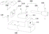
As shown in fig. 1-5, the present invention provides a workpiece fixture 500 for quickly fixing a machined workpiece. Specifically, the workpiece fixing device 500 of the present invention includes a base 100, and a rotating pressing mechanism 200 and a driving mechanism 300 respectively disposed on the base 100. Wherein, the base 100 is fixed on the worktable 101, and one side of the base 100 is attached to one side of the workpiece 102. The rotary pressing mechanism 200 is rotatably connected to the base 100, and the driving mechanism 300 is used for driving the rotary pressing mechanism 200 to rotate toward or away from the workpiece 102. When the rotary pressing mechanism 200 is rotated in a direction to approach the workpiece 102, the rotary pressing mechanism 200 converts the driving force of the driving mechanism 300 into a pressing force to press the workpiece 102 placed on the table 101 against the table 101.
In one particular embodiment, as shown in fig. 1 and 2, the pivoting hold-down mechanism 200 includes a lever bracket 210 and a lever press 220. Wherein the lever bracket 210 is fixedly provided on the base 100. The lever pressing block 220 is rotatably connected to the lever bracket 210. The first end of the lever pressing piece 220 can be driven by the driving mechanism 300 to rotate towards the direction close to the workpiece 102, so that the first end (i.e. the end B shown in fig. 1) of the lever pressing piece 220 is pressed onto the workpiece 102 to apply pressing force to the workpiece 102. Specifically, a first end (i.e., end B shown in fig. 1) of the lever press 220 presses against the upper surface of the workpiece 102.
As shown in fig. 2, the driving mechanism 300 includes a wedge block 310 movably disposed on the base 100, and when the wedge block 310 moves in a direction approaching the lever pressing block 220, the wedge block 310 extends below the second end (i.e., the end B shown in fig. 1) of the lever pressing block 220, so that the second end (i.e., the end B shown in fig. 1) of the lever pressing block 220 is lifted and the first end (i.e., the end B shown in fig. 1) thereof is pressed onto the upper surface of the workpiece 102.
As shown in fig. 1, showing the wedge block 310 extended below the second end of the lever pressing piece 220, the upper surface S of the wedge block 310 is configured as an inclined surface so that the wedge block 310 can be more easily extended below the second end of the lever pressing piece 220. During the moving process of the wedge block 310, as the wedge block 310 gets closer to the lever pressing block 220, the upper surface S thereof gets deeper below the second end of the lever pressing block 220, so as to lift the second end of the lever pressing block 220 higher; meanwhile, since the lever pressing block 220 is rotatably connected to the lever bracket 210, when the second end of the lever pressing block 220 is lifted, the first end (i.e., the end B shown in fig. 1) thereof moves toward the workpiece 102, i.e., the first end is pressed down, and if the second end of the lever pressing block 220 is lifted higher, the first end thereof is pressed down lower, so that the first end of the lever pressing block 220 is pressed against the upper surface of the workpiece 102, thereby fixing the workpiece 102 on the worktable 101.
Therefore, the workpiece fixing device 500 of the present invention achieves the purpose of fixing the workpiece 102 by using the force transmission mode, thereby greatly simplifying the operation steps; the problem that the traditional code pressing mode cannot be operated can be solved, so that the waiting time of the machine tool is shortened, and the machining efficiency is improved.
In some preferred embodiments, the first and second ends of the lever press 220 are each configured as arcuate ends. Since the second end of the lever pressing block 220 is the end contacting with the upper surface S of the wedging block 310, the second end of the lever pressing block 220 is configured as an arc-shaped end, which can facilitate the wedging block 310 to extend into the second end (end a) of the lever pressing block 220, and can avoid the phenomenon that the second end (end a) of the lever pressing block 220 cannot be lifted due to the wedging block 310 and the lever pressing block 220 being stuck.
In addition, since the first end (B end) of the lever pressing block 220 is the end in contact with the upper surface of the workpiece 102, the first end (B end) of the lever pressing block 220 is configured as an arc-shaped end, so that the lever pressing block 220 can form a line contact with the upper surface of the workpiece 102, and can be adapted to workpieces 102 with various heights, and the phenomenon that the workpiece 102 cannot be pressed with the surface of the workpiece 102 when the height of the workpiece 102 is high can be avoided.
Further, as shown in fig. 4, a horizontal section 221 and an inclined section 222 are provided between the first end (B end) and the second end (a end) of the lever pressing block 220 to be connected. It is understood that the lever pressing block 220 is connected to the lever bracket 210 by the pin 230 in a lever structure that is rotatably moved about the pin 230.
Wherein, the horizontal section 221 is rotatably connected with the lever bracket 210 through a pin 230; the inclined section 222 is inclined toward the direction close to the base 100. The provision of the inclined section 222 enables the lever press piece 220 to be adapted to workpieces 102 of different heights and to press the workpieces 102 more tightly against the table 101.
Furthermore, the size of the first end (B end) of the lever pressing block 220 is smaller than that of the second end (a end) thereof, and the second end (a end) of the lever pressing block 220 is heavier, so that when the wedge block 310 leaves the second end (a end) of the lever pressing block 220, the second end (a end) of the lever pressing block 220 can naturally lift up due to the loss of support and the heavier weight thereof, and can leave the workpiece 102 without manually separating from the workpiece 102.
So that when the workpiece 102 is not fixed by the lever pressing block 220 (as shown in fig. 3), the horizontal section 221 of the lever pressing block is kept parallel to the upper surface of the base 100, i.e. the lever pressing block 220 is kept at a balanced position,
the lever bracket 210 and the base 100 can be customized to match the size according to the thickness range and specific production requirement of the daily processed workpiece 102, and the present invention is not limited thereto. And the base 100 and the lever bracket 210 simultaneously determine the height of the workpiece 102 that can be fixed by the workpiece fixing device 500 of the present invention, thereby widening the application range thereof.
In one specific embodiment, the driving mechanism 300 further comprises a push rod 320 connected to the wedge block 310, the push rod 320 being used to push the wedge block 310 toward or away from the rotational pressing mechanism 200.
The wedge 310 can be maintained in a semi-free state movable in parallel with the base 100 by the push rod 320. As shown in fig. 3, one end of the wedge block 310 away from the lever pressing block 220 is provided with a first threaded hole 311, and the push rod 320 is in threaded connection with the first threaded hole 311. The wedge block 310 can be pushed to move toward or away from the lever pressing block 220 by screwing the push rod 320 into the first threaded hole 311 or screwing the push rod 320 out of the first threaded hole 311.
In addition, a support plate 110 is arranged on the base 100, a second threaded hole 111 is arranged on the support plate 110, and the push rod 320 passes through the second threaded hole 111 and then extends into the first threaded hole 311. Since the pushing rod 320 is also in threaded connection with the second threaded hole 111, when the pushing rod 320 pushes the wedge block 310 to a suitable position where the first end (B end) of the lever pressing block 220 can press the workpiece 102 against the worktable 101, the pushing rod 320 can be prevented from backing out of the wedge block 310 by the second threaded hole 111, and thus the pushing rod 320 can be fixed at a desired position by the threaded connection of the pushing rod 320 with the second threaded hole 111.
When the workpiece 102 is fixed, the pushing rod 320 is manually rotated by an operator to drive the wedging block 310 to move towards the direction close to the lever pressing block 220, and the force of manually rotating the pushing rod 320 is converted into the force of pressing the workpiece 102 by the lever pressing block 220 in an approximate transmission mode, so that a series of problems caused by manual fixation of each component by a screw and complicated operation in the conventional pressing method are thoroughly solved, and the efficiency of fixing the workpiece 102 in actual production is greatly improved.
The utility model discloses a work piece fixing device 500, its impulse rod 320 is threaded connection with extension board 110 and wedging piece 310, and lever briquetting 220 is then pin joint with being connected of lever bracket 210, and the flexibility and the detachability of its use are higher consequently to the maintenance and the change after its wearing and tearing or damage have been made things convenient for greatly. And each part is closely matched, and when the device is not needed to be used, each part is stored and is relatively fixed, so that the problem of inconvenient field management caused by dispersion of each part in the traditional method is solved.
Further, the operating end of the push lever 320 is provided with a rotation handle 330. As shown in fig. 2, the axis of the rotation handle 330 is perpendicular to the axis of the push rod 320, and the operator can conveniently rotate the push rod 320 by rotating the rotation handle 330.
It will be appreciated that the push rod 320 may be replaced with an automated component such as a hydraulic rod, such that rotation of the lever press 220 may be accomplished through an automated process.
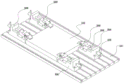
As shown in fig. 2, a plurality of connection holes are formed in the base 100, and the base 110 is fixedly connected to the table 101 by fasteners 120 in the connection holes.
In the in-service use in-process, the operator can judge by oneself according to the size of actual work piece 102 the utility model discloses a work piece fixing device 500's use quantity and position (as shown in fig. 5, be provided with 4 work piece fixing device 500 on the workstation 101), contrast traditional pressure sign indicating number mode, the utility model discloses a work piece fixing device 500 has also improved its flexibility when having guaranteed easy and simple to handle nature, provides a more simple convenient method for fixed work piece 102, has also improved machining efficiency indirectly.
The utility model discloses a work piece fixing device 500, its application method is as follows:
first, the base 100 is fixed to the table 101, and the lever pressing piece 220 is rotatably coupled to the lever bracket 210 by the pin 230.
Next, the push rod 320 is rotated such that the end thereof passes through the second screw hole 111 and then extends into the first screw hole 311 of the wedge block 310. The pushing rod 320 is further tightened to push the wedge 310 to move on the base 100 toward the lever pressing block 220.
Thirdly, when the wedging block 310 touches the second end (end a) of the lever pressing block 220, the wedging block 310 is continuously pushed to move, the upper surface S of the wedging block 310 extends below the second end (end a) of the lever pressing block 220, so as to lift the second end (end a) of the lever pressing block 220, and as the wedging block 310 gets closer to the lever pressing block 220, the higher the second end (end a) of the lever pressing block 220 is lifted, the lower the first end (end B) thereof is pressed, so that the workpiece 102 can be fixed on the worktable 101.
Finally, after the machining is completed, the pushing rod 320 is rotated in the reverse direction, so that the pushing rod can be screwed out of the wedging block 310, the second end (end a) of the lever pressing block 220 is unsupported and falls, and the first end (end B) of the lever pressing block is naturally lifted, so that the workpiece 102 and the workbench 101 are unlocked.
While the invention has been described with reference to a preferred embodiment, various modifications may be made and equivalents may be substituted for elements thereof without departing from the scope of the invention. In particular, the technical features mentioned in the embodiments can be combined in any way as long as there is no structural conflict. The present invention is not limited to the particular embodiments disclosed herein, but encompasses all technical solutions falling within the scope of the claims.