CN212202551U - Direct current cooling fan - Google Patents
Direct current cooling fan Download PDFInfo
- Publication number
- CN212202551U CN212202551U CN202020809667.7U CN202020809667U CN212202551U CN 212202551 U CN212202551 U CN 212202551U CN 202020809667 U CN202020809667 U CN 202020809667U CN 212202551 U CN212202551 U CN 212202551U
- Authority
- CN
- China
- Prior art keywords
- fan
- groove
- connecting plate
- push block
- plate
- Prior art date
- Legal status (The legal status is an assumption and is not a legal conclusion. Google has not performed a legal analysis and makes no representation as to the accuracy of the status listed.)
- Active
Links
Images


Landscapes
- Cooling Or The Like Of Electrical Apparatus (AREA)
- Structures Of Non-Positive Displacement Pumps (AREA)
Abstract
The utility model discloses a direct current radiator fan relates to heat-radiating equipment technical field, including first fan board, second fan board and connecting plate, its characterized in that: the first fan plate is rotatably connected to the left side of the connecting plate; has the advantages that: the first switch and the second switch are respectively controlled, the number of working heat dissipation fans can be adjusted according to requirements, the first fan plate and the second fan plate are respectively connected with the connecting plate through hinges, and the supporting rods are supported, so that the using state can be switched, and the using requirements can be better met; the first sliding strip and the second sliding strip are arranged to slidably support, the friction of the first supporting spring and the second supporting spring is increased, the first sliding strip and the second sliding strip are locked, and the using state of the first fan board and the second fan board can be guaranteed.
Description
Technical Field
The utility model relates to a heat-radiating equipment technical field especially relates to a direct current radiator fan.
Background
As is known, the arrangement of a dc heat dissipation fan is intended to solve the heat dissipation problem of computers, refrigerators, printers, air evolvers, and other living electrical appliances, and the role of the heat dissipation fan in industrial manufacturing is still really small, and the proportion of the heat dissipation fan used in industry is far greater than that of the living electrical appliances according to incomplete statistics.
At present, direct current cooling fans on the market are simple in structure, generally fixedly installed, single in function and use and incapable of well meeting use requirements of people.
SUMMERY OF THE UTILITY MODEL
An object of the present invention is to provide a direct current cooling fan for solving the above problems.
The utility model discloses a following technical scheme realizes above-mentioned purpose:
the utility model provides a direct current radiator fan, includes first fan plate, first direct current radiator fan, first switch, first recess, first ejector pad, connecting plate, the battery, the second ejector pad, second fan plate, second direct current radiator fan, the second recess, the second switch, first spout, first movable groove, first supporting spring, first draw runner, first slot, supporting groove, accomodate the groove, the bracing piece, the second spout, the second draw runner, second supporting spring, second movable groove and second slot, its characterized in that: the left side of the connecting plate is rotatably connected with the first fan plate, the middle of the upper surface of the first fan plate is provided with the first groove, the first switch is fixedly installed in the first groove, the front part and the rear part of the first groove are respectively provided with the first direct-current radiating fan, and the middle of the lower surface of the first fan plate is provided with the supporting groove; the right side of the connecting plate is rotatably connected with the second fan plate, the middle of the upper surface of the second fan plate is provided with the second groove, the second switch is fixedly installed in the second groove, and the front part and the rear part of the second groove are respectively provided with the second direct-current cooling fan; the storage battery is arranged in the connecting plate, the accommodating groove is arranged in the middle of the lower surface of the connecting plate, the supporting rod is arranged in the accommodating groove, the right end of the supporting rod is rotatably connected with the connecting plate, the first sliding groove is arranged on the left side of the front end and the rear end of the connecting plate, the first sliding strip is arranged in the first sliding groove, the first sliding strip slides in the first sliding groove, the first movable groove is arranged on the first sliding strip, the first push block and the first support spring are arranged in the first movable groove, the two ends of the first support spring are respectively fixedly connected with the first sliding strip and the first push block, the first push block extends out of the connecting plate, the two ends of the connecting plate are provided with openings corresponding to the first push block, and part of the first push block, which is positioned in the connecting plate, is clamped in the corresponding openings of the connecting plate to move, the first fan plate is provided with the first slot corresponding to the first sliding strip, the right sides of the front end and the rear end of the connecting plate are provided with the second sliding groove, the second sliding strip is arranged in the second sliding groove, the second sliding strip slides in the second sliding groove, the second sliding strip is provided with the second movable groove, the second movable groove is internally provided with the second push block and the second support spring, two ends of the second support spring are respectively fixedly connected with the second sliding strip and the second push block, the second push block extends out of the connecting plate, two ends of the connecting plate are provided with openings corresponding to the second push block, part of the second push block, which is positioned in the connecting plate, is clamped in the corresponding openings of the connecting plate to move, and the second fan plate is provided with the second slot corresponding to the second sliding strip; the first switch and the second switch are electrically connected with the storage battery respectively, the first direct current cooling fan is electrically connected with the first switch, and the second direct current cooling fan is electrically connected with the second switch.
Preferably, the first direct current cooling fan and the second direct current cooling fan both include an upper filter screen, a lower filter screen, a support frame, a motor, and a fan blade.
Preferably, the lower edge of the right side of the first fan plate is connected with the lower edge of the left side of the connecting plate through a hinge, and the lower edge of the left side of the second fan plate is connected with the lower edge of the right side of the connecting plate through a hinge.
Preferably, teeth are arranged in the supporting groove.
Preferably, one end of the first sliding strip, which is close to the first fan plate, is set to be a round head, and one end of the second sliding strip, which is close to the second fan plate, is set to be a round head.
Preferably, the surfaces of the first push block and the second push block are provided with convex strips.
Has the advantages that: the first switch and the second switch are respectively controlled, the number of working heat dissipation fans can be adjusted according to requirements, the first fan plate and the second fan plate are respectively connected with the connecting plate through hinges, and the supporting rods are supported, so that the using state can be switched, and the using requirements can be better met; the first sliding strip and the second sliding strip are arranged for sliding support, and the first supporting spring and the second supporting spring increase friction, so that the first sliding strip and the second sliding strip are locked, and the use states of the first fan plate and the second fan plate can be guaranteed; the direct current fan can be used for removing summer heat by folding the first fan plate and connecting the second fan plate.
Drawings
In order to more clearly illustrate the embodiments of the present invention or the technical solutions in the prior art, the drawings needed to be used in the description of the embodiments or the prior art will be briefly described below, it is obvious that the drawings in the following description are only some embodiments of the present invention, and for those skilled in the art, other drawings can be obtained according to these drawings without inventive exercise.
Fig. 1 is a schematic top view of a direct current heat dissipation fan according to the present invention.
Fig. 2 is a front view of the dc heat dissipation fan of the present invention.
Fig. 3 is a bottom view of the dc heat dissipation fan of the present invention.
Fig. 4 is a sectional view of a-a of a dc heat dissipation fan according to the present invention.
Fig. 5 is an enlarged view of a position B of the dc heat dissipation fan according to the present invention.
Fig. 6 is an enlarged view of the position C of the dc heat dissipation fan of the present invention.
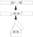
Fig. 7 is a schematic diagram of a dc heat dissipation fan according to the present invention.
The reference numerals are explained below:
1. a first fan plate; 2. a first direct current heat radiation fan; 3. a first switch; 4. a first groove; 5. a first push block; 6. a connecting plate; 7. a storage battery; 8. a second push block; 9. a second fan plate; 10. a second direct current heat radiation fan; 11. a second groove; 12. a second switch; 13. a first chute; 14. a first movable slot; 15. a first support spring; 16. a first slide bar; 17. a first slot; 18. a support groove; 19. a receiving groove; 20. a support bar; 21. a second chute; 23. a second slide bar; 24. a second support spring; 25. a second movable slot; 26. a second slot.
Detailed Description
In the description of the present invention, it is to be understood that the terms "central", "longitudinal", "lateral", "upper", "lower", "front", "rear", "left", "right", "vertical", "horizontal", "top", "bottom", "inner", "outer", etc., indicate orientations or positional relationships based on those shown in the drawings, and are used only for convenience in describing and simplifying the description, but not for indicating or implying that the device or element being referred to must have a particular orientation, be constructed and operated in a particular orientation, and thus are not to be construed as limiting the invention, and further that the terms "first", "second", etc., are used only for descriptive purposes and are not to indicate or imply relative importance or imply the number of technical features being referred to, whereby the features defined as "first", "second", etc., may explicitly or implicitly include one or more such features, in the description of the present invention, "a plurality" means two or more unless otherwise specified.
In the description of the present invention, it is to be noted that, unless otherwise explicitly specified or limited, the terms "mounted," "connected," and "connected" are to be construed broadly, and may be, for example, fixedly connected, detachably connected, or integrally connected; can be mechanically or electrically connected; the two elements may be directly connected or indirectly connected through an intermediate medium, or the two elements may be connected through an intermediate medium, and the specific meaning of the above terms in the present invention can be understood by those skilled in the art through specific situations.
The technical scheme of the invention is further explained below with the accompanying drawings:
as shown in fig. 1 to 7, a direct current heat dissipation fan includes a first fan plate 1, a first direct current heat dissipation fan 2, a first switch 3, a first groove 4, a first push block 5, a connecting plate 6, a battery 7, a second push block 8, a second fan plate 9, a second direct current heat dissipation fan 10, a second groove 11, a second switch 12, a first sliding groove 13, a first movable groove 14, a first support spring 15, a first sliding bar 16, a first slot 17, a support groove 18, a storage groove 19, a support rod 20, a second sliding groove 21, a second sliding bar 23, a second support spring 24, a second movable groove 25, and a second slot 26, and is characterized in that: the left side of the connecting plate 6 is rotatably connected with a first fan plate 1, the first fan plate 1 is used for connection, a first groove 4 is formed in the middle of the upper surface of the first fan plate 1, a first switch 3 is fixedly installed in the first groove 4, the first switch 3 is arranged in the first groove 4, the situation that the first switch 3 is higher than the surface of the first fan plate 1 and is touched by mistake is avoided, first direct-current heat dissipation fans 2 are respectively arranged in the front and at the back of the first groove 4, the first direct-current heat dissipation fans 2 are used for blowing, a supporting groove 18 is formed in the middle of the lower surface of the first fan plate 1, and the supporting groove 18 is used for facilitating supporting; a second fan plate 9 is rotatably connected to the right side of the connecting plate 6, the second fan plate 9 is used for connection, a second groove 11 is formed in the middle of the upper surface of the second fan plate 9, the second groove 11 is used for convenient support, a second switch 12 is fixedly installed in the second groove 11, the second switch 12 is arranged in the second groove 11, the situation that the second switch 12 is higher than the surface of the second fan plate 9 and is touched by mistake is avoided, second direct-current heat dissipation fans 10 are respectively arranged in front of and behind the second groove 11, and the second direct-current heat dissipation fans 10 are used for blowing air; the connecting plate 6 is internally provided with a storage battery 7, the storage battery 7 is used for supplying power, the middle of the lower surface of the connecting plate 6 is provided with a containing groove 19, the containing groove 19 is used for containing, the inside of the containing groove 19 is provided with a support rod 20, the support rod 20 is used for supporting, the right end of the support rod 20 is rotatably connected with the connecting plate 6, the left sides of the front end and the rear end of the connecting plate 6 are provided with a first sliding groove 13, the first sliding groove 13 is used for sliding, a first sliding strip 16 is arranged in the first sliding groove 13, the first sliding strip 16 is used for limiting rotation, the first sliding strip 16 slides in the first sliding groove 13, the first sliding strip 16 is provided with a first movable groove 14, the first movable groove 14 is used for moving, the first movable groove 14 is internally provided with a first push block 5 and a first supporting spring 15, the first push block 5 is used for pushing and pulling, the first supporting spring 15 is used for supporting and resetting, the two ends of the, the first push block 5 extends out of the connecting plate 6, two ends of the connecting plate 6 are provided with openings corresponding to the first push block 5, the part of the first push block 5 positioned in the connecting plate 6 is clamped in the opening corresponding to the connecting plate 6 to move, the first fan plate 1 is provided with a first slot 17 corresponding to the first slide bar 16, the first slot 17 is used for convenient insertion, the right sides of the front end and the rear end of the connecting plate 6 are provided with a second slide groove 21, the second slide groove 21 is used for sliding, the second slide bar 23 is arranged in the second slide groove 21, the second slide bar 23 is used for limiting rotation, the second slide bar 23 slides in the second slide groove 21, the second slide bar 23 is provided with a second movable groove 25, the second movable groove 25 is used for limiting movement, the second push block 8 and a second support spring 24 are arranged in the second movable groove 25, the second push block 8 is used for push-pull, the second support spring 24 is used for supporting and resetting, two ends of the second support spring 24 are respectively fixedly connected with the second slide bar 23 and the second push block, the second push block 8 extends out of the connecting plate 6, openings are formed in two ends of the connecting plate 6 corresponding to the second push block 8, the part, located in the connecting plate 6, of the second push block 8 is clamped in the corresponding opening of the connecting plate 6 to move, a second fan plate 9 is provided with a second slot 26 corresponding to the second sliding strip 23, and the second slot 26 is used for being conveniently inserted; the first switch 3 and the second switch 12 are respectively electrically connected with the storage battery 7, the first direct current cooling fan 2 is electrically connected with the first switch 3, and the second direct current cooling fan 10 is electrically connected with the second switch 12; the first direct current cooling fan 2 and the second direct current cooling fan 10 both comprise an upper filter screen, a lower filter screen, a support frame, a motor and fan blades; a lower filter screen is arranged below the support frame and used for filtering, a motor is fixedly arranged on the support frame and used for driving, fan blades are fixedly arranged on the output end of the motor and used for blowing, an upper filter screen is arranged above the fan blades and used for protecting and avoiding touching the fan blades, the lower edge of the right side of the first fan plate 1 is connected with the lower edge of the left side of the connecting plate 6 through a hinge, and the upper edge of the left side of the second fan plate 9 is connected with the upper edge of the right side of the connecting plate 6 through a hinge; teeth are arranged in the supporting groove 18, so that the supporting plate is convenient to support; first draw runner 16 is close to 1 one end of first fan board and sets up to the button head, and the first draw runner 16 of being convenient for inserts first slot 17 in, and second draw runner 23 is close to 9 one ends of second fan board and sets up to the button head, and the second draw runner 23 of being convenient for inserts second slot 26 in, and first ejector pad 5 and 8 surfaces of second ejector pad all are equipped with the sand grip, increase contact friction.
The working principle is as follows: when the direct-current cooling fan is used, the storage battery 7 is electrified, the first direct-current cooling fan 2 or the second direct-current cooling fan 10 is started according to the requirement under the control of the first switch 3 and the second switch 12, when the first direct-current cooling fan 2 and the second direct-current cooling fan 10 are required to work simultaneously, the first push block 5 is pressed, the first supporting spring 15 is compressed, the contact surface of the first push block 5 and the first sliding groove 13 is separated, the first push block 5 is pushed, the first sliding strip 16 is pushed into the first slot 17, the first push block 5 is released, the first supporting spring 15 is supported, the first push block 5 and the first sliding groove 13 are contacted to increase friction, the movement of the first push block 5 is reduced, and similarly, the second push block 8 is pressed, the second supporting spring 24 is compressed, the contact surface of the second push block 8 and the second sliding groove 21 is separated, the second push block 8 is pushed, the second sliding strip 23 is pushed into the second slot 26, the second push block 8 is released, and the second supporting spring 24 is supported, the second pushing block 8 is in contact with the second sliding groove 21 to increase friction, so that the movement of the second pushing block 8 is reduced, the first fan plate 1 and the connecting plate 6 are connected and limited to rotate through the support of the first sliding strip 16, and the second fan plate 9 and the connecting plate 6 are connected and limited to rotate through the support of the second sliding strip 23, so that the first fan plate 1, the connecting plate 6 and the second fan plate 9 are fixed in an unfolded state, and the first direct-current cooling fan 2 and the second direct-current cooling fan 10 can work simultaneously to improve the cooling efficiency; when heat dissipation is not needed, the first push block 5 can be pressed, the first supporting spring 15 is compressed, the contact surface of the first push block 5 and the first sliding groove 13 is separated, the first push block 5 is pulled back, the first sliding strip 16 is pulled back into the first sliding groove 13, the first push block 5 is released, the first supporting spring 15 is supported, the first push block 5 and the first sliding groove 13 are contacted to increase friction, the movement of the first push block 5 is reduced, similarly, the second push block 8 is pressed, the second supporting spring 24 is compressed, the contact surface of the second push block 8 and the second sliding groove 21 is separated, the second push block 8 is pulled back, the second sliding strip 23 is pulled back into the second sliding groove 21, the second push block 8 is released, the second supporting spring 24 is supported, the second push block 8 and the second sliding groove 21 are contacted to increase friction, the movement of the second push block 8 is reduced, the second fan board 9 can be folded, the connecting board 6 is in the middle, the first fan board 1 is supported by the supporting rod 20 and is supported in the supporting groove 18, the first fan plate 1 is obliquely arranged, the first switch 3 is turned on, and the first direct current heat dissipation fan 2 works to become a direct current fan which can help to blow and remove summer heat.
The foregoing illustrates and describes the principles, general features, and advantages of the present invention. It will be understood by those skilled in the art that the present invention is not limited to the above embodiments, and that the foregoing embodiments and descriptions are provided only to illustrate the principles of the present invention without departing from the spirit and scope of the present invention.
Claims (6)
1. The utility model provides a direct current radiator fan, includes first fan board (1), first direct current radiator fan (2), first switch (3), first recess (4), first ejector pad (5), connecting plate (6), battery (7), second ejector pad (8), second fan board (9), second direct current radiator fan (10), second recess (11), second switch (12), first spout (13), first activity groove (14), first supporting spring (15), first draw runner (16), first slot (17), supporting groove (18), accomodate groove (19), bracing piece (20), second spout (21), second draw runner (23), second supporting spring (24), second activity groove (25) and second slot (26), its characterized in that: the left side of the connecting plate (6) is rotatably connected with the first fan plate (1), the first groove (4) is formed in the middle of the upper surface of the first fan plate (1), the first switch (3) is fixedly installed in the first groove (4), the front and the back of the first groove (4) are respectively provided with the first direct-current heat dissipation fan (2), and the middle of the lower surface of the first fan plate (1) is provided with the supporting groove (18); the second fan plate (9) is rotatably connected to the right side of the connecting plate (6), the second groove (11) is formed in the middle of the upper surface of the second fan plate (9), the second switch (12) is fixedly installed in the second groove (11), and the second direct-current heat dissipation fans (10) are respectively arranged in the front and at the back of the second groove (11); the storage battery (7) is arranged in the connecting plate (6), the accommodating groove (19) is arranged in the middle of the lower surface of the connecting plate (6), the supporting rod (20) is arranged in the accommodating groove (19), the right end of the supporting rod (20) is rotatably connected with the connecting plate (6), the first sliding groove (13) is arranged on the left side of the front end and the rear end of the connecting plate (6), the first sliding strip (16) is arranged in the first sliding groove (13), the first sliding strip (16) slides in the first sliding groove (13), the first movable groove (14) is arranged on the first sliding strip (16), the first push block (5) and the first support spring (15) are arranged in the first movable groove (14), two ends of the first support spring (15) are respectively and fixedly connected with the first sliding strip (16) and the first push block (5), the first push block (5) extends out of the connecting plate (6), openings are formed in two ends of the connecting plate (6) corresponding to the first push block (5), the portion, located in the connecting plate (6), of the first push block (5) is clamped in the corresponding openings of the connecting plate (6) to move, the first fan plate (1) is provided with the first slot (17) corresponding to the first sliding strip (16), the second sliding groove (21) is formed in the right sides of the front end and the rear end of the connecting plate (6), the second sliding strip (23) is arranged in the second sliding groove (21), the second sliding strip (23) slides in the second sliding groove (21), the second movable groove (25) is formed in the second sliding strip (23), the second push block (8) and the second support spring (24) are arranged in the second movable groove (25), and two ends of the second support spring (24) are respectively connected with the second sliding strip (23) and the second push block (5) 8) The second push block (8) extends out of the connecting plate (6), openings are formed in two ends of the connecting plate (6) corresponding to the second push block (8), the part, located in the connecting plate (6), of the second push block (8) is clamped in the corresponding openings of the connecting plate (6) to move, and the second fan plate (9) is provided with a second slot (26) corresponding to the second sliding strip (23); the first switch (3) and the second switch (12) are electrically connected with the storage battery (7) respectively, the first direct-current cooling fan (2) is electrically connected with the first switch (3), and the second direct-current cooling fan (10) is electrically connected with the second switch (12).
2. The direct-current heat dissipation fan of claim 1, wherein: the first direct-current cooling fan (2) and the second direct-current cooling fan (10) respectively comprise an upper filter screen, a lower filter screen, a support frame, a motor and fan blades.
3. The direct-current heat dissipation fan of claim 1, wherein: the lower edge of the right side of the first fan plate (1) is connected with the lower edge of the left side of the connecting plate (6) through a hinge, and the upper edge of the left side of the second fan plate (9) is connected with the upper edge of the right side of the connecting plate (6) through a hinge.
4. The direct-current heat dissipation fan of claim 1, wherein: teeth are arranged in the supporting groove (18).
5. The direct-current heat dissipation fan of claim 1, wherein: one end of the first sliding strip (16) close to the first fan plate (1) is set to be a round head, and one end of the second sliding strip (23) close to the second fan plate (9) is set to be a round head.
6. The direct-current heat dissipation fan of claim 1, wherein: the surfaces of the first push block (5) and the second push block (8) are provided with convex strips.
Priority Applications (1)
| Application Number | Priority Date | Filing Date | Title |
|---|---|---|---|
| CN202020809667.7U CN212202551U (en) | 2020-05-15 | 2020-05-15 | Direct current cooling fan |
Applications Claiming Priority (1)
| Application Number | Priority Date | Filing Date | Title |
|---|---|---|---|
| CN202020809667.7U CN212202551U (en) | 2020-05-15 | 2020-05-15 | Direct current cooling fan |
Publications (1)
| Publication Number | Publication Date |
|---|---|
| CN212202551U true CN212202551U (en) | 2020-12-22 |
Family
ID=73815622
Family Applications (1)
| Application Number | Title | Priority Date | Filing Date |
|---|---|---|---|
| CN202020809667.7U Active CN212202551U (en) | 2020-05-15 | 2020-05-15 | Direct current cooling fan |
Country Status (1)
| Country | Link |
|---|---|
| CN (1) | CN212202551U (en) |
Cited By (1)
| Publication number | Priority date | Publication date | Assignee | Title |
|---|---|---|---|---|
| CN115267989A (en) * | 2022-08-31 | 2022-11-01 | 西安易朴通讯技术有限公司 | Optical module device |
-
2020
- 2020-05-15 CN CN202020809667.7U patent/CN212202551U/en active Active
Cited By (2)
| Publication number | Priority date | Publication date | Assignee | Title |
|---|---|---|---|---|
| CN115267989A (en) * | 2022-08-31 | 2022-11-01 | 西安易朴通讯技术有限公司 | Optical module device |
| CN115267989B (en) * | 2022-08-31 | 2023-09-26 | 西安易朴通讯技术有限公司 | Optical module device |
Similar Documents
| Publication | Publication Date | Title |
|---|---|---|
| CN212202551U (en) | Direct current cooling fan | |
| CN218730271U (en) | Low-loss transformer convenient to heat dissipation | |
| CN210155594U (en) | Computer machine case protector | |
| CN215956903U (en) | Switching power supply convenient to dismantle | |
| CN113075960B (en) | Tablet computer with keyboard positioning structure | |
| CN213423812U (en) | Portable fixing device for computer | |
| CN213399440U (en) | Storage server case | |
| CN210005988U (en) | computer mainframe with high-efficient dustproof function of heat dissipation | |
| CN216286385U (en) | Multifunctional notebook computer radiator | |
| CN221863352U (en) | Cascade structure of power module | |
| CN218831021U (en) | Circuit board plug-in box | |
| CN211208620U (en) | Power battery convenient to heat dissipation | |
| CN215420065U (en) | Different power converter device | |
| CN215532508U (en) | Positioning device for computer host | |
| CN216486333U (en) | High-performance comprehensive data management module | |
| CN213210945U (en) | Heat radiator with keyboard | |
| CN219658869U (en) | Energy storage device convenient to overhaul | |
| CN214504301U (en) | Heat dissipation type hanging industrial computer | |
| CN214379632U (en) | Intelligent distribution box | |
| CN214818718U (en) | Pushing opening type shaver | |
| CN217643944U (en) | Networking transmission communication module without blind area and distance limitation | |
| CN214751789U (en) | High-power multi-output power supply adopting graphene heat conduction structure | |
| CN215173444U (en) | Portable notebook computer support | |
| CN221884232U (en) | Dustproof radiator fan suitable for computer machine case | |
| CN215955153U (en) | Multi-section type change-over switch |
Legal Events
| Date | Code | Title | Description |
|---|---|---|---|
| GR01 | Patent grant | ||
| GR01 | Patent grant |