CN212198297U - Pawl type worm gear one-way force transmission speed reducing mechanism - Google Patents
Pawl type worm gear one-way force transmission speed reducing mechanism Download PDFInfo
- Publication number
- CN212198297U CN212198297U CN202020345384.1U CN202020345384U CN212198297U CN 212198297 U CN212198297 U CN 212198297U CN 202020345384 U CN202020345384 U CN 202020345384U CN 212198297 U CN212198297 U CN 212198297U
- Authority
- CN
- China
- Prior art keywords
- output shaft
- pawl
- ratchet
- worm
- fixed
- Prior art date
- Legal status (The legal status is an assumption and is not a legal conclusion. Google has not performed a legal analysis and makes no representation as to the accuracy of the status listed.)
- Active
Links
Images


Landscapes
- Gear Transmission (AREA)
- Transmission Devices (AREA)
Abstract
The utility model discloses an one-way biography power reduction gears of pawl formula worm gear, including the case seat, be equipped with output shaft, worm on the case seat, the ratchet is fixed on the output shaft and rotates along with the output shaft, and centering dish, worm wheel pass through the bearing housing and on the output shaft but not rotate along with the output shaft, and centering dish is located the ratchet left side, and the worm wheel is located the ratchet right side, and connecting axle one end is fixed on centering dish, and the other end is fixed on the worm wheel, and the pawl setting is on the connecting axle, and spring one end is fixed on centering dish, and the other end is fixed at the pawl middle part, the worm. Pawl formula worm gear one-way biography power reduction gears have speed reduction function and one-way biography power function, when the reel corotation, ratchet corotation, the pawl is motionless, has relative motion between pawl and the ratchet, realizes speed reduction function. When the winding drum stops rotating, the ratchet wheel is locked by the pawl and cannot rotate anticlockwise, namely, the ratchet wheel is in one-way force transmission, the output shaft and the winding drum cannot rotate reversely at the moment, and the heavy object is prevented from sliding downwards.
Description
Technical Field
The utility model belongs to the technical field of machinery and specifically relates to a one-way biography power reduction gears of pawl formula worm gear.
Background
The winding machine is a mechanism which drives a winding drum to rotate by a motor and lifts or pulls a heavy object by a steel wire rope or a chain wound on the winding drum. The existing hoisting mechanism usually drives a winding drum to rotate forwards and backwards through forward and backward rotation of a motor, so that heavy objects connected with wires on the winding drum can ascend and descend, and the motor in the hoisting mechanism is usually connected with a speed reducing mechanism. The speed reducing mechanism used in the existing hoisting mechanism only has a speed reducing function but does not have a unidirectional force transferring function, and when the motor stops rotating after a heavy object rises, the heavy object easily slides down under the action of gravity, so that potential safety hazards exist.
SUMMERY OF THE UTILITY MODEL
The utility model provides a pawl formula worm gear one-way biography power reduction gears.
The utility model aims at solving the speed reducing mechanism that uses in the current hoist mechanism and only having the speed reduction function, but not having one-way biography power function, when the motor stall of the back that rises at the heavy object, because the gliding takes place easily of heavy object self action of gravity, there is the problem of potential safety hazard.
The utility model provides a technical scheme that its technical problem adopted is: a ratchet type worm gear one-way force transmission speed reducing mechanism comprises a box seat, wherein an output shaft and a worm are arranged on the box seat, a ratchet wheel is fixed on the output shaft and rotates along with the output shaft, a centering disc and the worm gear are sleeved on the output shaft through a bearing but do not rotate along with the output shaft, the centering disc is located on the left side of the ratchet wheel, the worm gear is located on the right side of the ratchet wheel, one end of a connecting shaft is fixed on the centering disc, the other end of the connecting shaft is fixed on the worm gear, a pawl is arranged on the connecting shaft, one end of a spring is fixed on the centering disc.
Preferably, the number of the connecting shafts is three, and one connecting shaft is matched with one pawl and one spring, so that the number of the pawls is 3, and the number of the springs is 3.
The utility model has the advantages that: pawl formula worm gear one-way biography power reduction gears both have the speed reduction function, also have one-way biography power function, when reel corotation, output shaft, ratchet corotation, the pawl is motionless, has relative motion between pawl and the ratchet, realizes the speed reduction function. When the winding drum stops rotating, the ratchet wheel is locked by the pawl and cannot rotate anticlockwise, namely, the ratchet wheel is in one-way force transmission, the output shaft and the winding drum cannot rotate reversely at the moment, and the heavy object is prevented from sliding downwards. When the weight is lowered, the lowering motor rotates to drive the pawl to rotate and contact with the ratchet wheel to lock the ratchet wheel, the ratchet wheel rotates reversely under the action of the gravity of the weight, the weight is lowered, and at the moment, the weight does work, so that the power required by the lowering motor is low, and the energy-saving advantage is achieved.
Drawings
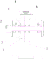
Fig. 1 is a schematic structural diagram of the present invention.
Fig. 2 is a left side view of fig. 1.
Fig. 3 is a schematic structural view of a ratchet type worm gear unidirectional force transmission speed reducing mechanism in specific use.
Detailed Description
The invention will be further described with reference to the following figures and examples:
as shown in the figure, provide the utility model discloses one-way biography power reduction gears of pawl formula worm gear, including case seat 1, be equipped with output shaft 2, worm 3 on the case seat 1, ratchet 4 fixes on output shaft 2 and rotates along with output shaft 2, and centering dish 5, worm wheel 6 pass through the bearing housing on output shaft 2 but do not rotate along with output shaft 2, and centering dish 5 is located 4 left sides of ratchet, and worm wheel 6 is located 4 right sides of ratchet, and 7 one end of connecting axle are fixed on centering dish 5, and the other end is fixed on worm wheel 6, and pawl 8 sets up on the connecting axle, and spring 9 one end is fixed on centering dish 5, and the other end is fixed at pawl 8 middle part, worm wheel 6 meshes with worm 3 mutually.
The number of the connecting shafts 7 is three, one connecting shaft 7 is matched with one pawl 8 and one spring 9, so that the number of the pawls is 3, and the number of the springs is 3.
When the lifting mechanism is used specifically, as shown in fig. 3, the lifting motor 10 is connected with the left end of the winding drum 11, the right end of the winding drum 11 is connected with the output shaft 2, and the descending motor 12 is connected with the worm 3. When the ascending motor 10 is normally started, the winding drum 11 is driven to rotate positively, the winding drum 11 drives the output shaft 2 to rotate, the output shaft 2 drives the ratchet wheel 4 to rotate, namely, the ratchet wheel 4 rotates clockwise in the drawing 2, at the moment, the descending motor 12, the worm 3, the worm wheel 6, the centering disc 5 and the pawl 8 are not moved, the ratchet wheel and the pawl move relatively and are not locked, and the heavy object ascends under the action of the steel wire rope of the winding drum 2. When the ascending motor 10 stops, the ascending motor is locked by a brake, the winding drum 11 and the output shaft 2 do not rotate any more, the ratchet wheel 4 does not rotate clockwise, and meanwhile, the ratchet wheel 4 is locked by the pawl 8 and cannot rotate anticlockwise, namely, the output shaft 2 and the winding drum 11 cannot rotate reversely, so that the heavy object is prevented from sliding downwards. When the descending motor 12 is started, the descending motor 12 drives the worm 3 to move, so that the worm wheel 6, the centering disc 5 and the pawl 8 are driven to rotate anticlockwise in the drawing 2, the ratchet wheel 4 is unlocked, the brake of the ascending motor 10 is released, the ascending motor 10, the winding drum 11 and the output shaft 2 are in a free state, the winding drum 11 is driven to rotate reversely under the action of the gravity of a heavy object hung on a steel wire rope, the winding drum 11 drives the output shaft 2 and the ratchet wheel 4 to rotate reversely, and the heavy object descends.
Claims (2)
1. The utility model provides a one-way biography power reduction gears of pawl formula worm gear, includes the case seat, its characterized in that: the box seat is provided with an output shaft and a worm, the ratchet wheel is fixed on the output shaft and rotates along with the output shaft, the centering disc and the worm wheel are sleeved on the output shaft through a bearing but do not rotate along with the output shaft, the centering disc is located on the left side of the ratchet wheel, the worm wheel is located on the right side of the ratchet wheel, one end of the connecting shaft is fixed on the centering disc, the other end of the connecting shaft is fixed on the worm wheel, the pawl is arranged on the connecting shaft, one end of the spring is fixed on the centering disc, the other end.
2. The ratchet type worm gear unidirectional force transmission speed reducing mechanism according to claim 1, characterized in that: the connecting shafts are three, one connecting shaft is matched with one pawl and one spring, so that the number of the pawls is 3, and the number of the springs is 3.
Priority Applications (1)
| Application Number | Priority Date | Filing Date | Title |
|---|---|---|---|
| CN202020345384.1U CN212198297U (en) | 2020-03-18 | 2020-03-18 | Pawl type worm gear one-way force transmission speed reducing mechanism |
Applications Claiming Priority (1)
| Application Number | Priority Date | Filing Date | Title |
|---|---|---|---|
| CN202020345384.1U CN212198297U (en) | 2020-03-18 | 2020-03-18 | Pawl type worm gear one-way force transmission speed reducing mechanism |
Publications (1)
| Publication Number | Publication Date |
|---|---|
| CN212198297U true CN212198297U (en) | 2020-12-22 |
Family
ID=73823344
Family Applications (1)
| Application Number | Title | Priority Date | Filing Date |
|---|---|---|---|
| CN202020345384.1U Active CN212198297U (en) | 2020-03-18 | 2020-03-18 | Pawl type worm gear one-way force transmission speed reducing mechanism |
Country Status (1)
| Country | Link |
|---|---|
| CN (1) | CN212198297U (en) |
-
2020
- 2020-03-18 CN CN202020345384.1U patent/CN212198297U/en active Active
Similar Documents
| Publication | Publication Date | Title |
|---|---|---|
| CN111392623A (en) | Pawl type worm gear one-way force transmission speed reducing mechanism | |
| CN111285277A (en) | Worm gear type ratchet wheel type winding mechanism | |
| JP2016537281A (en) | Energy saving traction type elevator and its energy saving method | |
| CN212198290U (en) | Worm gear type ratchet wheel type winding mechanism | |
| CN112299272A (en) | Portable embedded direct current electric block | |
| CN113187866A (en) | Electric cylinder with controllable power-loss fall-back speed | |
| CN101823658B (en) | Manual wire-drawing type rescue device without machine room for elevator | |
| CN111332975A (en) | Portable hoist convenient to quick travel control | |
| CN214946179U (en) | Electric cylinder with controllable power-loss fall-back speed | |
| CN212198297U (en) | Pawl type worm gear one-way force transmission speed reducing mechanism | |
| CN1746099A (en) | Clutch brake | |
| CN201932854U (en) | Planetary-transmission lifting mechanism used by crane | |
| CN101745188A (en) | High-rise escape apparatus | |
| CN213738346U (en) | Portable embedded direct current electric block | |
| CN115849230A (en) | Anti-falling safety braking device for cabin module lifting | |
| WO2011057464A1 (en) | Gravity-type and non energy consumption descent decelerating/controlling speed mechanical device | |
| CN211499976U (en) | Spring return type lifting mechanism | |
| CN105016162B (en) | A kind of lift rescue device | |
| CN201808982U (en) | Manual line-pulling type rescue device of elevator without machine room | |
| CN209751982U (en) | multi-person slow-descending escape device | |
| CN114148932A (en) | Hoisting device | |
| CN201351101Y (en) | Double-key pedal hanging basket hoisting machine | |
| CN113716428A (en) | Mechanical energy storage elevator system based on flywheel energy storage | |
| CN111994815A (en) | Safety building hoisting accessory | |
| CN2394889Y (en) | Brake release type circular chain hand hoist |
Legal Events
| Date | Code | Title | Description |
|---|---|---|---|
| GR01 | Patent grant | ||
| GR01 | Patent grant |