CN212193367U - Household dicer - Google Patents
Household dicer Download PDFInfo
- Publication number
- CN212193367U CN212193367U CN202020471692.9U CN202020471692U CN212193367U CN 212193367 U CN212193367 U CN 212193367U CN 202020471692 U CN202020471692 U CN 202020471692U CN 212193367 U CN212193367 U CN 212193367U
- Authority
- CN
- China
- Prior art keywords
- plate part
- cutter
- flat plate
- group
- transverse
- Prior art date
- Legal status (The legal status is an assumption and is not a legal conclusion. Google has not performed a legal analysis and makes no representation as to the accuracy of the status listed.)
- Expired - Fee Related
Links
- 238000005452 bending Methods 0.000 claims abstract description 5
- 235000013399 edible fruits Nutrition 0.000 description 7
- 241000219112 Cucumis Species 0.000 description 6
- 235000015510 Cucumis melo subsp melo Nutrition 0.000 description 6
- 244000141359 Malus pumila Species 0.000 description 2
- FJJCIZWZNKZHII-UHFFFAOYSA-N [4,6-bis(cyanoamino)-1,3,5-triazin-2-yl]cyanamide Chemical compound N#CNC1=NC(NC#N)=NC(NC#N)=N1 FJJCIZWZNKZHII-UHFFFAOYSA-N 0.000 description 2
- 235000021016 apples Nutrition 0.000 description 2
- 230000009286 beneficial effect Effects 0.000 description 2
- 244000099147 Ananas comosus Species 0.000 description 1
- 235000007119 Ananas comosus Nutrition 0.000 description 1
- 241000220324 Pyrus Species 0.000 description 1
- 244000088415 Raphanus sativus Species 0.000 description 1
- 235000006140 Raphanus sativus var sativus Nutrition 0.000 description 1
- 244000061458 Solanum melongena Species 0.000 description 1
- 235000002597 Solanum melongena Nutrition 0.000 description 1
- 244000061456 Solanum tuberosum Species 0.000 description 1
- 235000002595 Solanum tuberosum Nutrition 0.000 description 1
- 238000010411 cooking Methods 0.000 description 1
- 238000005034 decoration Methods 0.000 description 1
- 230000007547 defect Effects 0.000 description 1
- 235000013372 meat Nutrition 0.000 description 1
- 238000000034 method Methods 0.000 description 1
- 238000012986 modification Methods 0.000 description 1
- 230000004048 modification Effects 0.000 description 1
- 239000002245 particle Substances 0.000 description 1
- 235000021017 pears Nutrition 0.000 description 1
- 235000012015 potatoes Nutrition 0.000 description 1
Images


Landscapes
- Food-Manufacturing Devices (AREA)
Abstract
The invention relates to a household dicer, which comprises a supporting shell, a cutter bearing piece, a longitudinal cutter group, a transverse prop group and a cutting cutter, wherein the cutter bearing piece is fixed in an inner cavity of the supporting shell; the cutter supporting piece is integrally formed and comprises a first plate part, a second plate part and a third plate part, the second plate part and the third plate part are positioned on the same side of the first plate part, the second plate part and the third plate part are mutually parallel and have the bending angle of not less than 0 degrees and not more than 60 degrees relative to the first plate part, and a gap S is formed between the second plate part and the third plate part; the longitudinal cutter group is fixed on the first flat plate part, the transverse prop group is fixed on the second flat plate part, the cutting cutter is fixed on the third flat plate part, and the cutting edge of the cutting cutter is flush with the top of a cutter B of the transverse prop group; this technical scheme need not with the help of extra cutter, and the dicing is even, easy operation, and is efficient, convenient and practical.
Description
Technical Field
The invention relates to a dicer, in particular to a household dicer.
Background
The development of each field of China society is rapid, the division of work is more and more delicate, and the work efficiency is more and more high, but in the aspect of family life, a great part of people are not good at doing housework, and even if the melons and fruits are required to be cut into small pieces with uniform sizes, the cutting is simply and difficultly performed.
At present, each large sales network is provided with a special household dicer, but generally, melons and fruits are cut into thick slices by a cutter manually, then the thick slices are put into the dicer for press cutting, and then the dicing is carried out.
Disclosure of Invention
The invention aims to solve the technical problem of making up the defects of the prior art and provide a household dicer which does not need an additional cutter, is simple to operate, is convenient and practical.
To solve the technical problems, the technical scheme of the invention is as follows:
a household dicer is characterized in that: the cutting tool comprises a supporting shell, a tool bearing piece, a longitudinal tool set, a transverse tool set and a cutting tool, wherein the tool bearing piece is fixed in an inner cavity of the supporting shell;
the cutter supporting piece is integrally formed and comprises a first plate part, a second plate part and a third plate part, the second plate part and the third plate part are positioned on the same side of the first plate part, the second plate part and the third plate part are mutually parallel and have the bending angle of not less than 0 degrees and not more than 60 degrees relative to the first plate part, and a gap S is formed between the second plate part and the third plate part;
the longitudinal cutter group is fixed on the first flat plate part and comprises a plurality of mutually independent cutters A which are longitudinally arranged in parallel, the transverse intervals of the adjacent cutters A are equal, and the cutting edges of the cutters A point to the rear;
the transverse prop group is fixed on the second flat plate part and is positioned at the left front part or the right front part of the longitudinal cutter group, the transverse prop group comprises a plurality of mutually independent cutters B, the cutters B are transversely arranged in parallel, and the longitudinal intervals of the adjacent cutters B are equal; correspondingly, if the transverse prop group is positioned at the left front part of the longitudinal cutter group, the cutting edge of the cutter B points to the right; if the transverse prop group is positioned at the right front of the longitudinal cutter group, the cutting edge of the cutter B points to the left;
the extension surface of the cutter A of the longitudinal cutter group does not intersect with the cutter B of the transverse prop group, and the extension surface of the cutter B of the transverse prop group does not intersect with the cutter A of the longitudinal cutter group;
the cutting tool is fixed on the third flat plate part, and the cutting edge of the cutting tool is flush with the top of the cutter B of the transverse prop group.
Further, still include the tray, the tray matches the use with the support casing components of a whole that can function independently.
Further, the bottom surface of the supporting shell forms an angle beta with the top surface, when the bottom surface of the supporting shell is horizontally placed, the first flat plate part of the cutter supporting piece is positioned at the high end of the supporting shell, and the third flat plate part is positioned at the low end of the supporting shell.
Further, the support shell is a triangular prism-shaped shell and comprises a first top end, a second top end and a third top end, and when the bottom surface of the support shell is placed horizontally, the first top end is lower than the second top end and the third top end.
Further, the contact surfaces of the cutter bearing piece and the supporting shell are respectively a first right-angle side surface, a second right-angle side surface and an inclined side surface, the longitudinal cutter group is close to the first right-angle side surface, and the transverse prop group is close to the second right-angle side surface.
Furthermore, the cutter bearing piece is welded with a guide piece, the guide piece is in a right-angle triangular column shape and comprises a longitudinal guide plate, a transverse guide plate and a return guide plate, the longitudinal guide plate is parallel to the first right-angle side face of the supporting shell, and the transverse guide plate is parallel to the second right-angle side face of the supporting shell.
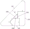
Further, the spacing between the longitudinal guide plate of the guide and the first right-angled side of the support housing is X, X =100 mm; the distance between the transverse guide plate of the guide and the second right-angled side surface of the support housing is Y, Y =100 mm; the distance between the return guide plate of the guide and the inclined side of the support housing is W, W =80 mm.
Furthermore, a plurality of cutters A of the longitudinal cutter group and a plurality of cutters B of the transverse prop group are arranged in a V shape of 90 degrees, and the cutting edges face the V-shaped bell mouth.
The invention can achieve the following beneficial effects:
1) firstly, longitudinally cutting melons and fruits to be processed through a longitudinal cutter set, transversely cutting the melons and fruits through a transverse cutter set, and finally forming dices through a cutting cutter without using an additional cutter;
2) the diced meat has consistent size and uniform particles, is beautiful and is beneficial to the consistency of cooking;
3) in the processing process, the melon and fruit is pushed forwards and laterally pushed only by manpower, the operation is simple, the efficiency is high, and the operation is convenient and practical.
Drawings
FIG. 1 is a perspective view of an embodiment of the present invention;
FIG. 2 is a top view of an embodiment of the present invention;
FIG. 3 is a view from the direction A of FIG. 2;
FIG. 4 is a side view of a support housing of an embodiment of the present invention placed on an anvil plate;
FIG. 5 is a cross-sectional view of a support housing of an embodiment of the present invention placed on an anvil;
FIG. 6 is a view of the tray covered on the support housing in an embodiment of the present invention;
FIG. 7 is a view of an embodiment of the present invention with the tray positioned below the support housing;
FIG. 8 is a perspective view of a support housing in an embodiment of the present invention;
FIG. 9 is a top view of a support housing in an embodiment of the present invention;
FIG. 10 is a view in the direction C of FIG. 9;
FIG. 11 is a perspective view of a tray in an embodiment of the present invention;
FIG. 12 is a front view of a tool holder in an embodiment of the invention;
FIG. 13 is a top view of a tool holder in an embodiment of the present invention;
FIG. 14 is a perspective view of a tool holder in an embodiment of the invention;
FIG. 15 is a top view of a cutting tool in an embodiment of the present invention;
in the figure: 1-support housing, 101-first top end, 102-second top end, 103-third top end, 2-tray, 3-knife holder, 301-first plate section, 302-second plate section, 303-third plate section, 304-guide, 3041-longitudinal guide, 3042-transverse guide, 3043-return guide, 305-second right-angled side, 306-first right-angled side, 307-oblique side, 4-longitudinal knife set, 5-transverse prop set, 6-cutting knife, 7-chopping block.
Detailed Description
The present invention will be described in further detail with reference to the accompanying drawings and specific embodiments.
Examples
A household dicer comprises a supporting shell 1, a cutter bearing piece 3, a longitudinal cutter group 4, a transverse prop group 5 and a cutting cutter 6, wherein the cutter bearing piece 3 is welded and fixed in an inner cavity of the supporting shell 1;
the cutter supporting piece 3 is integrally formed by cutting and bending a flat plate and comprises a first flat plate part 301, a second flat plate part 302 and a third flat plate part 303, the second flat plate part 302 and the third flat plate part 303 are positioned on the same side of the first flat plate part 301, the second flat plate part 302 and the third flat plate part 303 are parallel to each other, the bending angle of the second flat plate part 302 and the third flat plate part 303 relative to the first flat plate part 301 is not less than 0 degree and not more than 60 degrees, a gap S is formed between the second flat plate part 302 and the third flat plate part 303, the selected gap S is =11 degrees, and the gap S =;
the longitudinal cutter group 4 is fixed on the first flat plate part 301 and comprises 10 mutually independent cutters A, the 10 cutters A are longitudinally arranged in parallel, the transverse distance between every two adjacent cutters A is 8mm, and the cutting edges of the cutters A point to the rear;
the transverse prop group 5 is fixed on the second plate part 302 and is positioned at the left front part or the right front part of the longitudinal cutter group 4, the transverse prop group 5 comprises 10 mutually independent cutters B, the 10 cutters B are transversely arranged in parallel, and the longitudinal distance between every two adjacent cutters B is 8 mm; correspondingly, if the transverse prop group 5 is positioned at the left front part of the longitudinal cutter group 4, the cutting edge of the cutter B points to the right; if the transverse prop group 5 is positioned at the right front of the longitudinal cutter group 4, the cutting edge of the cutter B points to the left; according to the technical consideration that most people are used to use the right hand, the transverse prop group 5 is arranged at the right front of the longitudinal cutter group 4;
the extension surface of the cutter A of the longitudinal cutter group 4 does not intersect with the cutter B of the transverse prop group 5, and the extension surface of the cutter B of the transverse prop group 5 does not intersect with the cutter A of the longitudinal cutter group 4, so that the effective processing range is ensured;
the cutting tool 6 is fixed on the third flat plate part 303, the cutting edge of the cutting tool 6 is flush with the top of the cutter B of the transverse tool set 5, the cutting tool 6 is fixed below the tool support 3, and the distance between the cutting edge of the cutting tool 6 and the third flat plate part 303 of the tool support 3 is 8 mm.
The tray 2 is matched with the support shell 1 in a split mode, the tray 2 can be covered on the support shell 1, and the tray 2 can also be placed below the support shell 1; when the support device is used, the support shell 1 can be directly placed on the chopping board 7, the processed dices are received by the chopping board 7, and certainly, the support shell 1 can also be directly placed on the tray 2, and the processed dices are received by the tray 2, so that a user can conveniently select the support shell; when the device is not applicable, the tray 2 can be covered on the supporting shell 1, so that each cutter is sealed and kept clean.
The bottom surface of the supporting shell 1 forms an angle beta with the top surface, when the bottom surface of the supporting shell 1 is horizontally placed, the first flat plate part 301 of the cutter supporting piece 3 is positioned at the high end of the supporting shell 1, and the third flat plate part 303 is positioned at the low end of the supporting shell 1, so that the use comfort is improved.
In order to reduce the volume of the device while ensuring an effective working range, the support housing 1 is designed as a triangular prism housing comprising a first top end 101, a second top end 102 and a third top end 103, the first top end 101 being lower than the second top end 102 and the third top end 103 when the bottom surface of the support housing 1 is horizontally placed.
The contact surfaces of the cutter support 3 and the support shell 1 are a first right-angle side 306, a second right-angle side 305 and an inclined side 307 respectively, the longitudinal cutter set 4 is close to the first right-angle side 306, and the transverse prop set 5 is close to the second right-angle side 305.
The cutter support 3 is welded with a guide 304, the guide 304 is in a right triangular prism shape and includes a longitudinal guide plate 3041, a transverse guide plate 3042 and a return guide plate 3043, the longitudinal guide plate 3041 is parallel to the first right-angled side surface 306 of the support housing 1, and the transverse guide plate 3042 is parallel to the second right-angled side surface 305 of the support housing 1.
For convenience of household use, the present embodiment is particularly optimized for dimensions, the distance between the longitudinal guide plate 3041 of the guide 304 and the first right-angled side 306 of the support housing 1 being X, X =100 mm; the spacing between the lateral guide plate 3042 of the guide 304 and the second right-angled side surface 305 of the support housing 1 is Y, Y =100 mm; the spacing between the return guide plate 3043 of the guide 304 and the oblique side surface 307 of the support housing 1 is W, W =80 mm.
In order to save labor in processing and operation, 10 cutters A of the longitudinal cutter group 4 and 10 cutters B of the transverse prop group 5 are designed to be arranged in a V shape of 90 degrees, and the cutting edges face the V-shaped bell mouth.
The device is suitable for potatoes, eggplants, apples, radishes, apples, pears, pineapples and the like.
Use of this example:
1) the tray 2 covered on the support housing 1 is taken down;
2) the device is placed on a chopping board 7 or a tray 2;
3) the melon and fruit to be processed is longitudinally cut by a longitudinal cutter set 4, transversely cut by a transverse cutter set 5, and finally cut into 8mm square dices by a cutting cutter 6.
Of course, under the teaching of the present invention, the skilled in the art can reasonably change the cutter spacing and S value of the longitudinal cutter set 4 and the transverse cutter set 5, so as to obtain other sizes of diced fruits, such as 10mm square, 12mm square, etc.
In the description of the present invention, words such as "inner", "outer", "upper", "lower", "front", "rear", etc., indicating orientations or positional relationships, are used for convenience in describing the present invention, and do not indicate or imply that the indicated devices or elements must have a particular orientation, be constructed and operated in a particular orientation, and thus, should not be construed as limiting the present invention.
The above description is only one embodiment of the present invention, and the scope of the present invention is not limited to the above embodiments, and it should be noted that, for those skilled in the art, several modifications and decorations can be made without departing from the spirit of the present invention.
Claims (8)
1. A household dicer is characterized in that: the cutting tool comprises a supporting shell (1), a tool bearing piece (3), a longitudinal tool set (4), a transverse tool set (5) and a cutting tool (6), wherein the tool bearing piece (3) is fixed in an inner cavity of the supporting shell (1);
the cutter supporting piece (3) is integrally formed and comprises a first flat plate part (301), a second flat plate part (302) and a third flat plate part (303), the second flat plate part (302) and the third flat plate part (303) are positioned on the same side of the first flat plate part (301), the second flat plate part (302) and the third flat plate part (303) are parallel to each other, the bending angle of the second flat plate part (302) and the third flat plate part (303) relative to the first flat plate part (301) is not less than 0 degree and not more than 60 degrees, and a gap S is formed between the second flat plate part (302) and the third flat plate part (303;
the longitudinal cutter group (4) is fixed on the first flat plate part (301) and comprises a plurality of mutually independent cutters A which are longitudinally arranged in parallel, the transverse intervals of the adjacent cutters A are equal, and the cutting edges of the cutters A point to the rear;
the transverse prop group (5) is fixed on the second flat plate part (302) and is positioned at the left front part or the right front part of the longitudinal cutter group (4), the transverse prop group (5) comprises a plurality of mutually independent cutters B, the plurality of cutters B are transversely arranged in parallel, and the longitudinal intervals of the adjacent cutters B are equal; correspondingly, if the transverse prop group (5) is positioned at the left front part of the longitudinal cutter group (4), the cutting edge of the cutter B points to the right; if the transverse prop group (5) is positioned at the right front of the longitudinal cutter group (4), the cutting edge of the cutter B points to the left;
the extension surface of the cutter A of the longitudinal cutter group (4) does not intersect with the cutter B of the transverse prop group (5), and the extension surface of the cutter B of the transverse prop group (5) does not intersect with the cutter A of the longitudinal cutter group (4);
the cutting tool (6) is fixed on the third flat plate part (303), and the cutting edge of the cutting tool (6) is flush with the top of the cutter B of the transverse prop group (5).
2. A domestic dicer as claimed in claim 1, wherein: the tray is characterized by further comprising a tray (2), wherein the tray (2) and the supporting shell (1) are used in a split matching mode.
3. A domestic dicer as claimed in claim 1, wherein: the bottom surface and the top surface of the supporting shell (1) form an angle beta, when the bottom surface of the supporting shell (1) is horizontally placed, the first flat plate part (301) of the cutter supporting piece (3) is located at the high end of the supporting shell (1), and the third flat plate part (303) is located at the low end of the supporting shell (1).
4. A domestic dicer as claimed in claim 3, wherein: the supporting shell (1) is a triangular prism-shaped shell and comprises a first top end (101), a second top end (102) and a third top end (103), and when the bottom surface of the supporting shell (1) is placed horizontally, the first top end (101) is lower than the second top end (102) and the third top end (103).
5. A domestic dicer as claimed in claim 4, wherein: the contact surfaces of the cutter supporting piece (3) and the supporting shell (1) are a first right-angle side surface (306), a second right-angle side surface (305) and an inclined side surface (307), the longitudinal cutter group (4) is close to the first right-angle side surface (306), and the transverse prop group (5) is close to the second right-angle side surface (305).
6. A domestic dicer as claimed in claim 5, wherein: the cutter supporting piece (3) is welded with a guide piece (304), the guide piece (304) is in a right-angle triangular column shape and comprises a longitudinal guide plate (3041), a transverse guide plate (3042) and a return guide plate (3043), the longitudinal guide plate (3041) is parallel to a first right-angle side surface (306) of the supporting shell (1), and the transverse guide plate (3042) is parallel to a second right-angle side surface (305) of the supporting shell (1).
7. A domestic dicer as claimed in claim 6, wherein: -the distance between a longitudinal guide plate (3041) of the guide (304) and a first right-angled side (306) of the support housing (1) is X, X =100 mm; the spacing between the transverse guide plate (3042) of the guide (304) and the second right-angled side (305) of the support housing (1) is Y, Y =100 mm; the distance between the return guide plate (3043) of the guide (304) and the oblique side surface (307) of the support housing (1) is W, W =80 mm.
8. A domestic dicer as claimed in claim 1, wherein: the cutters A of the longitudinal cutter group (4) and the cutters B of the transverse prop group (5) are arranged in a 90-degree V shape, and the cutting edges face the V-shaped bell mouth.
Priority Applications (1)
| Application Number | Priority Date | Filing Date | Title |
|---|---|---|---|
| CN202020471692.9U CN212193367U (en) | 2020-04-03 | 2020-04-03 | Household dicer |
Applications Claiming Priority (1)
| Application Number | Priority Date | Filing Date | Title |
|---|---|---|---|
| CN202020471692.9U CN212193367U (en) | 2020-04-03 | 2020-04-03 | Household dicer |
Publications (1)
| Publication Number | Publication Date |
|---|---|
| CN212193367U true CN212193367U (en) | 2020-12-22 |
Family
ID=73829807
Family Applications (1)
| Application Number | Title | Priority Date | Filing Date |
|---|---|---|---|
| CN202020471692.9U Expired - Fee Related CN212193367U (en) | 2020-04-03 | 2020-04-03 | Household dicer |
Country Status (1)
| Country | Link |
|---|---|
| CN (1) | CN212193367U (en) |
-
2020
- 2020-04-03 CN CN202020471692.9U patent/CN212193367U/en not_active Expired - Fee Related
Similar Documents
| Publication | Publication Date | Title |
|---|---|---|
| CN210589544U (en) | Vegetable dicing machine | |
| CN212193367U (en) | Household dicer | |
| CN211322826U (en) | Raw beef cutting machine | |
| CN105559642A (en) | Multifunctional shredder | |
| CN204868958U (en) | Hand slicer | |
| CN106826965A (en) | A kind of rectangle push type food slicer | |
| CN211389057U (en) | Cutting device is used in marine product processing | |
| CN102326614B (en) | Squid or kidney pattern cutter | |
| CN201501000U (en) | Bread slicer | |
| CN210407056U (en) | Tomato removes base of a fruit device | |
| EP3584045B1 (en) | Mould support, cutter module and cutter machine for pieces of fruit, in particular pineapple | |
| CN105835092A (en) | Double-handle straight-grain hollow slicing knife | |
| CN212947952U (en) | Potato quick slicing device | |
| CN207710892U (en) | Simple slice of vegetable yarn cutter | |
| CN214394322U (en) | Fresh bamboo shoots section device is used in production of bamboo shoots can | |
| CN212421368U (en) | Slicing scissors | |
| CN212394700U (en) | Auxiliary vegetable cutting kitchen tool for single-arm disabled people | |
| CN220882586U (en) | Operating table for vegetable processing | |
| CN211867867U (en) | Bean curd dicing tool | |
| CN216914037U (en) | Slicing device for agricultural product processing | |
| CN218921455U (en) | Machine for cutting fish flower | |
| CN211565973U (en) | Quick strip-cutting kitchen knife | |
| CN213499420U (en) | Multi-purpose hot pepper gang tool that cuts | |
| CN212352155U (en) | Chinese yam slicing device | |
| CN107775710A (en) | A kind of simple slice of vegetable yarn cutter |
Legal Events
| Date | Code | Title | Description |
|---|---|---|---|
| GR01 | Patent grant | ||
| GR01 | Patent grant | ||
| CF01 | Termination of patent right due to non-payment of annual fee |
Granted publication date: 20201222 |
|
| CF01 | Termination of patent right due to non-payment of annual fee |