CN212182499U - Heat dissipation device of lithium ion power battery - Google Patents
Heat dissipation device of lithium ion power battery Download PDFInfo
- Publication number
- CN212182499U CN212182499U CN202020872489.2U CN202020872489U CN212182499U CN 212182499 U CN212182499 U CN 212182499U CN 202020872489 U CN202020872489 U CN 202020872489U CN 212182499 U CN212182499 U CN 212182499U
- Authority
- CN
- China
- Prior art keywords
- heat dissipation
- cooling
- box
- installation box
- cooling plate
- Prior art date
- Legal status (The legal status is an assumption and is not a legal conclusion. Google has not performed a legal analysis and makes no representation as to the accuracy of the status listed.)
- Expired - Fee Related
Links
Images


Classifications
-
- Y—GENERAL TAGGING OF NEW TECHNOLOGICAL DEVELOPMENTS; GENERAL TAGGING OF CROSS-SECTIONAL TECHNOLOGIES SPANNING OVER SEVERAL SECTIONS OF THE IPC; TECHNICAL SUBJECTS COVERED BY FORMER USPC CROSS-REFERENCE ART COLLECTIONS [XRACs] AND DIGESTS
- Y02—TECHNOLOGIES OR APPLICATIONS FOR MITIGATION OR ADAPTATION AGAINST CLIMATE CHANGE
- Y02E—REDUCTION OF GREENHOUSE GAS [GHG] EMISSIONS, RELATED TO ENERGY GENERATION, TRANSMISSION OR DISTRIBUTION
- Y02E60/00—Enabling technologies; Technologies with a potential or indirect contribution to GHG emissions mitigation
- Y02E60/10—Energy storage using batteries
Abstract
The utility model discloses a heat dissipation device of a lithium ion power battery, which comprises a top cover, an installation box, an installation seat, a clamping piece, a reciprocating mechanism, a temperature sensor and a heat dissipation mechanism; the top cover is connected to the top of the installation box through a hinge; the bottom in the installation box is horizontally provided with an installation seat; the clamping pieces are arranged at two ends of the upper part of the mounting seat; the reciprocating mechanism is arranged at the upper part of the mounting seat and drives the clamping piece to move; the temperature sensor is arranged on the inner wall of the installation box; the heat dissipation mechanism is arranged inside and outside the installation box. The utility model increases the distance between the lithium ion power batteries, thereby facilitating heat dissipation; the air cooling and the water cooling are combined, so that the heat dissipation effect is good, and the heat dissipation efficiency is improved; the fan and the water pump are prevented from being always in a working state, and the service lives of the fan and the water pump are prolonged; the cooling liquid can be recycled, and resources are saved.
Description
Technical Field
The utility model relates to a heat abstractor especially relates to a lithium ion power battery's heat abstractor.
Background
The lithium ion power battery is a novel high-energy battery successfully developed in the 20 th century, the negative electrode of the battery is made of materials such as graphite, the positive electrode of the battery is made of lithium iron phosphate, lithium cobaltate, lithium titanate and the like, and the lithium ion power battery has the advantages of high energy, high battery voltage, wide working temperature range, long storage life and the like. The lithium ion power battery can generate a large amount of heat in the charging or discharging process, and the battery is short-circuited or exploded due to overhigh heat, so that safety accidents occur.
The existing heat dissipation device of the lithium ion power battery only dissipates heat through air cooling, and the heat dissipation effect is poor; and most of the existing lithium ion power batteries are battery packs, a plurality of batteries are connected in series and installed together, and the heat dissipation of the contact part of the batteries is difficult, so that the batteries are easy to short circuit or explode.
SUMMERY OF THE UTILITY MODEL
Utility model purpose: in order to solve the problems existing in the prior art, the utility model provides a lithium ion power battery's heat abstractor is realized having cooling body, reducing charge-discharge in-process battery temperature.
The technical scheme is as follows: the heat dissipation device of the utility model comprises a top cover, an installation box, an installation seat, a clamping piece, a reciprocating mechanism, a temperature sensor and a heat dissipation mechanism; the top cover is connected to the top of the installation box through a hinge; the bottom in the installation box is horizontally provided with an installation seat; the clamping pieces are arranged at two ends of the upper part of the mounting seat; the reciprocating mechanism is arranged at the upper part of the mounting seat and drives the clamping piece to move; the temperature sensor is arranged on the inner wall of the installation box; the heat dissipation mechanism is arranged inside and outside the installation box.
The reciprocating mechanism comprises a rotary table, a moving block, a second connecting rod, a first connecting rod, a rotating rod, a second bevel gear, a first bevel gear, a rotating shaft and a mounting plate; the second bevel gear is arranged in the mounting seat and connected with the driven shaft, a rotating rod is arranged at the top of the driven shaft, two ends of the rotating rod can rotate and is connected with a first connecting rod, and the other end of the first connecting rod can rotate and is connected with a second connecting rod; the other end of the second connecting rod can rotate and is connected with a moving block, the top end of the moving block is provided with an installation plate, and the side surface of the installation plate is provided with a plurality of clamping pieces; the side face of the second bevel gear is meshed with the first bevel gear, the other side of the first bevel gear is connected with the rotating shaft, the other end of the rotating shaft extends out of the installation box and is provided with a rotatable turntable, and a handle is arranged on the turntable.
The heat dissipation mechanism comprises a first heat dissipation mechanism, a second heat dissipation mechanism and a cooling box, the first heat dissipation mechanism is arranged inside the installation box, the cooling box is arranged on one side of the outer portion of the installation box, a circulation mechanism for driving cooling liquid to circulate is arranged between the first heat dissipation mechanism and the cooling box, and a cooling mechanism is arranged in the cooling box; the second heat dissipation mechanism is arranged on the installation box.
The first heat dissipation mechanism comprises a top cooling plate, an intermediate cooling plate, a bottom cooling plate and a condensing coil; the top cooling plate is arranged at the bottom of the top cover, the middle cooling plate is arranged in the middle of the inside of the mounting box, the middle cooling plate is provided with a plurality of clamping pieces which are arranged alternately, the bottom cooling plate is arranged at the top of the mounting seat, and the top cooling plate, the middle cooling plate and the bottom cooling plate are all internally provided with condensing coils.
The circulating mechanism comprises water supply branch pipes, a water supply main pipe, backflow branch pipes, a backflow main pipe and a water pump, one ends of condensing coils inside the top cooling plate, the middle cooling plate and the bottom cooling plate are communicated with the backflow branch pipes, the other ends of the backflow branch pipes are communicated with the backflow main pipe, the backflow main pipe is communicated with the water pump, the other ends of the condensing coils are communicated with the water supply branch pipes, the other ends of the water supply branch pipes are communicated with the water supply main pipe, and a water inlet is formed in the middle of the water supply main pipe.
The cooling body includes the heat conduction post, the heat conduction post runs through the cooling box and keeps away from one side outer wall of install bin, the heat conduction post is equipped with a plurality ofly, is located the cooling box inside the heat conduction post part is cylindrical, is located the cooling box outside the heat conduction post part is the hemisphere.
The second heat dissipation mechanism comprises a heat dissipation opening, a fan and an air inlet, the air inlet is located on one side face of the installation box, the fan is installed on the air inlet, the heat dissipation opening is arranged on the side face, opposite to the air inlet, of the installation box, and the heat dissipation openings are multiple.
Further, cooling body still can comprise outlet pipe and condenser, the side intercommunication of outlet pipe one end and water pump, the outlet pipe other end stretches out the cooling tank outside and communicates with the condenser, the condenser top communicates with the drain pipe, and the drain pipe other end communicates with the cooling tank.
Has the advantages that: compared with the prior art, the beneficial effects of the utility model are as follows: 1. the reciprocating mechanism is adopted to fix the plurality of lithium ion power batteries separately, the arrangement distance is increased, heat dissipation is convenient, the batteries are cooled by air through the fan, the periphery of the batteries are cooled by cooling liquid in the condensation coil, the heat dissipation effect is good, the heat dissipation efficiency is increased, and short circuit or explosion of the lithium ion power batteries due to overhigh temperature is avoided; 2. the temperature in the installation box is monitored in real time through the temperature sensor, when the temperature is higher than a limit value, the fan is started for air cooling, and the water pump is started to pump cooling liquid in the condensation coil to the cooling box, so that the fan and the water pump are prevented from being always in a working state, the service lives of the fan and the water pump are prolonged, and resources are saved; 3. adopt cooling body to cool off the exhaust coolant liquid in the condensation coil, the coolant liquid rethread water supply branch pipe after the cooling gets back to in the condensation coil again carries out water-cooling to lithium ion power battery, and the coolant liquid can recycle resources are saved.
Drawings
Fig. 1 is a side sectional view of an installation box according to embodiment 1 of the present invention;
fig. 2 is a schematic view of the overall structure of embodiment 1 of the present invention;
fig. 3 is a top sectional view of the installation box according to embodiment 1 of the present invention;
fig. 4 is an overall side sectional view of embodiment 1 of the present invention;
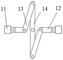
fig. 5 is a top sectional view of a mount according to embodiment 1 of the present invention;
fig. 6 is an overall side sectional view of embodiment 2 of the present invention.
Detailed Description
The technical solution of the present invention will be described in detail with reference to the drawings and the detailed description.
Example one
As shown in fig. 1, a mounting base 10 is horizontally arranged at the bottom in a mounting box 4, clamping pieces 20 are arranged at two ends of the top of the mounting base 10, a reciprocating mechanism for driving the clamping pieces 20 to move is arranged at the bottom of the clamping pieces 20, the top of the mounting box 4 is connected with a top cover 1 through a hinge, and a first heat dissipation mechanism is arranged in the mounting box 4; as shown in fig. 2, a cooling box 5 is arranged on one side of the outer part of the installation box 4; a circulating mechanism for driving cooling liquid to circulate is arranged between the first heat dissipation mechanism and the cooling box 5, the cooling box 5 is internally provided with a cooling mechanism, the installation box 4 is provided with a second heat dissipation mechanism, and the inner wall of the installation box 4 is provided with a temperature sensor 22, as shown in fig. 3.
The reciprocating mechanism comprises a moving block 11, a rotating rod 14, a second bevel gear 15, a first bevel gear 16, a rotating shaft 17 and a clamping piece 20, the second bevel gear 15 is installed in the middle of the inside of the installation seat 10, a driven shaft penetrates through the center of the second bevel gear 15, the rotating rod 14 is welded at the top of the driven shaft, two ends of the rotating rod 14 are rotatably connected with first connecting rods 13, the other ends of the first connecting rods 13 are rotatably connected with second connecting rods 12, and the other ends of the second connecting rods 12 are rotatably connected with the moving block 11, as shown in fig. 5; mounting plate 21 has all been welded on the top of movable block 11, and a plurality of holders 20 have all been welded to the side of mounting plate 21, and the side meshing of second bevel gear 15 has first bevel gear 16, and the welding of first bevel gear 16 opposite side has pivot 17, and the pivot 17 other end stretches out the installation box 4 outside and welds carousel 7, and carousel 7 edge rotation is connected with the handle.
As shown in fig. 4, the first heat dissipation mechanism includes a top cooling plate 2, an intermediate cooling plate 3, a bottom cooling plate 18 and a condensation coil 19, the top cooling plate 2 is installed at the bottom of the top cover 1, the bottom cooling plate 18 is installed at the top of the installation base 10, the intermediate cooling plate 3 is installed at the middle part inside the installation box 4, the intermediate cooling plate 3 is provided with a plurality of clamping members 20 and is arranged alternately with the clamping members 20, the condensation coil 19 is installed inside the top cooling plate 2, the intermediate cooling plate 3 and the bottom cooling plate 18, the circulation mechanism includes a water supply branch pipe 23, a water supply header pipe 24, a reflux branch pipe 26, a reflux header pipe 27 and a water pump 28, one end of the condensation coil 19 inside the top cooling plate 2, the intermediate cooling plate 3 and the bottom cooling plate 18 is communicated with the reflux branch pipe 26, the other end of the reflux branch pipe 26 is communicated with the same reflux header pipe 27, the reflux header pipe 27 is, the other end of the water supply branch pipe 23 is communicated with the same water supply main pipe 24, and the middle part of the water supply main pipe 24 is provided with a water inlet; the cooling mechanism comprises a plurality of heat conducting columns 25, the heat conducting columns 25 penetrate through the outer wall of one side, far away from the installation box 4, of the cooling box 5, the heat conducting columns 25 are cylindrical, the part, located inside the cooling box 5, of each heat conducting column 25 is hemispherical, and the part, located outside the cooling box 5, of each heat conducting column 25 is hemispherical; as shown in fig. 2, the second heat dissipation mechanism includes a plurality of heat dissipation openings 6, a fan 8, and an air inlet 9, the air inlet 9 is located on one side of the installation box 4, the fan 8 is installed on the air inlet 9, the heat dissipation openings 6 are located on the installation box 4 and on the opposite side to the air inlet 9, and the heat dissipation openings 6 are provided.
The working principle is as follows: the top cover 1 is opened, the lithium ion power battery is placed in the middle of the clamping part 20, the handle is utilized to rotate the rotating disc 7 to drive the rotating shaft 17 to rotate, the rotating shaft 17 drives the first bevel gear 16 to rotate, the first bevel gear 16 drives the driven shaft to rotate through the second bevel gear 15, the driven shaft drives the rotating rod 14 to rotate, the rotating rod 14 drives the two moving blocks 11 to move in opposite directions through the first connecting rod 13 and the second connecting rod 12, namely, the clamping part 20 is driven to move in opposite directions to separate and fix a plurality of lithium ion power batteries, the distance between the lithium ion power batteries is increased, heat dissipation is facilitated, the periphery of the battery is cooled by cooling liquid in the condensing coil 19, the temperature in the mounting box 4 is monitored in real time through the temperature sensor 22, when the temperature is higher than a limited value, the fan 8 is started to cool the battery, meanwhile, the water pump 28 is started to pump the cooling liquid in the condensing coil 19 to, the service lives of the fan 8 and the water pump 28 are prolonged, and resources are saved; the cooling liquid discharged from the interior of the condensing coil 19 is cooled through the heat-conducting column 25, the cooled cooling liquid returns to the interior of the condensing coil 19 again through the water supply branch pipe 23 to carry out water-cooling on the lithium ion power battery, and the cooling liquid can be recycled, so that resources are saved.
Example two
As shown in fig. 6, the present embodiment differs from embodiment 1 only in that the cooling mechanism includes a water outlet pipe 29 and a condenser 30, one end of the water outlet pipe 29 is communicated with the side surface of the water pump 28, the other end of the water outlet pipe 29 extends out of the interior of the cooling tank 5 and is communicated with the condenser 30, the top of the condenser 30 is communicated with a drain pipe, and the other end of the drain pipe is communicated with the cooling tank 5.
The working principle is as follows: the water pump 28 extracts the cooling liquid in the condensing coil 19 and leads into the condenser 30 through the water outlet pipe 29 for cooling, the cooled cooling liquid enters the cooling box 5 through the water outlet pipe, and then returns to the condensing coil 19 again through the water supply branch pipe 23 to carry out water cooling on the lithium ion power battery, so that the cooling liquid can be recycled, and resources are saved.
Claims (8)
1. The utility model provides a heat abstractor of lithium ion power battery which characterized in that: the device comprises a top cover (1), an installation box (4), an installation seat (10), a clamping piece (20), a reciprocating mechanism, a temperature sensor (22) and a heat dissipation mechanism; the top cover (1) is connected to the top of the installation box (4) through a hinge; a mounting seat (10) is horizontally arranged at the bottom in the mounting box (4); the clamping pieces (20) are arranged at two ends of the upper part of the mounting seat (10); the reciprocating mechanism is arranged at the upper part of the mounting seat (10) and drives the clamping piece (20) to move; the temperature sensor (22) is arranged on the inner wall of the installation box (4); the heat dissipation mechanism is arranged inside and outside the installation box (4).
2. The heat dissipation device of the lithium-ion power battery as defined in claim 1, wherein the reciprocating mechanism comprises a rotary table (7), a moving block (11), a second connecting rod (12), a first connecting rod (13), a rotating rod (14), a second bevel gear (15), a first bevel gear (16), a rotating shaft (17) and a mounting plate (21); the second bevel gear (15) is installed inside the installation seat (10), the second bevel gear (15) is connected with a driven shaft, a rotating rod (14) is arranged at the top of the driven shaft, two ends of the rotating rod (14) can rotate and are connected with a first connecting rod (13), and the other end of the first connecting rod (13) can rotate and is connected with a second connecting rod (12); the other end of the second connecting rod (12) can rotate and is connected with a moving block (11), the top end of the moving block (11) is provided with a mounting plate (21), and the side surface of the mounting plate (21) is provided with a plurality of clamping pieces (20); the side face of the second bevel gear (15) is meshed with the first bevel gear (16), the other side of the first bevel gear (16) is connected with the rotating shaft (17), the other end of the rotating shaft (17) extends out of the mounting box (4) and is provided with a rotatable turntable (7), and a handle is arranged on the turntable (7).
3. The heat dissipation device of the lithium ion power battery according to claim 1, wherein the heat dissipation mechanism comprises a first heat dissipation mechanism, a second heat dissipation mechanism and a cooling box (5), the first heat dissipation mechanism is arranged inside the installation box (4), the cooling box (5) is arranged on one side of the outside of the installation box (4), a circulation mechanism for driving cooling liquid to circulate is arranged between the first heat dissipation mechanism and the cooling box (5), and the cooling box (5) is internally provided with a cooling mechanism; the second heat dissipation mechanism is arranged on the installation box (4).
4. The heat sink for lithium-ion power battery according to claim 3, wherein the first heat dissipation mechanism comprises a top cooling plate (2), an intermediate cooling plate (3), a bottom cooling plate (18), a condensing coil (19); the top cooling plate (2) is arranged at the bottom of the top cover (1), the middle cooling plate (3) is arranged in the middle of the inner portion of the installation box (4), the middle cooling plate (3) is provided with a plurality of clamping pieces (20) which are arranged alternately, the bottom cooling plate (18) is arranged at the top of the installation seat (10), and the top cooling plate (2), the middle cooling plate (3) and the bottom cooling plate (18) are internally provided with the condensing coil (19).
5. The heat dissipation device for the lithium ion power battery according to claim 4, wherein the circulation mechanism comprises a water supply branch pipe (23), a water supply header pipe (24), a return branch pipe (26), a return header pipe (27) and a water pump (28), one end of a condensing coil (19) inside the top cooling plate (2), the middle cooling plate (3) and the bottom cooling plate (18) is communicated with the return branch pipe (26), the other end of the return branch pipe (26) is communicated with the return header pipe (27), the return header pipe (27) is communicated with the water pump (28), the other end of the condensing coil (19) is communicated with the water supply branch pipe (23), the other end of the water supply branch pipe (23) is communicated with the water supply header pipe (24), and a water inlet is arranged in the middle of the water supply header pipe (24).
6. The heat dissipation device for the lithium-ion power battery according to claim 3, wherein the cooling mechanism comprises a plurality of heat conduction columns (25), the heat conduction columns (25) penetrate through the outer wall of the cooling box (5) on the side away from the mounting box (4), the heat conduction columns (25) are arranged in a plurality, the heat conduction columns (25) inside the cooling box (5) are partially cylindrical, and the heat conduction columns (25) outside the cooling box (5) are partially hemispherical.
7. The heat dissipation device for the lithium ion power battery according to claim 3, wherein the second heat dissipation mechanism comprises a plurality of heat dissipation openings (6), a plurality of fans (8) and a plurality of air inlets (9), the air inlets (9) are located on one side surface of the installation box (4), the fans (8) are installed on the air inlets (9), the heat dissipation openings (6) are located on the installation box (4) on the side surface opposite to the air inlets (9), and the plurality of heat dissipation openings (6) are provided.
8. The heat dissipation device for the lithium-ion power battery as defined in claim 3, wherein the cooling mechanism further comprises a water outlet pipe (29) and a condenser (30), one end of the water outlet pipe (29) is communicated with the side surface of the water pump (28), the other end of the water outlet pipe (29) extends out of the cooling tank (5) and is communicated with the condenser (30), the top of the condenser (30) is communicated with a water drain pipe, and the other end of the water drain pipe is communicated with the cooling tank (5).
Priority Applications (1)
| Application Number | Priority Date | Filing Date | Title |
|---|---|---|---|
| CN202020872489.2U CN212182499U (en) | 2020-05-22 | 2020-05-22 | Heat dissipation device of lithium ion power battery |
Applications Claiming Priority (1)
| Application Number | Priority Date | Filing Date | Title |
|---|---|---|---|
| CN202020872489.2U CN212182499U (en) | 2020-05-22 | 2020-05-22 | Heat dissipation device of lithium ion power battery |
Publications (1)
| Publication Number | Publication Date |
|---|---|
| CN212182499U true CN212182499U (en) | 2020-12-18 |
Family
ID=73788113
Family Applications (1)
| Application Number | Title | Priority Date | Filing Date |
|---|---|---|---|
| CN202020872489.2U Expired - Fee Related CN212182499U (en) | 2020-05-22 | 2020-05-22 | Heat dissipation device of lithium ion power battery |
Country Status (1)
| Country | Link |
|---|---|
| CN (1) | CN212182499U (en) |
-
2020
- 2020-05-22 CN CN202020872489.2U patent/CN212182499U/en not_active Expired - Fee Related
Similar Documents
| Publication | Publication Date | Title |
|---|---|---|
| CN211150636U (en) | New forms of energy lithium cell group | |
| CN102544567B (en) | Power battery module with liquid cooling system | |
| CN110212264B (en) | New energy automobile battery heat abstractor | |
| CN216355645U (en) | Cooling device for box-type substation | |
| CN212182499U (en) | Heat dissipation device of lithium ion power battery | |
| CN211959070U (en) | Inverter with good heat dissipation effect | |
| CN218299841U (en) | Heat exchange storage tank for all-vanadium redox flow battery system | |
| CN217239515U (en) | Fuel cell | |
| CN217259539U (en) | Cooling device for lithium power battery pack for vehicle | |
| CN213936344U (en) | Polymer electricity core heat dissipation heat sink | |
| CN213242667U (en) | High-efficient heat abstractor of lithium cell group | |
| CN213845409U (en) | Lithium battery heat dissipation device | |
| CN213584033U (en) | Lithium battery with protective structure | |
| CN108882601A (en) | A kind of mainboard protective cover of new-energy automobile | |
| CN214013451U (en) | Energy-conserving high-tension loop-network cabinets | |
| CN210089192U (en) | Water-cooled condensing device for new energy automobile | |
| CN113422460A (en) | Intelligent stepping motor | |
| CN219937156U (en) | Battery cooling device for energy storage | |
| CN219959152U (en) | Lithium ion power battery heat abstractor | |
| CN217468665U (en) | New forms of energy lithium cell group device | |
| CN219716997U (en) | New energy automobile power battery package structure | |
| CN219457765U (en) | High-performance alloy energy storage battery box shell | |
| CN218975568U (en) | Battery compartment with good heat dissipation effect | |
| CN217881660U (en) | Lithium battery pack convenient to radiate heat | |
| CN217641516U (en) | Direct-cooling type energy storage battery heat management device |
Legal Events
| Date | Code | Title | Description |
|---|---|---|---|
| GR01 | Patent grant | ||
| GR01 | Patent grant | ||
| CF01 | Termination of patent right due to non-payment of annual fee | ||
| CF01 | Termination of patent right due to non-payment of annual fee |
Granted publication date: 20201218 |