CN212155810U - Sealing structure of wear-resistant mechanical end face - Google Patents
Sealing structure of wear-resistant mechanical end face Download PDFInfo
- Publication number
- CN212155810U CN212155810U CN202020523661.3U CN202020523661U CN212155810U CN 212155810 U CN212155810 U CN 212155810U CN 202020523661 U CN202020523661 U CN 202020523661U CN 212155810 U CN212155810 U CN 212155810U
- Authority
- CN
- China
- Prior art keywords
- ring
- spring
- seat
- quiet
- wear
- Prior art date
- Legal status (The legal status is an assumption and is not a legal conclusion. Google has not performed a legal analysis and makes no representation as to the accuracy of the status listed.)
- Active
Links
Images


Abstract
The utility model discloses a seal structure of wear-resisting type mechanical end face relates to seal structure technical field, including the axis of rotation, the outside cover of axis of rotation is equipped with the spring holder, the outside cover of axis of rotation is provided with the spring and presses the seat, and the spring holder is located the top that the spring pressed the seat. The utility model relates to a rational in infrastructure, it can be through under the effect of powerful spring elasticity, it is tight on quiet ring to make the movable ring press, and quiet ring motionless, rotate and quiet ring end face long-time friction when the movable ring, let in the coolant liquid from inlet pipe department and get into quiet ring inside from arranging the material pipe discharge, the coolant liquid absorbs the temperature that the conduction reduced quiet ring to the heat of quiet ring inside, and the heat that the movable ring rotation produced absorbs the high temperature that the conduction reduced the movable ring rotation to quiet ring coolant liquid through movable ring conduction, avoid the temperature risees between movable ring and the quiet ring and lead to the vaporization of lubricated liquid film to cause its friction aggravation, improved its antifriction performance.
Description
Technical Field
The utility model relates to a seal structure technical field specifically is a seal structure of wear-resisting type mechanical end face.
Background
The mechanical seal is a shaft seal device of a rotating machine, such as a centrifugal pump, a centrifuge, a reaction kettle, a compressor and other equipment, because a transmission shaft penetrates inside and outside the equipment, a circumferential gap exists between the shaft and the equipment, a medium in the equipment leaks outwards through the gap, if the pressure in the equipment is lower than the atmospheric pressure, air leaks inwards the equipment, therefore, a shaft seal device for preventing leakage is necessary, the shaft seals are various, because the mechanical seal has the advantages of small leakage amount, long service life and the like, the mechanical seal is the most main shaft seal mode of the equipment in the world, and the mechanical seal is also called an end face seal, and is defined in the relevant national standard as follows: "means for preventing fluid leakage, which is composed of at least one pair of end faces perpendicular to the rotation axis, and which are kept in fit and relatively slide under the action of fluid pressure and the elastic force (or magnetic force) of the compensation mechanism and the cooperation of the auxiliary seal.
In the use process of the existing mechanical seal, the failure of a sealing system is caused by poor lubrication between sealing end faces or dry friction caused by vaporization of a lubricating liquid film due to overhigh working temperature of a mechanical sealing device. To this end, we provide a seal structure for a wear-resistant mechanical end face to solve the above problems.
SUMMERY OF THE UTILITY MODEL
One) technical problem to be solved
The utility model aims at providing a seal structure of wear-resisting type machinery terminal surface in order to compensate the not enough of prior art.
II) technical scheme
In order to achieve the above object, the utility model provides a following technical scheme: a sealing structure of a wear-resistant mechanical end face comprises a rotating shaft, wherein a spring seat is sleeved outside the rotating shaft, a spring pressing seat is sleeved outside the rotating shaft, the spring seat is positioned above the spring pressing seat, two symmetrical first threaded holes are fixedly formed in the outer surface of the spring seat, a first screw is in threaded connection with the inside of each first threaded hole, the spring seat is circumferentially fixed with the rotating shaft through the first screws, second threaded holes which are arranged equidistantly are fixedly formed in the upper surface of the spring seat, third threaded holes which are arranged equidistantly are fixedly formed in the upper surface of the spring pressing seat, a second screw is in threaded connection with the inside of each second threaded hole, the bottom end of each second screw is in threaded connection with the corresponding third threaded hole, a powerful spring is sleeved outside each second screw, and the top end and the bottom end of each powerful spring are respectively contacted with one side face, close to each other, of the spring seat and the spring pressing seat, the outside cover of axis of rotation is equipped with the rotating ring, and the bottom joint of spring pressure seat and the inside of rotating ring, the fourth screw hole has been seted up to the surface of rotating ring, every the equal threaded connection in inside of fourth screw hole has the third screw, and the rotating ring carries out circumference through third screw and spring pressure seat and fixes, the outside cover of axis of rotation is equipped with quiet ring seat, the inside fixed mounting of quiet ring seat has quiet ring, and quiet ring and rotating ring contact, the inside of quiet ring has been seted up and is the heliciform cavity, the outside of quiet ring is provided with the inlet pipe, and the right-hand member of inlet pipe runs through the surface of quiet ring and extends to the inside of cavity, the outside of quiet ring is provided with row's material pipe, and arranges the left end of material pipe and runs through the surface of quiet ring and extends to the inside of cavity.
Furthermore, the inside of rotating ring is provided with sealed the pad, and the bottom surface of spring pressure seat contacts with sealed the pad.
Furthermore, a wear-resistant sealing ring is fixedly embedded on the upper surface of the static ring.
Furthermore, the movable ring and the static ring are sealed by end faces.
Thirdly), the beneficial effects are as follows:
compared with the prior art, the sealing structure of the wear-resistant mechanical end face has the following beneficial effects:
one, the utility model discloses a under the effect of powerful spring elasticity, make the movable ring sticis on quiet ring, and quiet ring static is motionless, rotate and rub for a long time with quiet ring end face when the movable ring, let in the coolant liquid from inlet pipe department and get into quiet ring inside from arranging the material pipe discharge, the coolant liquid absorbs the temperature that the conduction reduced quiet ring to the heat of quiet ring inside, and the heat that the movable ring rotation produced absorbs the high temperature that the conduction produced to the heat through movable ring conduction to quiet ring coolant liquid, avoid between movable ring and the quiet ring temperature rising to lead to lubricated liquid film vaporization to cause dry friction to make its friction aggravation, improved its antifriction performance.
Two, the utility model discloses a be provided with sealed the pad, improved between spring pressure seat and the rotating ring sealing performance, avoid outside rubbish to get into spring pressure seat and rotating ring seam crossing influence use, through being provided with wear-resisting seal circle, set up wear-resisting seal circle's design between rotating ring and the quiet ring, promoted the wear resistance of quiet ring effectively, prolonged the life of quiet ring.
Drawings
FIG. 1 is a perspective view of a movable ring of the present invention;
FIG. 2 is a perspective view of the spring seat of the present invention;
FIG. 3 is a sectional view of the spring pressing base of the present invention;
FIG. 4 is a sectional view of the front view of the movable ring of the present invention;
fig. 5 is a front view of the stationary ring of the present invention.
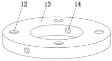
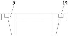
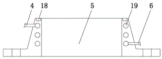
In the figure: 1. a first screw; 2. a third screw; 3. a moving ring; 4. a feed pipe; 5. a stationary ring; 6. a discharge pipe; 7. a stationary ring seat; 8. a spring pressing seat; 9. a strong spring; 10. a second screw; 11. a rotating shaft; 12. a second threaded hole; 13. a spring seat; 14. a first threaded hole; 15. a third threaded hole; 16. a gasket; 17. a fourth threaded hole; 18. a wear-resistant seal ring; 19. a cavity.
Detailed Description
The technical solutions in the embodiments of the present invention will be described clearly and completely with reference to the accompanying drawings in the embodiments of the present invention, and it is obvious that the described embodiments are only some embodiments of the present invention, not all embodiments. Based on the embodiments in the present invention, all other embodiments obtained by a person skilled in the art without creative work belong to the protection scope of the present invention.
As shown in fig. 1-5, the utility model provides a technical solution: a sealing structure of a wear-resistant mechanical end face comprises a rotating shaft 11, a spring seat 13 is sleeved outside the rotating shaft 11, a spring pressing seat 8 is arranged outside the rotating shaft 11 in a sleeved mode, the spring seat 13 is located above the spring pressing seat 8, two symmetrical first threaded holes 14 are formed in the outer surface of the spring seat 13, a first screw 1 is connected to the inner portion of each first threaded hole 14 in a threaded mode, the spring seat 13 is circumferentially fixed with the rotating shaft 11 through the first screw 1, second threaded holes 12 which are arranged equidistantly are formed in the upper surface of the spring seat 13 in a fixed mode, third threaded holes 15 which are arranged equidistantly are formed in the upper surface of the spring pressing seat 8 in a fixed mode, a second screw 10 is connected to the inner portion of each second threaded hole 12 in a threaded mode, the bottom end of each second screw 10 is in threaded connection with the corresponding third threaded hole 15, a powerful spring 9 is sleeved outside, the top end and the bottom end of the strong spring 9 are respectively contacted with one side surface of the spring seat 13 and the spring pressing seat 8 which are close to each other, the rotating ring 3 is sleeved outside the rotating shaft 11, the bottom end of the spring pressing seat 8 is clamped with the inner part of the movable ring 3, the outer surface of the movable ring 3 is provided with fourth threaded holes 17, the inner part of each fourth threaded hole 17 is in threaded connection with a third screw 2, the movable ring 3 is circumferentially fixed with a spring pressing seat 8 through a third screw 2, a static ring seat 7 is sleeved outside the rotating shaft 11, a static ring 5 is fixedly arranged inside the static ring seat 7, the static ring 5 is contacted with the dynamic ring 3, a spiral cavity 19 is arranged inside the static ring 5, a feeding pipe 4 is arranged outside the static ring 5, and the right end of the feeding pipe 4 penetrates through the outer surface of the static ring 5 and extends to the inside of the cavity 19, the discharge pipe 6 is arranged outside the static ring 5, and the left end of the discharge pipe 6 penetrates through the outer surface of the static ring 5 and extends to the inside of the cavity 19.
Further, a sealing gasket 16 is arranged inside the movable ring 3, and the bottom surface of the spring pressing seat 8 is in contact with the sealing gasket 16. The sealing performance between the spring pressing seat 8 and the movable ring 3 is improved, and external garbage is prevented from entering the joint of the spring pressing seat 8 and the movable ring 3 to affect use.
Further, a wear-resistant sealing ring 18 is fixedly embedded on the upper surface of the static ring 5. The design that the wear-resistant sealing ring 18 is arranged between the moving ring 3 and the static ring 5 effectively improves the wear-resistant performance of the static ring 5 and prolongs the service life of the static ring 5.
Furthermore, the movable ring 3 and the static ring 5 are sealed by end faces.
The working principle is as follows: when axis of rotation 11 begins to rotate, the rotatory drive of spring holder 13 with axis of rotation 11 fixed connection drives spring pressure seat 8 and rotates under the effect of quiet ring 5, under the effect of powerful spring 9 elasticity, make movable ring 3 tightly press on quiet ring 5, and quiet ring 5 is motionless, rotate as movable ring 3 and rub for a long time with quiet ring 5 terminal surface, let in the coolant liquid from inlet pipe 4 and get into quiet ring 5 inside and arrange material pipe 6 and discharge from arranging, the coolant liquid absorbs the temperature that the conduction reduced quiet ring 5 to the heat of quiet ring 5 inside, and the heat that movable ring 3 rotated the production absorbs the high temperature that the conduction produced to the heat through movable ring 3 conduction to quiet ring 5 coolant liquid, avoid between movable ring 3 and the quiet ring 5 temperature rise to lead to lubricated vaporization to cause dry friction to make its friction aggravation, improved its antifriction performance.
It should be noted that, in this document, the terms "center", "upper", "lower", "left", "right", "vertical", "horizontal", "inner", "outer", etc. indicate orientations or positional relationships based on the orientations or positional relationships shown in the drawings, and are only for convenience of description and simplification of description, but do not indicate or imply that the referred device or element must have a specific orientation, be constructed in a specific orientation, and be operated, and thus, should not be construed as limiting the present invention; the terms "first," "second," and "third" are used for descriptive purposes only and are not to be construed as indicating or implying relative importance, and furthermore, unless otherwise explicitly stated or limited, the terms "fixedly," "mounted," "connected," and "connected" are to be construed broadly, e.g., "mounted" may be fixedly connected, or detachably connected, or integrally connected; "connected" may be mechanically or electrically connected; "connected" may be directly connected or indirectly connected through an intermediate member, or may be internal or external to two elements. The specific meaning of the above terms in the present invention can be understood in specific cases to those skilled in the art.
Although embodiments of the present invention have been shown and described, it will be appreciated by those skilled in the art that changes, modifications, substitutions and alterations can be made in these embodiments without departing from the principles and spirit of the invention, the scope of which is defined in the appended claims and their equivalents.
Claims (4)
1. A seal structure of wear-resisting type machinery terminal surface, includes axis of rotation (11), its characterized in that: the spring pressing device is characterized in that a spring seat (13) is sleeved outside the rotating shaft (11), a spring pressing seat (8) is sleeved outside the rotating shaft (11), the spring seat (13) is located above the spring pressing seat (8), two symmetrical first threaded holes (14) are formed in the outer surface of the spring seat (13), first screws (1) are connected to the inner portions of the first threaded holes (14) in a threaded mode, the spring seat (13) is circumferentially fixed to the rotating shaft (11) through the first screws (1), second threaded holes (12) which are arranged at equal intervals are formed in the upper surface of the spring seat (13) in a fixed mode, third threaded holes (15) which are arranged at equal intervals are formed in the upper surface of the spring pressing seat (8), second screws (10) are connected to the inner threads of the second threaded holes (12), and the bottom end of each second screw (10) is in threaded connection with the corresponding third threaded hole (15), every the outside of second screw (10) all overlaps and is equipped with powerful spring (9), and the top and the bottom of powerful spring (9) respectively with spring holder (13) and the spring press a side of seat (8) to be close to each other to contact, the outside cover of axis of rotation (11) is equipped with rotating ring (3), and the spring presses the bottom joint of seat (8) and the inside of rotating ring (3), fourth screw hole (17) have been seted up to the surface of rotating ring (3), every the equal threaded connection in inside of fourth screw hole (17) has third screw (2), and rotating ring (3) carry out circumference through third screw (2) and spring press seat (8) and fix, the outside cover of axis of rotation (11) is equipped with stationary ring seat (7), the inside fixed mounting of stationary ring seat (7) has stationary ring (5), and stationary ring (5) and rotating ring (3) contact, the inside of stationary ring (5) is seted up and is spiral helicine cavity (19), the outside of quiet ring (5) is provided with inlet pipe (4), and the right-hand member of inlet pipe (4) runs through the surface of quiet ring (5) and extends to the inside of cavity (19), the outside of quiet ring (5) is provided with row material pipe (6), and arranges the inside that the left end of material pipe (6) runs through the surface of quiet ring (5) and extends to cavity (19).
2. A wear-resistant mechanical end face seal according to claim 1, wherein: a sealing gasket (16) is arranged in the movable ring (3), and the bottom surface of the spring pressing seat (8) is in contact with the sealing gasket (16).
3. A wear-resistant mechanical end face seal according to claim 1, wherein: and a wear-resistant sealing ring (18) is fixedly embedded on the upper surface of the static ring (5).
4. A wear-resistant mechanical end face seal according to claim 1, wherein: the movable ring (3) and the static ring (5) are sealed at end faces.
Priority Applications (1)
| Application Number | Priority Date | Filing Date | Title |
|---|---|---|---|
| CN202020523661.3U CN212155810U (en) | 2020-04-11 | 2020-04-11 | Sealing structure of wear-resistant mechanical end face |
Applications Claiming Priority (1)
| Application Number | Priority Date | Filing Date | Title |
|---|---|---|---|
| CN202020523661.3U CN212155810U (en) | 2020-04-11 | 2020-04-11 | Sealing structure of wear-resistant mechanical end face |
Publications (1)
| Publication Number | Publication Date |
|---|---|
| CN212155810U true CN212155810U (en) | 2020-12-15 |
Family
ID=73719402
Family Applications (1)
| Application Number | Title | Priority Date | Filing Date |
|---|---|---|---|
| CN202020523661.3U Active CN212155810U (en) | 2020-04-11 | 2020-04-11 | Sealing structure of wear-resistant mechanical end face |
Country Status (1)
| Country | Link |
|---|---|
| CN (1) | CN212155810U (en) |
-
2020
- 2020-04-11 CN CN202020523661.3U patent/CN212155810U/en active Active
Similar Documents
| Publication | Publication Date | Title |
|---|---|---|
| CN100370146C (en) | Mechaniclly sealing device of immersible pump | |
| CN212155810U (en) | Sealing structure of wear-resistant mechanical end face | |
| CN212360780U (en) | Anti-vibration mechanical sealing element | |
| CN114483958B (en) | Sealing mechanism with lubrication movement | |
| CN107401617B (en) | Combined sealing device for rotating shaft | |
| CN113154043B (en) | Sealing device combining mechanical seal and magnetic liquid seal | |
| CN212004240U (en) | Shaft end sealing device | |
| US20220221061A1 (en) | Magnetic liquid sealing device | |
| CN216894858U (en) | Mechanical sealing structure for high-temperature oil pump | |
| CN213628875U (en) | Low-abrasion mechanical seal | |
| CN219159241U (en) | Corrosion-resistant and particle-resistant chemical pump sealing device | |
| CN208330828U (en) | Machinery sealed device of impurity pump | |
| CN212251140U (en) | Mechanical sealing device convenient to maintain | |
| CN215720835U (en) | Radial double-end-face fulcrum type mechanical seal special for integrated stirring | |
| CN212717350U (en) | Mechanical sealing device for chloroprene emulsion emulsification pump | |
| CN210510290U (en) | High stability bearing seal structure | |
| CN217328456U (en) | Split mechanical seal | |
| CN212745054U (en) | Double-end-face fluorine machine seal | |
| CN218063387U (en) | Novel high-rotation-speed integrated mechanical sealing structure | |
| CN218564397U (en) | KL106U mechanical seal improved structure device | |
| CN213479453U (en) | Simple structure's anti-dress formula spherical seal structure | |
| CN214742314U (en) | Chemical pump sealing device | |
| CN215334340U (en) | Shaft sealing structure of speed reducer for stirring | |
| CN212804703U (en) | High-pressure high-speed rotary sealing device for engineering machinery | |
| CN217502575U (en) | Friction sealing structure device |
Legal Events
| Date | Code | Title | Description |
|---|---|---|---|
| GR01 | Patent grant | ||
| GR01 | Patent grant |