CN212155075U - Multi-station liquid injection pump - Google Patents
Multi-station liquid injection pump Download PDFInfo
- Publication number
- CN212155075U CN212155075U CN202020791790.0U CN202020791790U CN212155075U CN 212155075 U CN212155075 U CN 212155075U CN 202020791790 U CN202020791790 U CN 202020791790U CN 212155075 U CN212155075 U CN 212155075U
- Authority
- CN
- China
- Prior art keywords
- ceramic
- piston
- motor
- pump body
- bottom plate
- Prior art date
- Legal status (The legal status is an assumption and is not a legal conclusion. Google has not performed a legal analysis and makes no representation as to the accuracy of the status listed.)
- Active
Links
Images


Landscapes
- Reciprocating Pumps (AREA)
Abstract
The utility model discloses a multi-station liquid injection pump, which comprises a first motor, a sliding table, a bottom plate, a second motor, a ceramic piston and a ceramic pump body; the first motor is arranged on the bottom plate and drives the sliding table to do linear reciprocating motion in a screw rod transmission mode; the plurality of second motors are arranged on the sliding table; an output shaft of each second motor is fixedly connected with one end part of one ceramic piston; the other end part of each ceramic piston is provided with a flow limiting part and is movably arranged in the ceramic pump body; all be equipped with on the ceramic pump body with current-limiting portion clearance fit's inlet, liquid outlet, and all the ceramic pump body all fixed mounting be in on the bottom plate. The utility model has the advantages of simple structure, high liquid injection amount precision, small occupied space, convenient adjustment and the like.
Description
Technical Field
The utility model belongs to the technical field of the infusion pump technique and specifically relates to a multistation infusion pump.
Background
The liquid injection pump mainly drives a piston to do linear reciprocating motion in a pump body through a power device, so that the volume of a sealed working cavity enclosed by the interior of the pump body and the piston is changed to realize liquid absorption and injection operation, and the liquid injection pump is widely applied to different fields of pharmacy, biological reagents, petrochemical industry and the like; in the field of lithium battery manufacturing, a liquid injection pump is an important device in automatic liquid injection operation of a lithium battery, and in the existing lithium battery liquid injection pump, a piston is usually driven by a power device to make linear reciprocating motion in a corresponding pump body, namely, only one liquid injection station is arranged in one liquid injection pump; in order to improve the speed of annotating the liquid operation in the lithium cell production process, need a plurality of notes liquid stations to carry out work simultaneously, if directly adopt multiunit infusion pump simultaneous working, not only whole cost is high, still occupies production space too big, need adjust every infusion pump one by one when required notes liquid volume changes moreover, the operation is comparatively loaded down with trivial details.
Therefore, there is a need for a multi-position liquid-filling pump that uses a power device to drive a plurality of pistons to reciprocate linearly in corresponding pump bodies.
SUMMERY OF THE UTILITY MODEL
The utility model provides a technical problem provide a multistation liquid filling pump to the problem among the above-mentioned prior art, this multistation liquid filling pump can be by a power device a plurality of pistons of simultaneous drive do straight reciprocating motion in the pump body that corresponds.
In order to solve the technical problem, the utility model adopts a technical proposal that the multi-station liquid injection pump comprises a first motor, a sliding table, a bottom plate, a second motor, a ceramic piston and a ceramic pump body; the first motor is arranged on the bottom plate and drives the sliding table to do linear reciprocating motion in a screw rod transmission mode; the plurality of second motors are arranged on the sliding table; an output shaft of each second motor is fixedly connected with one end part of one ceramic piston; the other end part of each ceramic piston is provided with a flow limiting part and is movably arranged in the ceramic pump body; all be equipped with on the ceramic pump body with current-limiting portion clearance fit's inlet, liquid outlet, and all the ceramic pump body all fixed mounting be in on the bottom plate.
As a further elaboration of the above technical solution:
in the technical scheme, the device also comprises a screw rod, a screw rod nut and a connecting plate; the first motor is fixedly arranged at the lower part of the bottom plate, and the screw rod is connected with an output shaft of the first motor; the screw rod nut is in threaded fit with the screw rod; the lower end of the connecting plate is fixedly connected with the screw rod nut, and the upper end of the connecting plate is fixedly connected with the sliding table; the sliding table is arranged on the upper part of the bottom plate in a sliding manner; and the bottom plate is provided with a clearance for the connecting plate to move.
In the above technical scheme, the connecting plate is provided with an induction sheet, and the bottom plate is provided with a plurality of first groove-shaped photoelectric sensors matched with the induction sheet along the moving direction of the connecting plate.
In the technical scheme, the ceramic pump body comprises a mounting sleeve, a piston sleeve, a liquid inlet joint and a liquid outlet joint; the mounting sleeve is arranged on the bottom plate; the piston sleeve is fixedly arranged in the mounting sleeve; the liquid inlet joint and the liquid outlet joint are both arranged on the side wall of the mounting sleeve in a penetrating manner; the liquid inlet joint and the piston sleeve are provided with the liquid inlet in a penetrating way; the liquid outlet joint and the piston sleeve are provided with the liquid outlet in a penetrating manner.
In the above technical solution, the mounting sleeve is in a hollow cylinder shape; the mounting sleeve is inwards formed into a limit stop ring towards the end edge of one end of the second motor; the other end of the mounting sleeve is provided with a sealing end cover; the piston sleeve is hollow and cylindrical and is embedded in the mounting sleeve, and two ends of the piston sleeve respectively abut against the limiting baffle ring and the sealing end cover; a first sealing ring is arranged between the piston sleeve and the sealing end cover; a second sealing ring is arranged between the piston sleeve and the liquid inlet joint; and a third sealing ring is arranged between the piston sleeve and the liquid outlet joint.
In the above technical scheme, a vertical plate is arranged on the sliding table, and all the second motors are arranged on the vertical plate; an output shaft of the second motor is fixedly connected with the ceramic piston through a coupler; an induction rod is arranged on the side wall of the coupler; and a second groove-shaped photoelectric sensor matched with the induction rod is arranged on the vertical plate.
In the technical scheme, an annular shoulder is formed at one end, far away from the ceramic pump body, of the ceramic piston; the annular shoulder is inserted into the coupler; the coupler with run through on the annular circular bead and be provided with the fixed pin, the both ends of fixed pin are all installed and are leaned on spacing meson on the coupler lateral wall.
The utility model has the advantages that firstly, the first motor drives the sliding table to slide through the screw rod transmission mode, and the screw rod transmission mode has the advantages of high precision, stable work and high reliability; secondly, the sliding table is driven to slide by one first motor, and the sliding table drives a plurality of groups of second motors and ceramic pistons arranged on the second motors to do linear reciprocating motion in corresponding ceramic pump bodies, compared with the mode that a plurality of groups of liquid injection pumps are directly arranged, the utility model has the advantages of low manufacturing cost, small occupied space, simple and convenient operation and the like; thirdly, the second motor is controlled through an external industrial control system, and an operator can synchronously change the strokes of all ceramic pistons by changing the strokes of the sliding table driven by the second motor through the industrial control system, so that the liquid suction amount or the liquid injection amount of all ceramic pump bodies can be synchronously changed, compared with the method of manually adjusting the liquid injection amount of each liquid injection pump one by one, the utility model has the advantages of simple and convenient operation and higher adjustment accuracy; fourthly, the ceramic pump body and the ceramic piston are made of ceramic materials, have the characteristics of corrosion resistance and high wear resistance, meet the injection requirements of various liquids such as acid, alkali and organic solvents, and have extremely wide application range and long service life; fourthly, the second motor is used for controlling the rotation of the ceramic piston, so that the function of closing the liquid inlet or the liquid outlet of the ceramic pump body by ceramic injection molding can be conveniently realized.
Drawings
Fig. 1 is a perspective view of the present invention;
FIG. 2 is a schematic view of the sliding table and the upper part of the sliding table of the present invention;
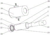
FIG. 3 is a schematic structural view of the ceramic pump body, the ceramic piston and the second motor according to the present invention;
FIG. 4 is a cross-sectional view of the ceramic pump body and the ceramic piston of the present invention;
fig. 5 is an exploded view of the ceramic pump body and the ceramic piston according to the present invention.
Detailed Description
The present invention will be described in further detail with reference to the accompanying drawings.
The embodiments described by referring to the drawings are exemplary and intended to be used for explaining the present application and are not to be construed as limiting the present application. In the description of the present application, it is to be understood that the terms "center," "longitudinal," "lateral," "length," "width," "thickness," "upper," "lower," "front," "rear," "left," "right," "vertical," "horizontal," "top," "bottom," "inner," "outer," "clockwise," "counterclockwise," and the like are used in the orientations and positional relationships indicated in the drawings for convenience in describing the present application and for simplicity in description, and are not intended to indicate or imply that the referenced devices or elements must have a particular orientation, be constructed in a particular orientation, and be operated in a particular manner, and thus should not be considered limiting. Furthermore, the terms "first", "second" and "first" are used for descriptive purposes only and are not to be construed as indicating or implying relative importance or implicitly indicating the number of technical features indicated. Thus, a feature defined as "first" or "second" may explicitly or implicitly include one or more of that feature. In the description of the present application, "a plurality" means two or more unless specifically limited otherwise. In this application, unless expressly stated or limited otherwise, the terms "mounted," "connected," "secured," and the like are to be construed broadly and can include, for example, fixed connections, removable connections, or integral connections; can be mechanically or electrically connected; they may be connected directly or indirectly through intervening media, or they may be interconnected between two elements. The specific meaning of the above terms in the present application can be understood by those of ordinary skill in the art as appropriate. In this application, unless expressly stated or limited otherwise, the first feature "on" or "under" the second feature may comprise direct contact of the first and second features, or may comprise contact of the first and second features not directly but through another feature in between. Also, the first feature being "on," "above" and "over" the second feature includes the first feature being directly on and obliquely above the second feature, or merely indicating that the first feature is at a higher level than the second feature. A first feature being "under," "below," and "beneath" a second feature includes the first feature being directly above and obliquely above the second feature, or simply meaning that the first feature is at a lesser level than the second feature.
Fig. 1-5 illustrate a multi-position infusion pump according to an embodiment of the present invention, and referring to fig. 1-5, a multi-position infusion pump includes a first motor 1, a sliding table 2, a bottom plate 3, a second motor 4, a ceramic piston 5 and a ceramic pump body 6. The first motor 1 is arranged on the bottom plate 3 and drives the sliding table 2 to do linear reciprocating motion in a screw rod transmission mode, wherein the first motor 1 is a stepping motor. A plurality of second motors 4 are arranged on the sliding table 3, and an output shaft of each second motor 4 is connected with one ceramic piston 5; each ceramic piston 5 is movably sleeved with one ceramic pump body 6; all be equipped with inlet and liquid outlet on the ceramic pump body 6, ceramic piston 5 inserts ceramic pump body 6's one end shaping has and is used for closing the inlet or the current-limiting part 7 of liquid outlet, specifically speaking, by second motor 4 drive ceramic piston 5 is rotatory ceramic piston 5 rotatory in-process ceramic piston 5 rotatory current-limiting part 7 will the inlet with the sealed work appearance chamber of the inside of ceramic pump body 6 cuts off or will the liquid outlet with the sealed work appearance chamber of the inside of ceramic pump body 6 cuts off. All the ceramic pump bodies 6 are mounted on the base plate 3.
Further, the utility model discloses still include lead screw 9, screw-nut 10 and connecting plate 11. The first motor 1 is fixedly arranged at the lower part of the bottom plate 3; the screw rod 9 is connected with an output shaft of the first motor 1; the screw rod nut 10 is in threaded fit with the screw rod 9; the lower end of the connecting plate 11 is fixedly connected with the screw rod nut 10, and the upper end of the connecting plate 11 is fixedly connected with the sliding table 2; a sliding block 14 is arranged at the lower part of the sliding table 2, and a sliding rail 15 which is in sliding fit with the sliding block 14 is arranged at the upper part of the bottom plate 3; and the bottom plate 3 is provided with a clearance for the movement of the connecting plate 11. The connecting plate 11 is also provided with an induction sheet 12, and the bottom plate 3 is provided with a plurality of first groove-shaped photoelectric sensors 13 matched with the induction sheet 12 along the moving direction of the connecting plate 11; in this embodiment, first motor 1 is step motor, adopts step motor cooperation lead screw transmission drive the gliding mode of slip table 2 compares in the cylinder drive the gliding mode of slip table 2 has the advantage that transmission precision is high. When the automatic screw rod driving device works, the first motor 8 is connected to an external power supply and drives the screw rod 9 to rotate, and the screw rod nut 10, the connecting plate 11 and the sliding table 2 are driven to synchronously perform linear reciprocating motion in the rotating process of the screw rod 9; simultaneously, response piece 12 is followed connecting plate 11 is linear reciprocating motion in step, response piece 12 is by a plurality of in-process in the motion first cell type photoelectric sensor 13 judges response piece 12's position, and then judge whether the stroke of slip table 2 is correct, finally can judge ceramic piston 5 is in whether the stroke in the ceramic pump body 6 is correct, cooperates external industry control system, can reach real-time accurate control ceramic piston 5 with the purpose of the liquid volume is inhaled to the ceramic pump body 6 and annotates the liquid volume.
Further, the ceramic pump body 6 comprises a mounting sleeve 16, a piston sleeve 17, a liquid inlet joint 18 and a liquid outlet joint 19. The mounting sleeve 16 is arranged on the bottom plate 3; the piston sleeve 17 is fixedly arranged in the mounting sleeve 16; the liquid inlet joint 18 and the liquid outlet joint 19 are both arranged on the side wall of the mounting sleeve 16 in a penetrating manner; in this embodiment, the liquid inlet joint 18 and the liquid outlet joint 19 are both screwed on the mounting sleeve 16, and during maintenance, the liquid inlet joint 18 or the liquid outlet joint 19 to be replaced is directly screwed in or out, which has the advantage of easy assembly and disassembly. The liquid inlet joint 18 and the piston sleeve 17 are provided with the liquid inlet in a penetrating way; the liquid outlet is arranged on the liquid outlet joint 19 and the piston sleeve 17 in a penetrating way. In this embodiment, the installation sleeve 16, the piston sleeve 17, the liquid inlet joint 18 and the liquid outlet joint 19 are all made of high-performance industrial ceramics, such as alumina ceramics and silicon carbide ceramics, and have the characteristics of corrosion resistance and high wear resistance, and meet the injection requirements of various liquids such as acidity, alkalinity and organic solvents, and have extremely wide application range and long service life; simultaneously, because the solution corrosivity and the toxicity of lithium cell are all high, and the utility model discloses in the ceramic pump body 6 adopts bilayer structure, has guaranteed also difficult direct leaking into external under the condition that the weeping appears in piston bush 17.
Further, the mounting sleeve 16 is hollow and cylindrical; the end edge of one end of the mounting sleeve 16 facing the second motor 4 is inwards formed with a limit stop ring 20; the other end of the mounting sleeve 16 is screwed with a sealing end cover 21, and a sealing baffle 22 made of ceramic materials is embedded on the side wall of the sealing end cover facing the limit baffle ring 20; the piston sleeve 17 is hollow and cylindrical and is nested in the mounting sleeve 16; the outer wall of the piston sleeve 17 is tightly matched with the inner wall of the mounting sleeve 16, and the piston sleeve and the mounting sleeve are limited to rotate relatively in a key connection mode; the two ends of the piston sleeve 17 respectively abut against the limit stop ring 20 and the sealing baffle 22, and now the piston sleeve 17 and the mounting sleeve 16 are displaced relatively. Piston sleeve 17 with be equipped with first sealing washer 23 between the seal baffle 22, specifically speaking, seal baffle 22 orientation it is right to be equipped with first ring channel on the lateral wall of piston sleeve 17 be used for first sealing washer 23 advance line location, prevent first sealing washer 23 off tracking improves seal baffle with seal effect between the piston sleeve 17. Piston bush 17 with be equipped with second sealing washer 24 between the liquid inlet joint 18, specifically speaking, liquid inlet joint 18 orientation it is right to be equipped with the second annular groove on the lateral wall of piston bush 17 be used for second sealing washer 24 fixes a position, prevents 24 off tracking of second sealing washer, and then prevents piston bush 17 with there is the gap to lead to in liquid inlet complex department the inlet weeping. A third sealing ring 25 is arranged between the piston sleeve 17 and the liquid outlet joint 19, specifically, a third annular groove is arranged on the side wall of the liquid outlet joint 19 facing the piston sleeve 17 and used for positioning the third sealing ring 25 to prevent the third sealing ring 25 from deviating, so that a gap is formed at the matching position of the piston sleeve 17 and the liquid outlet joint 19 to prevent the liquid outlet from leaking. Simultaneously, piston sleeve 17 is close to the inner wall of the one end of second motor 4 is equipped with fourth annular groove 26, fourth annular groove 26 is used for installing the fourth sealing washer, because ceramic piston 5 with what piston sleeve 17 adopted is clearance fit, in order to prevent ceramic piston 5 with there is lithium cell solution to ooze in the slight clearance between the piston sleeve 17, adopt the fourth sealing washer can to piston sleeve 17 with ceramic piston 5 plays fine sealed effect.
Further, a vertical plate 27 is arranged on the sliding table 2, and all the second motors 4 are arranged on the vertical plate 27; an output shaft of the second motor 4 is fixedly connected with the ceramic piston 5 through a coupling 28; an induction rod 29 is arranged on the side wall of the coupler 28; two second groove-shaped photoelectric sensors 30 matched with the induction rod 29 are symmetrically arranged on the vertical plate 27 along the circumferential direction of the coupler 28, and whether the rotation angle of the ceramic piston 5 is accurate or not, namely whether the liquid inlet or the liquid outlet is accurately closed or not can be detected by judging whether the induction rod 29 reaches the two second groove-shaped photoelectric sensors 30 or not.
Further, an annular shoulder 31 is formed at one end of the ceramic piston 5 away from the ceramic pump body 6; said annular shoulder being inserted in said coupling 28; the shaft coupling 28 with it is provided with the fixed pin to run through on the annular circular bead, the both ends of fixed pin are installed respectively and are leaned on the spacing meson on the shaft coupling lateral wall.
The working principle of the utility model is as follows:
the first step, imbibition. Firstly, in an initial state, the flow restriction portion 7 of the ceramic piston 5 separates the liquid outlet from the sealed working cavity inside the ceramic pump body 6, and the liquid inlet is communicated with the sealed working cavity inside the ceramic pump body 6; then, the power device 1 drives the sliding table 2, the second motor 4 and the ceramic piston 5 to synchronously move in a direction away from the ceramic pump body 6; finally, the volume of the sealed working cavity between the ceramic pump body 6 and the ceramic piston 5 is increased to form a negative pressure, and the outside solution is sucked into the ceramic pump body 6 through the liquid inlet.
And secondly, injecting liquid. Firstly, the second motor 4 drives the ceramic piston 5 to rotate, so that the liquid inlet is separated from the sealed working cavity inside the ceramic pump body 6 by the flow limiting part 7 of the ceramic piston 5, and the liquid outlet is communicated with the sealed working cavity inside the ceramic pump body 6; then, the power device 1 drives the sliding table 2, the second motor 4 and the ceramic piston 5 to synchronously move towards the direction close to the ceramic pump body 6; finally, the ceramic piston 5 discharges the liquid inside the ceramic pump body 6 along the liquid outlet.
The above is not intended to limit the technical scope of the present invention, and any modifications, equivalent changes and modifications made to the above embodiments according to the technical spirit of the present invention are all within the scope of the technical solution of the present invention.
Claims (7)
1. A multi-station liquid injection pump is characterized by comprising a first motor, a sliding table, a bottom plate, a second motor, a ceramic piston and a ceramic pump body; the first motor is arranged on the bottom plate and drives the sliding table to do linear reciprocating motion in a screw rod transmission mode; the plurality of second motors are arranged on the sliding table; an output shaft of each second motor is fixedly connected with one end part of one ceramic piston; the other end part of each ceramic piston is provided with a flow limiting part and is movably arranged in the ceramic pump body; all be equipped with on the ceramic pump body with current-limiting portion clearance fit's inlet, liquid outlet, and all the ceramic pump body all fixed mounting be in on the bottom plate.
2. The multi-station liquid injection pump as claimed in claim 1, further comprising a screw rod, a screw nut and a connecting plate; the first motor is fixedly arranged at the lower part of the bottom plate, and the screw rod is connected with an output shaft of the first motor; the screw rod nut is in threaded fit with the screw rod; the lower end of the connecting plate is fixedly connected with the screw rod nut, and the upper end of the connecting plate is fixedly connected with the sliding table; the sliding table is arranged on the upper part of the bottom plate in a sliding manner; and the bottom plate is provided with a clearance for the connecting plate to move.
3. The multi-station liquid injection pump as claimed in claim 2, wherein the connecting plate is provided with a sensing piece, and the bottom plate is provided with a plurality of first groove-shaped photoelectric sensors engaged with the sensing piece along the moving direction of the connecting plate.
4. The multi-station liquid injection pump as claimed in claim 1, wherein the ceramic pump body comprises a mounting sleeve, a piston sleeve, a liquid inlet joint and a liquid outlet joint; the mounting sleeve is arranged on the bottom plate; the piston sleeve is fixedly arranged in the mounting sleeve; the liquid inlet joint and the liquid outlet joint are both arranged on the side wall of the mounting sleeve in a penetrating manner; the liquid inlet joint and the piston sleeve are provided with the liquid inlet in a penetrating way; the liquid outlet joint and the piston sleeve are provided with the liquid outlet in a penetrating manner.
5. The multi-station liquid injection pump as claimed in claim 4, wherein the mounting sleeve is hollow and cylindrical; the mounting sleeve is inwards formed into a limit stop ring towards the end edge of one end of the second motor; the other end of the mounting sleeve is provided with a sealing end cover; the piston sleeve is hollow and cylindrical and is embedded in the mounting sleeve, and two ends of the piston sleeve respectively abut against the limiting baffle ring and the sealing end cover; a first sealing ring is arranged between the piston sleeve and the sealing end cover; a second sealing ring is arranged between the piston sleeve and the liquid inlet joint; and a third sealing ring is arranged between the piston sleeve and the liquid outlet joint.
6. The multi-station liquid injection pump as claimed in any one of claims 1 to 5, wherein a vertical plate is arranged on the sliding table, and all the second motors are arranged on the vertical plate; an output shaft of the second motor is fixedly connected with the ceramic piston through a coupler; an induction rod is arranged on the side wall of the coupler; and a second groove-shaped photoelectric sensor matched with the induction rod is arranged on the vertical plate.
7. The multi-station liquid injection pump as claimed in claim 6, wherein an annular shoulder is formed at one end of the ceramic piston away from the ceramic pump body; the annular shoulder is inserted into the coupler; the coupler with run through on the annular circular bead and be provided with the fixed pin, the both ends of fixed pin are all installed and are leaned on spacing meson on the coupler lateral wall.
Priority Applications (1)
| Application Number | Priority Date | Filing Date | Title |
|---|---|---|---|
| CN202020791790.0U CN212155075U (en) | 2020-05-14 | 2020-05-14 | Multi-station liquid injection pump |
Applications Claiming Priority (1)
| Application Number | Priority Date | Filing Date | Title |
|---|---|---|---|
| CN202020791790.0U CN212155075U (en) | 2020-05-14 | 2020-05-14 | Multi-station liquid injection pump |
Publications (1)
| Publication Number | Publication Date |
|---|---|
| CN212155075U true CN212155075U (en) | 2020-12-15 |
Family
ID=73710558
Family Applications (1)
| Application Number | Title | Priority Date | Filing Date |
|---|---|---|---|
| CN202020791790.0U Active CN212155075U (en) | 2020-05-14 | 2020-05-14 | Multi-station liquid injection pump |
Country Status (1)
| Country | Link |
|---|---|
| CN (1) | CN212155075U (en) |
Cited By (1)
| Publication number | Priority date | Publication date | Assignee | Title |
|---|---|---|---|---|
| CN114122640A (en) * | 2021-10-22 | 2022-03-01 | 深圳市迪瑞达自动化有限公司 | Four-head linear variable pump |
-
2020
- 2020-05-14 CN CN202020791790.0U patent/CN212155075U/en active Active
Cited By (1)
| Publication number | Priority date | Publication date | Assignee | Title |
|---|---|---|---|---|
| CN114122640A (en) * | 2021-10-22 | 2022-03-01 | 深圳市迪瑞达自动化有限公司 | Four-head linear variable pump |
Similar Documents
| Publication | Publication Date | Title |
|---|---|---|
| KR101423809B1 (en) | Metering pump and its drving device | |
| CN212155075U (en) | Multi-station liquid injection pump | |
| CN101865101A (en) | Inclined-axis rotation type axial plunger pump | |
| CN105840446A (en) | High-precision metering pump | |
| CN208502967U (en) | A kind of quantitative plunger pump | |
| CN114206503B (en) | Mechanism for electronically regulating flow in a fixed displacement pump | |
| CN111594420A (en) | Diaphragm pump with suction and lift | |
| CN216044232U (en) | Plunger pump | |
| CN201013549Y (en) | Metering pump | |
| CN114542427B (en) | Zero suction pressure head cryogenic liquid pump | |
| CN206845435U (en) | A kind of linear high precision peristaltic pump | |
| CN111828292B (en) | Measuring pump with adjustable measuring range | |
| US6467655B1 (en) | Pump dispenser | |
| CN210977789U (en) | Reciprocating linkage single-cam plunger pump | |
| CN112108198A (en) | Double-discharge high-precision piston type liquid-transfering gun | |
| CN219101544U (en) | Metering mechanical diaphragm pump | |
| CN101876304A (en) | Corrugated pipe metering pump | |
| CN107676250B (en) | Reciprocating injection pump | |
| CN210977788U (en) | Reciprocating linkage double-cam plunger pump | |
| CN220599951U (en) | Linear metering pump and automatic filling equipment | |
| CN220769683U (en) | Peristaltic pump head | |
| CN219317124U (en) | Reciprocating flow pump | |
| CN219733576U (en) | Quantitative metering pump | |
| CN220066065U (en) | Single-shaft liquid injection machine | |
| CN211875236U (en) | Axial-flow plunger precise control regulating valve |
Legal Events
| Date | Code | Title | Description |
|---|---|---|---|
| GR01 | Patent grant | ||
| GR01 | Patent grant |