Material mixing device
Technical Field
The utility model relates to a mixing arrangement technical field specifically is a material mixing device.
Background
The compound microbial agent is a microbial agent prepared from two or more than two microbial strains which are not antagonistic to each other. The microbial inoculum generally has the excellent characteristics of complete species, reasonable compatibility, strong functionality, high economic benefit and the like, and the composite microbial liquid microbial inoculum is mostly prepared by mixing and stirring a plurality of microbial liquid microbial inocula in proportion at present.
The existing material mixing device for the compound microbial inoculant has the problem of insufficient mixing, the quality of the produced compound microbial inoculant cannot be guaranteed, and the benefit of enterprises is further influenced.
SUMMERY OF THE UTILITY MODEL
An object of the utility model is to provide a material mixing device to solve the problem that proposes among the above-mentioned background art.
In order to achieve the above object, the utility model provides a following technical scheme: the utility model provides a material mixing device, includes mixing box and fly leaf, the last fixed surface of mixing box is connected with the motor case, the internally mounted of motor case has servo motor, servo motor's output fixedly connected with transmission, the inside sliding connection of mixing box has the fly leaf, the fly leaf upper surface rotates and is connected with rotating device, rotating device and transmission sliding connection, the below symmetry of fly leaf has put the stirring post, the fixed surface of stirring post is connected with a plurality of puddlers, the one end and the rotating device fixed connection of mixing box inner chamber bottom are kept away from to the stirring post, the stirring post rotates with the fly leaf and is connected.
Preferably, transmission includes initiative bevel gear, driven bevel gear, spliced pole, disc, connecting block, transmission post and transfer line, servo motor's output fixedly connected with initiative bevel gear, the below symmetry meshing of initiative bevel gear is connected with driven bevel gear, driven bevel gear's fixed surface is connected with the spliced pole, driven bevel gear's one end fixedly connected with disc is kept away from to the spliced pole, disc fixed surface is connected with the connecting block, the rotation of surface of connecting block is connected with the transmission post, the one end that the connecting block was kept away from to the transmission post is rotated with the fly leaf and is connected, initiative bevel gear's fixed surface is connected with the transfer line, the transfer line rotates with the mixing box and is connected.
Preferably, rotating device is including rotating post, rack, drive gear and driven gear, the surperficial sliding connection of transfer line has the rotation post, the fixed surface who rotates the post is connected with a plurality of racks, the upper surface symmetry rotation of fly leaf is connected with drive gear, the drive gear is connected with the rack meshing, drive gear's outside meshing is connected with driven gear, driven gear and stirring post fixed connection.
Preferably, the upper end face of the rotating column is provided with a sliding groove, the sliding groove is a prismatic groove, and the sliding groove is in sliding connection with the transmission rod.
Preferably, the surface of the mixing box is symmetrically provided with feed inlets, and the feed inlets are internally provided with feed valves.
Preferably, the bottom of the mixing box is provided with a discharge port, and a discharge valve is arranged in the discharge port.
Preferably, the surface mounting of mixing box has the controller, servo motor, bleeder valve and feed valve all pass through the wire with the controller and are connected.
Preferably, the upper surface symmetry fixedly connected with support column of mixing box, the one end and the spliced pole rotation connection of mixing box are kept away from to the support column.
Compared with the prior art, the beneficial effects of the utility model are that:
1. the utility model opens the feeding valve, closes the discharging valve to feed the material into the mixing box through the feeding port, can adopt the spiral feeding rod to feed the material, simultaneously starts the servo motor, converts the electric energy into the mechanical energy, drives the driving bevel gear to rotate, further drives the driven bevel gear connected with the driving bevel gear in a meshing way to rotate, further drives the two connecting columns to rotate, the rotation of the connecting columns drives the disc to rotate by taking the connecting columns as the shaft, the disc rotates to drive the connecting block to do the circular motion, further drives the transmission column connected with the disc to move up and down, further drives the movable plate to move up and down, the driving bevel gear rotates, the transmission rod rotates to drive the rotation column to rotate, the rotation column rotates to drive the driven gear and the transmission gear to rotate, the stirring column is fixedly connected with the driven gear, further drives the stirring rod to rotate, stir the material, when the stirring, the stirring device moves up and down along with the movement of the movable plate, so that the stirring effect is better, the stirring efficiency is further improved, the quality of the produced composite microbial agent is ensured, and after the stirring is finished, the discharge valve is opened for discharging;
2. the utility model discloses the connecting block is put the lower on the disc surface when, and the movable rod can not separate with the spout, and the support column carries on spacingly to the spliced pole, guarantees that the carousel rotates the stability when driving the transmission post and reciprocate, compact structure, and the controller is by the accurate control of computer or other control terminal.
Drawings
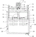
FIG. 1 is a schematic view of the overall structure of the present invention;
FIG. 2 is a schematic view of the structure of the rotating device of the present invention;
FIG. 3 is a schematic view of the transmission device of the present invention;
FIG. 4 is a schematic diagram of the movable plate structure of the present invention;
fig. 5 is a schematic view of the sliding chute structure of the present invention.
In the figure: 1. a mixing box; 2. a movable plate; 3. a motor case; 4. a servo motor; 5. a transmission device; 6. a rotating device; 7. a stirring column; 8. a stirring rod; 9. a drive bevel gear; 10. a driven bevel gear; 11. connecting columns; 12. a disc; 13. connecting blocks; 14. a drive post; 15. a transmission rod; 16. rotating the column; 17. a rack; 18. a transmission gear; 19. a driven gear; 20. a chute; 21. a feed inlet; 22. a feed valve; 23. a discharge port; 24. a discharge valve; 25. a controller; 26. and (4) a support column.
Detailed Description
The technical solutions in the embodiments of the present invention will be described clearly and completely with reference to the accompanying drawings in the embodiments of the present invention, and it is obvious that the described embodiments are only some embodiments of the present invention, not all embodiments. Based on the embodiments in the present invention, all other embodiments obtained by a person skilled in the art without creative work belong to the protection scope of the present invention.
Referring to fig. 1-5, the present invention provides a solution: a material mixing device comprises a mixing box 1 and a movable plate 2, wherein a motor box 3 is fixedly connected to the upper surface of the mixing box 1, a servo motor 4 is installed inside the motor box 3, an output end of the servo motor 4 is fixedly connected with a transmission device 5, the movable plate 2 is slidably connected inside the mixing box 1, a rotating device 6 is rotatably connected to the upper surface of the movable plate 2, the rotating device 6 is slidably connected with the transmission device 5, a stirring column 7 is symmetrically arranged below the movable plate 2, a plurality of stirring rods 8 are fixedly connected to the surface of the stirring column 7, one end, far away from the bottom of an inner cavity of the mixing box 1, of the stirring column 7 is fixedly connected with the rotating device 6, the stirring column 7 is rotatably connected with the movable plate 2, a feeding valve 22 is opened, a discharging valve 24 is closed to feed materials into the mixing box 1 through a feeding port 21, a spiral feeding rod can be adopted, converting electric energy into mechanical energy to drive the driving bevel gear 9 to rotate, further driving the driven bevel gear 10 meshed with the driving bevel gear to rotate, further driving the two connecting posts 11 to rotate, driving the disc 12 to rotate by taking the connecting posts 11 as axes, driving the connecting block 13 to do circular motion by rotating the disc 12, further driving the transmission post 14 connected with the disc to move up and down, further driving the movable plate 2 to move up and down, driving the driving bevel gear 9 to rotate and also driving the transmission rod 15 to rotate, driving the transmission rod 15 to rotate and driving the rotation post 16 to rotate, driving the driven gear 19 and the transmission gear 18 to rotate by rotating the rotation post 16, fixedly connecting the stirring post 7 with the driven gear 19, further driving the stirring rod 8 to rotate, stirring materials, moving up and down along with the movement of the movable plate 2 while the stirring post 7 rotates by itself, so that the stirring effect is better, and further improving the stirring efficiency, after the stirring is finished, the discharge valve 24 is opened to discharge.
The transmission device 5 comprises a driving bevel gear 9, a driven bevel gear 10, a connecting column 11, a disc 12, a connecting block 13, a transmission column 14 and a transmission rod 15, the output end of the servo motor 4 is fixedly connected with the driving bevel gear 9, the driven bevel gear 10 is symmetrically meshed and connected below the driving bevel gear 9, the surface of the driven bevel gear 10 is fixedly connected with the connecting column 11, one end of the connecting column 11, far away from the driven bevel gear 10, is fixedly connected with the disc 12, the surface of the disc 12 is fixedly connected with the connecting block 13, the surface of the connecting block 13 is rotatably connected with the transmission column 14, one end of the transmission column 14, far away from the connecting block 13, is rotatably connected with the movable plate 2, the surface of the driving bevel gear 9 is fixedly connected with the transmission rod 15, the transmission rod 15 is rotatably connected with the mixing box 1, can simultaneously drive the, achieving better stirring effect.
The rotating device 6 comprises a rotating column 16, racks 17, a transmission gear 18 and a driven gear 19, the surface of the transmission rod 15 is connected with the rotating column 16 in a sliding mode, the surface of the rotating column 16 is fixedly connected with the racks 17, the upper surface of the movable plate 2 is symmetrically and rotatably connected with the transmission gear 18, the transmission gear 18 is meshed with the racks 17, the outer side of the transmission gear 18 is meshed with the driven gear 19, the driven gear 19 is fixedly connected with the stirring column 7, and the stirring column 7 is driven to rotate through the transmission of the transmission device 5.
The upper end face of the rotating column 16 is provided with a sliding groove 20, the sliding groove 20 is a prismatic groove, and the sliding groove 20 is in sliding connection with the transmission rod 15 to ensure transmission between the transmission rod 15 and the rotating column 16.
The surface of the mixing box 1 is symmetrically provided with a feeding hole 21, and a feeding valve 22 is arranged inside the feeding hole 21 and used for feeding.
The bottom of the mixing box 1 is provided with a discharge port 23, and a discharge valve 24 is arranged in the discharge port 23 and used for discharging.
The surface mounting of mixing box 1 has controller 25, and servo motor 4, bleeder valve 24 and feed valve 22 all pass through the wire with controller 25 and are connected, the operation of accurate control whole device.
The upper surface symmetry fixedly connected with support column 26 of mixing box 1, the one end that mixing box 1 was kept away from to support column 26 rotates with spliced pole 11 to be connected, gives spliced pole 11 spacing, guarantees the stability when disc 12 rotates.
Although the present invention has been described in detail with reference to the foregoing embodiments, it will be apparent to those skilled in the art that modifications may be made to the embodiments or portions thereof without departing from the spirit and scope of the invention.