CN212101375U - Cable winding device for building machine electricity - Google Patents
Cable winding device for building machine electricity Download PDFInfo
- Publication number
- CN212101375U CN212101375U CN202020705738.9U CN202020705738U CN212101375U CN 212101375 U CN212101375 U CN 212101375U CN 202020705738 U CN202020705738 U CN 202020705738U CN 212101375 U CN212101375 U CN 212101375U
- Authority
- CN
- China
- Prior art keywords
- cable
- base
- wheel
- plate
- shaped plate
- Prior art date
- Legal status (The legal status is an assumption and is not a legal conclusion. Google has not performed a legal analysis and makes no representation as to the accuracy of the status listed.)
- Expired - Fee Related
Links
- 238000004804 winding Methods 0.000 title claims description 24
- 230000005611 electricity Effects 0.000 title claims description 4
- 238000003825 pressing Methods 0.000 claims description 8
- 239000012535 impurity Substances 0.000 claims description 6
- 238000010276 construction Methods 0.000 claims 1
- 238000005096 rolling process Methods 0.000 abstract description 14
- 238000000034 method Methods 0.000 abstract description 5
- 230000008878 coupling Effects 0.000 abstract 1
- 238000010168 coupling process Methods 0.000 abstract 1
- 238000005859 coupling reaction Methods 0.000 abstract 1
- 230000000694 effects Effects 0.000 description 4
- 230000006835 compression Effects 0.000 description 3
- 238000007906 compression Methods 0.000 description 3
- 238000010586 diagram Methods 0.000 description 3
- 229920001821 foam rubber Polymers 0.000 description 2
- 230000000149 penetrating effect Effects 0.000 description 2
- 238000004140 cleaning Methods 0.000 description 1
- 230000004048 modification Effects 0.000 description 1
- 238000012986 modification Methods 0.000 description 1
- 238000003860 storage Methods 0.000 description 1
Images


Landscapes
- Storing, Repeated Paying-Out, And Re-Storing Of Elongated Articles (AREA)
Abstract
The utility model provides a cable is around package for building machine belongs to building electromechanical technical field. The technical scheme is as follows: including the base, set up receipts cable subassembly and row cable subassembly on the base, receive the cable subassembly including setting up driving motor on the base, the symmetry sets up the support frame on the base and rotates the rotary drum that sets up between two support frames, driving motor's output shaft department is connected with the action wheel, the one end coaxial coupling of rotary drum has driven shaft and driven shaft to pass the support frame setting, the one end that the support frame was worn out to the driven shaft is connected with from the driving wheel, the action wheel with from being connected through the belt between the driving wheel. The utility model has the advantages that: the utility model discloses can realize the function to the automatic roll-up of cable, need not the manpower around rolling up the cable, labour saving and time saving can make the cable be in the state of straining all the time around the in-process of rolling up simultaneously, and the cable neatly arranged of being convenient for is on the rotary drum.
Description
Technical Field
The utility model relates to a building electromechanical technical field especially relates to a cable coiling device for building machine electricity.
Background
The cable winding is the last step of wire processing, and has the function of winding the processed wires into bundles for storage and transportation, when the current building machine winds the cables, in the prior art, the wire is usually wound in a manual mode and is wound and released on a take-up reel, the winding speed is low, in order to prevent the cable from being disordered, the cable is required to be manually adjusted, the moving function is not provided, time and labor are wasted, the existing cable winding drum winds the cable by utilizing a motor to drive a winding drum, although the winding speed can be improved, the cable on the core cylinder of the winding drum is overlapped because the cable is unevenly distributed on the core cylinder of the cable winding drum, so that the cable winding drum cannot continue to wind normally, thereby causing low winding efficiency, after the cable is used, some dirt is attached to the cable, and the cable winding device in the prior art does not have the function of cleaning the cable.
SUMMERY OF THE UTILITY MODEL
An object of the utility model is to provide a can realize the function to the automatic roll-up of cable, need not the manpower around rolling up the cable, labour saving and time saving can make the cable be in the state of straining all the time around the in-process of rolling up simultaneously, the cable for the building machine cable winding device of the cable neatly arranged on the rotary drum of being convenient for.
The utility model discloses a realize through following measure:
a cable winding device for building machinery is characterized by comprising a base, a cable winding assembly and a cable arrangement assembly, wherein the cable winding assembly and the cable arrangement assembly are arranged on the base;
the cable collecting assembly comprises a driving motor arranged on the base, support frames symmetrically arranged on the base and a rotary drum arranged between the two support frames in a rotating mode, an output shaft of the driving motor is connected with a driving wheel, one end of the rotary drum is coaxially connected with a driven shaft, the driven shaft penetrates through the support frames, one end of the driven shaft penetrates out of the support frames and is connected with a driven wheel, and the driving wheel is connected with the driven wheel through a belt.
The utility model discloses a concrete characteristics have in addition:
the cable arrangement component comprises an electric telescopic rod, a moving seat, a first supporting plate and a second supporting plate which are symmetrically arranged on the moving seat, the electric telescopic rod is arranged on the base, the output end of the electric telescopic rod is connected with the movable seat, the two ends of the bottom of the movable seat are provided with guide blocks, the base is provided with guide rails which are respectively matched with the two guide blocks in a sliding way, the movable seat is provided with a lifting seat, the lifting seat is provided with a groove, a lifting frame is arranged in the groove in a sliding manner, the bottom of the lifting frame is provided with a first spring, one end of the first spring, which is far away from the lifting frame, is connected with the bottom of the groove, one side of the lifting frame is rotatably connected with a cable pressing wheel, the inner sides of the first supporting plate and the second supporting plate are respectively provided with a guide wheel frame, the guide wheel frame is rotatably connected with a guide wheel, and the first supporting plate and the second supporting plate are both provided with cable through holes.
A wiping component is arranged on the second supporting plate and comprises a third supporting plate, a pressure rod, a first U-shaped plate and a second U-shaped plate, the third support plate is arranged on the outer side surface of the second support plate and is positioned at the upper end of the cable through hole, the top of the pressure lever is provided with a limiting block, one end of the pressure lever far away from the limiting block penetrates through the third support plate, the first U-shaped plate is fixedly arranged at the bottom of the pressure lever, a second spring is sleeved on the pressure lever, one end of the second spring is connected to the bottom of the third support plate, one end of the second spring, which is far away from the third support plate, is connected to the first U-shaped plate, the second U-shaped plate is arranged on the outer side surface of the second support plate and is positioned at the lower end of the cable through hole, the U-shaped groove of the first U-shaped plate and the U-shaped groove of the second U-shaped plate are oppositely arranged, and sponge pads are arranged at the positions of the U-shaped grooves.
The bottom of the base is provided with a moving wheel, the base is provided with a handle, the handle is sleeved with an anti-skid sleeve, the outer side surface of the second supporting plate is provided with an impurity collecting box in a hanging mode, the impurity collecting box is located at the bottom of the second U-shaped plate, and the cable pressing wheel and the two guide wheels are located on the same vertical plane.
When the utility model is implemented, firstly, the push handle is held by hand to move the whole device to a working place, when a cable needs to be wound, the cable passes through the cable through hole on the second support plate and is clamped at the U-shaped groove of the second U-shaped plate, the second spring is always in a compressed state and the sponge cushions of the first U-shaped plate and the second U-shaped plate are tightly attached to the cable by adjusting the height of the compression bar, then the cable passing through the cable through hole passes through the top guide groove of the upper guide wheel of the second support plate, the guide groove at the bottom of the cable pressing wheel and the top guide groove of the upper guide wheel of the first support plate in sequence, the cable passes through the cable through hole on the first support plate and is wound on the rotary drum, at the moment, the driving motor drives the driving wheel to rotate, the driving wheel drives the driven wheel to rotate, the driven wheel drives the rotary, labour saving and time saving, simultaneously through setting up electric telescopic handle, electric telescopic handle drives and removes seat reciprocating motion to the cable that makes to pass the cable through-hole can neatly be around rolling up on the rotary drum, prevents the phenomenon of cable overlap, when the number of turns increases around the cable of rolling up on the rotary drum, but the crane passes through two effects of spring rebound, makes the cable be in the state of straining all the time around the in-process of rolling up, and the cable neatly arranged of being convenient for is on the rotary drum.
The utility model has the advantages that: the utility model discloses a set up driving motor and drive the action wheel and rotate, the action wheel drives from the driving wheel and rotates, it rotates to drive the rotary drum from the driving wheel, thereby realize rotating the function to the automatic roll-up of cable, need not the manpower around rolling up the cable, time saving and labor saving, simultaneously through setting up electric telescopic handle, electric telescopic handle drives and removes seat reciprocating motion, thereby make the cable that passes the cable through-hole can neatly around rolling up on the rotary drum, prevent the phenomenon of cable overlap, the effect of guide pulley has the guide effect, prevent that the cable from walking partially, the crane can reciprocate through spring two, make the cable be in tight state all the time at the in-process of rolling up, be convenient for cable neatly arranged on.
Drawings
Fig. 1 is a schematic structural diagram of an embodiment of the present invention.
Fig. 2 is a schematic structural diagram of the embodiment of the present invention in use.
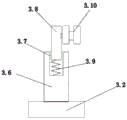
Fig. 3 is a schematic structural view of the embodiment of the present invention, wherein the lifting frame is connected with the lifting base.
Fig. 4 is a schematic structural diagram of a wiping assembly of the cable winding device for building machinery of the present invention.
Wherein the reference numerals are: 1. the base, 1.1, the guide rail, 2, receive the cable subassembly, 2.1, driving motor, 2.2, the support frame, 2.3, the rotary drum, 2.4, the action wheel, 2.5, the driven shaft, 2.6, from the driving wheel, 3, arrange the cable subassembly, 3.1, electric telescopic handle, 3.2, remove the seat, 3.3, backup pad one, 3.4, backup pad two, 3.5, the guide block, 3.6, the lift seat, 3.7, the recess, 3.8, the crane, 3.9, spring one, 3.10, the cable pressing wheel, 3.11, the guide pulley frame, 3.12, the guide pulley, 3.13, the cable through-hole, 4, clean the subassembly, 4.1, backup pad three, 4.2, the depression bar, 4.3, U template one, 4.4, U template two, 4.5, the stopper, 4.6, spring two, 4.7, the foam-rubber cushion, 5, remove the wheel, 6, the handle, 7, the antiskid cover, 8, the impurity collecting box.
Detailed Description
In order to clearly illustrate the technical features of the present solution, the present solution is explained below by way of specific embodiments.
Referring to fig. 1-4, a cable winding device for building machinery comprises a base 1, a cable take-up assembly 2 and a cable arrangement assembly 3, wherein the cable take-up assembly 2 and the cable arrangement assembly 3 are arranged on the base 1;
the cable collecting assembly 2 comprises a driving motor 2.1 arranged on the base 1, support frames 2.2 symmetrically arranged on the base 1 and a rotary drum 2.3 rotatably arranged between the two support frames 2.2, an output shaft of the driving motor 2.1 is connected with a driving wheel 2.4, one end of the rotary drum 2.3 is coaxially connected with a driven shaft 2.5, the driven shaft 2.5 penetrates through the support frames 2.2, one end of the driven shaft 2.5 penetrating out of the support frames 2.2 is connected with a driven wheel 2.6, and the driving wheel 2.4 is connected with the driven wheel 2.6 through a belt.
The cable arrangement component 3 comprises an electric telescopic rod 3.1, a moving seat 3.2, a first support plate 3.3 and a second support plate 3.4 which are symmetrically arranged on the moving seat 3.2, the electric telescopic rod 3.1 is arranged on the base 1, the output end of the electric telescopic rod 3.1 is connected with the moving seat 3.2, two ends of the bottom of the moving seat 3.2 are provided with guide blocks 3.5, the base 1 is provided with guide rails 1.1 which are respectively matched with the two guide blocks 3.5 in a sliding way, the moving seat 3.2 is provided with a lifting seat 3.6, the lifting seat 3.6 is provided with a groove 3.7, a lifting frame 3.8 is arranged in the groove 3.7 in a sliding way, the bottom of the lifting frame 3.8 is provided with a first spring 3.9, one end of the first spring 3.9, far away from the lifting frame 3.8, is connected to the bottom of the groove 3.7, one side of the lifting frame 3.8 is rotatably connected with a cable pressing wheel 3.10, guide wheels 3.12.11 are arranged on the inner sides of the first support, the guide wheel 3.12 is connected with the guide wheel 3.12 on the frame 3.11 in a rotating mode, and the first supporting plate 3.3 and the second supporting plate 3.4 are both provided with cable through holes 3.13.
A wiping component 4 is arranged on the second supporting plate 3.4, the wiping component 4 comprises a third supporting plate 4.1, a pressure rod 4.2, a first U-shaped plate 4.3 and a second U-shaped plate 4.4, the supporting plate three 4.1 is arranged on the outer side surface of the supporting plate two 3.4 and is positioned at the upper end of the cable through hole 3.13, the top of the pressure lever 4.2 is provided with a limit block 4.5, one end of the pressure lever 4.2 far away from the limit block 4.5 is arranged by penetrating through the supporting plate III 4.1, the U-shaped plate I4.3 is fixedly arranged at the bottom of the pressure lever 4.2, a spring II 4.6 is sleeved on the pressure lever 4.2, one end of the spring II 4.6 is connected to the bottom of the support plate III 4.1, one end of the second spring 4.6, which is far away from the third support plate 4.1, is connected to the first U-shaped plate 4.3, the U-shaped plate II 4.4 is arranged on the outer side surface of the support plate II 3.4 and is positioned at the lower end of the cable through hole 3.13, u type groove relative setting and U type groove department of U type plate one 4.3 with U type plate two 4.4 all are equipped with foam-rubber cushion 4.7.
The bottom of base 1 is installed and is removed wheel 5, be equipped with on the base 1 handle 6 just the cover is equipped with antiskid cover 7 on the handle 6, it has impurity collecting box 8 to have hung on the lateral surface of backup pad two 3.4, impurity collecting box 8 is located the bottom of U template two 4.4, press cable wheel 3.10 and two guide pulley 3.12 is in on same vertical plane.
When the utility model is implemented, firstly, the push handle is held by hand to move the whole device to the working place, when the cable is required to be wound, the cable passes through the cable through hole 3.13 on the support plate II 3.4 and is clamped at the U-shaped groove of the U-shaped plate II 4.4, through adjusting the height of the compression bar 4.2, the spring II 4.6 is always in a compression state and leads the U-shaped plate I4.3 and the sponge pad 4.7 of the U-shaped plate II 4.4 to be clung to the cable, then the cable passing through the cable through hole 3.13 passes through the top guide groove of the guide wheel 3.12 on the support plate II 3.4, the guide groove at the bottom of the cable pressing wheel 3.10 and the top guide groove of the guide wheel 3.12 on the support plate I3.3 in sequence, the cable passes through the cable through hole 3.13 on the support plate I3.3 and is wound on the rotary drum 2.3, at the moment, the driving motor 2.1 and the electric telescopic rod 3.1 are started, the driving motor 2.1 drives the driving wheel 2.4 to rotate, thereby realize rotating the function to the automatic roll-up of cable, need not the manpower around rolling up the cable, time saving and labor saving, simultaneously through setting up electric telescopic handle 3.1, electric telescopic handle 3.1 drives and removes seat 3.2 reciprocating motion, thereby make the cable that passes cable through-hole 3.13 can neatly be around rolling up on rotary drum 2.3, prevent the phenomenon of cable overlap, when increasing around the cable number of turns of rolling up on rotary drum 2.3, but crane 3.8 is through the effect rebound of spring two 4.6, make the cable be in tight state all the time around the in-process of rolling up, be convenient for the cable neatly arrange on rotary drum 2.3.
The technical features that the utility model has not been described can be realized through or adopt prior art, and no longer give unnecessary details here, and of course, the above-mentioned explanation is not right the utility model discloses a restriction, the utility model discloses also not only be limited to the above-mentioned example, ordinary skilled person in this technical field is in the utility model discloses a change, modification, interpolation or replacement made in the essential scope also should belong to the utility model discloses a protection scope.
Claims (4)
1. A cable winding device for building machinery is characterized by comprising a base, a cable winding assembly and a cable arrangement assembly, wherein the cable winding assembly and the cable arrangement assembly are arranged on the base;
the cable collecting assembly comprises a driving motor arranged on the base, support frames symmetrically arranged on the base and a rotary drum arranged between the two support frames in a rotating mode, an output shaft of the driving motor is connected with a driving wheel, one end of the rotary drum is coaxially connected with a driven shaft, the driven shaft penetrates through the support frames, one end of the driven shaft penetrates out of the support frames and is connected with a driven wheel, and the driving wheel is connected with the driven wheel through a belt.
2. The cable winding device for the construction machine electricity according to claim 1, wherein the cable arrangement assembly comprises an electric telescopic rod, a moving seat, a first support plate and a second support plate which are symmetrically arranged on the moving seat, the electric telescopic rod is arranged on the base, the output end of the electric telescopic rod is connected with the moving seat, two ends of the bottom of the moving seat are provided with guide blocks, the base is provided with guide rails which are respectively matched with the two guide blocks in a sliding manner, the moving seat is provided with a lifting seat, the lifting seat is provided with a groove, a lifting frame is arranged in the groove in a sliding manner, the bottom of the lifting frame is provided with a first spring, one end of the first spring, far away from the lifting frame, is connected to the bottom of the groove, one side of the lifting frame is rotatably connected with a cable pressing wheel, and guide wheel frames are arranged on the inner, the guide wheel frame is rotatably connected with a guide wheel, and the first supporting plate and the second supporting plate are both provided with cable through holes.
3. The cable winder for building machinery according to claim 2, wherein a wiping unit is provided on the second support plate, the wiping component comprises a third supporting plate, a pressure lever, a first U-shaped plate and a second U-shaped plate, the third supporting plate is arranged on the outer side surface of the second supporting plate and is positioned at the upper end of the cable through hole, the top of the pressure lever is provided with a limiting block, one end of the pressure lever far away from the limiting block penetrates through the third support plate, the first U-shaped plate is fixedly arranged at the bottom of the pressure lever, a second spring is sleeved on the pressure lever, one end of the second spring is connected to the bottom of the third support plate, one end of the second spring, which is far away from the third support plate, is connected to the first U-shaped plate, the second U-shaped plate is arranged on the outer side surface of the second support plate and is positioned at the lower end of the cable through hole, the U-shaped groove of the first U-shaped plate and the U-shaped groove of the second U-shaped plate are oppositely arranged, and sponge pads are arranged at the positions of the U-shaped grooves.
4. The cable winding device for the building machine electric cables as claimed in claim 3, wherein a moving wheel is mounted at the bottom of the base, a handle is arranged on the base and sleeved with an anti-slip sleeve, an impurity collecting box is hung on the outer side surface of the second supporting plate and positioned at the bottom of the second U-shaped plate, and the cable pressing wheel and the two guide wheels are positioned on the same vertical plane.
Priority Applications (1)
| Application Number | Priority Date | Filing Date | Title |
|---|---|---|---|
| CN202020705738.9U CN212101375U (en) | 2020-04-30 | 2020-04-30 | Cable winding device for building machine electricity |
Applications Claiming Priority (1)
| Application Number | Priority Date | Filing Date | Title |
|---|---|---|---|
| CN202020705738.9U CN212101375U (en) | 2020-04-30 | 2020-04-30 | Cable winding device for building machine electricity |
Publications (1)
| Publication Number | Publication Date |
|---|---|
| CN212101375U true CN212101375U (en) | 2020-12-08 |
Family
ID=73618972
Family Applications (1)
| Application Number | Title | Priority Date | Filing Date |
|---|---|---|---|
| CN202020705738.9U Expired - Fee Related CN212101375U (en) | 2020-04-30 | 2020-04-30 | Cable winding device for building machine electricity |
Country Status (1)
| Country | Link |
|---|---|
| CN (1) | CN212101375U (en) |
Cited By (1)
| Publication number | Priority date | Publication date | Assignee | Title |
|---|---|---|---|---|
| CN114476825A (en) * | 2022-03-17 | 2022-05-13 | 江西智盛科技有限公司 | Sewing thread production is with convenient wind who dismantles |
-
2020
- 2020-04-30 CN CN202020705738.9U patent/CN212101375U/en not_active Expired - Fee Related
Cited By (2)
| Publication number | Priority date | Publication date | Assignee | Title |
|---|---|---|---|---|
| CN114476825A (en) * | 2022-03-17 | 2022-05-13 | 江西智盛科技有限公司 | Sewing thread production is with convenient wind who dismantles |
| CN114476825B (en) * | 2022-03-17 | 2023-12-08 | 江西智盛科技有限公司 | Winding device convenient to detach for sewing thread production |
Similar Documents
| Publication | Publication Date | Title |
|---|---|---|
| CN210678237U (en) | Steel wire rope surface rust removal device | |
| CN208994867U (en) | A kind of precision wind equipment | |
| CN212101375U (en) | Cable winding device for building machine electricity | |
| CN206842664U (en) | A kind of new textile machinery roll device | |
| CN217626874U (en) | Silk thread winding equipment for textile production | |
| CN208964297U (en) | Cable taking-up device | |
| CN214455778U (en) | Cable packing and looping device | |
| CN107176483A (en) | A kind of textile machinery cloth devices for taking-up | |
| CN205042823U (en) | Sponge iron iron pipe outer wall descaling machine | |
| CN210260659U (en) | Pay-off device of winding machine | |
| CN209777972U (en) | Spinning processing wire winding auxiliary device | |
| CN112478857A (en) | Coiling mechanism is used in textile production processing | |
| CN203095278U (en) | Optical cable cutting coiling machine | |
| CN214298623U (en) | Cable coil collecting device | |
| CN212893171U (en) | Safety wire coiling machine | |
| CN211644149U (en) | Storage device convenient to control yarn rolling tension | |
| CN212800682U (en) | Waxing equipment for textile yarns | |
| CN213294213U (en) | Cutting mechanism for lint material rolling machine | |
| CN210029410U (en) | Winding device for sealing framework | |
| CN210524054U (en) | Slow-walking wire cutting machine tool with tensioning function | |
| CN210394970U (en) | Device convenient for winding steel wire rope | |
| CN207901254U (en) | The cutting facility of coil winding machine | |
| CN207511342U (en) | A kind of conveyer belt automatic cleaning equipment | |
| CN212951480U (en) | Rigging suspender packing machine | |
| CN210064747U (en) | Handling device of cable manufacture usefulness |
Legal Events
| Date | Code | Title | Description |
|---|---|---|---|
| GR01 | Patent grant | ||
| GR01 | Patent grant | ||
| CF01 | Termination of patent right due to non-payment of annual fee |
Granted publication date: 20201208 |
|
| CF01 | Termination of patent right due to non-payment of annual fee |