CN212090477U - Catheter system and connector support device - Google Patents
Catheter system and connector support device Download PDFInfo
- Publication number
- CN212090477U CN212090477U CN201922487653.8U CN201922487653U CN212090477U CN 212090477 U CN212090477 U CN 212090477U CN 201922487653 U CN201922487653 U CN 201922487653U CN 212090477 U CN212090477 U CN 212090477U
- Authority
- CN
- China
- Prior art keywords
- connector
- support device
- connector support
- catheter system
- catheter
- Prior art date
- Legal status (The legal status is an assumption and is not a legal conclusion. Google has not performed a legal analysis and makes no representation as to the accuracy of the status listed.)
- Active
Links
Images


Classifications
-
- A—HUMAN NECESSITIES
- A61—MEDICAL OR VETERINARY SCIENCE; HYGIENE
- A61M—DEVICES FOR INTRODUCING MEDIA INTO, OR ONTO, THE BODY; DEVICES FOR TRANSDUCING BODY MEDIA OR FOR TAKING MEDIA FROM THE BODY; DEVICES FOR PRODUCING OR ENDING SLEEP OR STUPOR
- A61M25/00—Catheters; Hollow probes
- A61M25/01—Introducing, guiding, advancing, emplacing or holding catheters
- A61M25/02—Holding devices, e.g. on the body
-
- A—HUMAN NECESSITIES
- A61—MEDICAL OR VETERINARY SCIENCE; HYGIENE
- A61M—DEVICES FOR INTRODUCING MEDIA INTO, OR ONTO, THE BODY; DEVICES FOR TRANSDUCING BODY MEDIA OR FOR TAKING MEDIA FROM THE BODY; DEVICES FOR PRODUCING OR ENDING SLEEP OR STUPOR
- A61M25/00—Catheters; Hollow probes
- A61M25/01—Introducing, guiding, advancing, emplacing or holding catheters
- A61M25/06—Body-piercing guide needles or the like
- A61M25/0606—"Over-the-needle" catheter assemblies, e.g. I.V. catheters
-
- A—HUMAN NECESSITIES
- A61—MEDICAL OR VETERINARY SCIENCE; HYGIENE
- A61M—DEVICES FOR INTRODUCING MEDIA INTO, OR ONTO, THE BODY; DEVICES FOR TRANSDUCING BODY MEDIA OR FOR TAKING MEDIA FROM THE BODY; DEVICES FOR PRODUCING OR ENDING SLEEP OR STUPOR
- A61M25/00—Catheters; Hollow probes
- A61M25/01—Introducing, guiding, advancing, emplacing or holding catheters
- A61M25/06—Body-piercing guide needles or the like
- A61M25/0612—Devices for protecting the needle; Devices to help insertion of the needle, e.g. wings or holders
- A61M25/0637—Butterfly or winged devices, e.g. for facilitating handling or for attachment to the skin
-
- A—HUMAN NECESSITIES
- A61—MEDICAL OR VETERINARY SCIENCE; HYGIENE
- A61M—DEVICES FOR INTRODUCING MEDIA INTO, OR ONTO, THE BODY; DEVICES FOR TRANSDUCING BODY MEDIA OR FOR TAKING MEDIA FROM THE BODY; DEVICES FOR PRODUCING OR ENDING SLEEP OR STUPOR
- A61M39/00—Tubes, tube connectors, tube couplings, valves, access sites or the like, specially adapted for medical use
- A61M39/10—Tube connectors; Tube couplings
-
- A—HUMAN NECESSITIES
- A61—MEDICAL OR VETERINARY SCIENCE; HYGIENE
- A61M—DEVICES FOR INTRODUCING MEDIA INTO, OR ONTO, THE BODY; DEVICES FOR TRANSDUCING BODY MEDIA OR FOR TAKING MEDIA FROM THE BODY; DEVICES FOR PRODUCING OR ENDING SLEEP OR STUPOR
- A61M25/00—Catheters; Hollow probes
- A61M25/01—Introducing, guiding, advancing, emplacing or holding catheters
- A61M25/02—Holding devices, e.g. on the body
- A61M2025/024—Holding devices, e.g. on the body having a clip or clamp system
-
- A—HUMAN NECESSITIES
- A61—MEDICAL OR VETERINARY SCIENCE; HYGIENE
- A61M—DEVICES FOR INTRODUCING MEDIA INTO, OR ONTO, THE BODY; DEVICES FOR TRANSDUCING BODY MEDIA OR FOR TAKING MEDIA FROM THE BODY; DEVICES FOR PRODUCING OR ENDING SLEEP OR STUPOR
- A61M25/00—Catheters; Hollow probes
- A61M25/01—Introducing, guiding, advancing, emplacing or holding catheters
- A61M25/02—Holding devices, e.g. on the body
- A61M2025/0266—Holding devices, e.g. on the body using pads, patches, tapes or the like
-
- A—HUMAN NECESSITIES
- A61—MEDICAL OR VETERINARY SCIENCE; HYGIENE
- A61M—DEVICES FOR INTRODUCING MEDIA INTO, OR ONTO, THE BODY; DEVICES FOR TRANSDUCING BODY MEDIA OR FOR TAKING MEDIA FROM THE BODY; DEVICES FOR PRODUCING OR ENDING SLEEP OR STUPOR
- A61M25/00—Catheters; Hollow probes
- A61M25/01—Introducing, guiding, advancing, emplacing or holding catheters
- A61M25/02—Holding devices, e.g. on the body
- A61M2025/028—Holding devices, e.g. on the body having a mainly rigid support structure
-
- A—HUMAN NECESSITIES
- A61—MEDICAL OR VETERINARY SCIENCE; HYGIENE
- A61M—DEVICES FOR INTRODUCING MEDIA INTO, OR ONTO, THE BODY; DEVICES FOR TRANSDUCING BODY MEDIA OR FOR TAKING MEDIA FROM THE BODY; DEVICES FOR PRODUCING OR ENDING SLEEP OR STUPOR
- A61M39/00—Tubes, tube connectors, tube couplings, valves, access sites or the like, specially adapted for medical use
- A61M39/10—Tube connectors; Tube couplings
- A61M2039/1038—Union screw connectors, e.g. hollow screw or sleeve having external threads
-
- A—HUMAN NECESSITIES
- A61—MEDICAL OR VETERINARY SCIENCE; HYGIENE
- A61M—DEVICES FOR INTRODUCING MEDIA INTO, OR ONTO, THE BODY; DEVICES FOR TRANSDUCING BODY MEDIA OR FOR TAKING MEDIA FROM THE BODY; DEVICES FOR PRODUCING OR ENDING SLEEP OR STUPOR
- A61M2209/00—Ancillary equipment
- A61M2209/08—Supports for equipment
- A61M2209/088—Supports for equipment on the body
Abstract
A catheter system includes a catheter adapter including a distal end, a proximal end, and a lumen extending through the distal end and the proximal end. The catheter system may include a connector coupled to the proximal end of the catheter adapter. The connector may comprise a T-connector. The catheter system may include a connector support device, which may be wedge-shaped to support the connector at an insertion angle. A connector support apparatus for supporting a connector coupled to a catheter assembly is also disclosed.
Description
Technical Field
The present invention relates to medical devices, and more particularly to vascular access devices, matching devices therefor, and related systems.
Background
Catheters are commonly used for a variety of infusion therapies. For example, catheters may be used to infuse fluids, such as saline solutions, various medications, and total parenteral nutrition, to a patient. Catheters may also be used to draw blood from a patient.
One common catheter is a trocar peripheral venous catheter ("PIVC"). As the name implies, a trocar PIVC may be mounted on an introducer needle having a sharp distal tip. The PIVC and the introducer needle can be assembled such that the distal tip of the introducer needle extends beyond the distal tip of the PIVC and the bevel of the needle faces upward away from the patient's skin. PIVC needles and introducer needles are typically inserted through the skin at a shallow insertion angle into the patient's vasculature.
To verify proper placement of the introducer needle and/or the PIVC in the blood vessel, the clinician typically confirms that there is a "flashback" of blood in the flashback chamber of the PIVC assembly. Once needle placement is confirmed, the clinician may temporarily occlude flow in the vasculature and remove the introducer needle, leaving the PIVC in place for future blood draws and/or fluid infusions.
Placement of PIVCs in the vasculature is essential for blood withdrawal and fluid infusion, but can be difficult to maintain. When inserting a PIVC, a patient typically desires or requires a normal range of physical movement. In addition, external objects may apply external forces to the PIVC, thereby displacing the position of the PIVC within the vasculature. In some cases, external forces may cause dynamic movement of the PIVC tip in the anterior-posterior direction, or may cause static displacement of the tip from its position within the vasculature.
The subject matter claimed herein is not limited to embodiments that solve any disadvantages or operations only in environments such as those described above. Rather, this background is provided merely to illustrate one example area of technology in which some embodiments described herein may be practiced.
SUMMERY OF THE UTILITY MODEL
The present disclosure relates generally to vascular access devices and related systems and methods. In some embodiments, a catheter system may include a catheter assembly, which may include a catheter adapter and a catheter. In some embodiments, the catheter adapter may include a distal end, a proximal end, and a lumen extending through the distal and proximal ends. In some embodiments, the catheter may extend distally from the distal end of the catheter adapter. In some embodiments, the catheter may comprise a peripheral venous catheter (PIVC) or another suitable catheter. In some embodiments, the catheter adapter may be non-integrated without an integrated extension tube extending from the side port.
In some embodiments, the catheter system may include a connector that may be coupled to the proximal end of the catheter adapter. In some embodiments, the connector may comprise a T-connector or another suitable connector. In some embodiments, the T-connector may include a body, which may include a distal end and a proximal end. In some embodiments, the T-connector may include a side port extending from the body.
In some embodiments, to place a catheter within a patient's blood vessel for fluid infusion and/or blood withdrawal, an introducer needle and catheter may be inserted into the patient's skin at an insertion angle relative to the skin. In some embodiments, the insertion angle may be about 30 ° or less. In some embodiments, the catheter system may include a connector support device, which may be wedge-shaped to support the connector at the certain insertion angle.
In some embodiments, the connector support device may facilitate stabilization of the connector and insertion of instruments through the connector and catheter. In some embodiments, the instrument may include a probe (which may include a sensor), a light pipe for sterilization, or another suitable instrument. In some embodiments, the apparatus may include another catheter and may be used to draw blood from and/or infuse fluid into a patient. In some embodiments, the instrument delivery device may be coupled to the proximal end of the connector, and the instrument may be advanced distally through the connector and into the catheter. In some embodiments, the instrument may be advanced distally beyond the catheter into a patient's blood vessel.
In some embodiments, the connector and catheter adapter may provide a linear path through which the instrument may travel and extend. More specifically, in some embodiments, the lumen of the connector may be axially aligned with the lumen of the catheter adapter. In some embodiments, the connector and connector support device may act as an extension set that is removed from the patient to an extent to prevent interference with the catheterization site. However, in some embodiments, the length of the connector and catheter adapter may not extend excessively in order to increase the reach of the instrument. In some embodiments, a blood collection or fluid infusion device may be coupled to the proximal end of the connector.
In some embodiments, the connector support means may comprise an H-shape, which may comprise four leg portions and a bridge portion. In some embodiments, the H-shape may provide stability to the connector and catheter assembly by preventing side-to-side rocking. In some embodiments, the connector support means may comprise an upper surface which may contact and support the connector. In some embodiments, the body and side port of the T-connector may be disposed on the upper surface. In some embodiments, the connector support apparatus may include a bottom surface configured to contact the skin of the patient.
In some embodiments, the connector support device may include various stabilizing features. In some embodiments, the connector support means may comprise a ring or partial ring extendable from the upper surface. In some embodiments, the connector may extend through the ring or a portion of the ring. In some embodiments, the body of the T-connector may extend through the loop or a portion of the loop. In some embodiments, the side port of the T-connector may extend through the loop or a portion of the loop.
In some embodiments, the upper surface may include a groove, which may be aligned with a longitudinal axis of the connector. In some embodiments, the connector may be disposed within the recess. In some embodiments, the upper surface may include another groove, which may be substantially perpendicular to the longitudinal axis of the connector. In some embodiments, the side port of the T-connector may be configured to be placed within another groove.
In some embodiments, the upper surface of the connector support device may include one or more protrusions that may be configured to contact a side port of a T-connector. In some embodiments, the protrusion may be disposed proximal and/or distal to the side port. In some embodiments, the protrusions may be disposed at a lateral position of the ring or portions of the ring.
In some embodiments, the connector support means may comprise a step surface forming an upper step and a lower step. In some embodiments, the upper step may include a groove. In some embodiments, the distal end of the body may include a luer adapter that may be placed within the lower step. In some embodiments, the lower step may be curved. In some embodiments, the lower step may be curved to match the cylindrical shape of the luer adapter. In some embodiments, the curved diameter of the lower step may be greater than the curved diameter of the groove. In some embodiments, the connector support device may include an extension that may extend distally from the lower step. In some embodiments, the luer adapter may be placed on the extension.
In some embodiments, the connector support device and the connector may be packaged with the connector support device pre-attached to the connector, which may prevent clinician assembly. Thus, in some embodiments, the connector support device may be connected to the connector prior to insertion of the catheter and introducer needle into the patient's blood vessel. In some embodiments, coupling of the connector support device to the connector after insertion is avoided by the clinician.
In general, in one aspect, the invention provides a catheter system comprising: a catheter adapter comprising a distal end, a proximal end, and a lumen extending through the distal and proximal ends; a connector coupled to the proximal end of the catheter adapter; and a connector support device, wherein the connector support device is wedge-shaped to support the connector at an insertion angle.
In general, in another aspect, the invention provides a connector support device for supporting a connector coupled to a catheter assembly, the connector support device comprising: an upper surface configured to contact the connector; and a bottom surface configured to contact the skin of a patient, wherein the connector support means is wedge-shaped to support the connector at an insertion angle.
It is to be understood that both the foregoing general description and the following detailed description are exemplary and explanatory only and are not restrictive of the invention, as claimed. It should be understood that the various embodiments are not limited to the arrangements and instrumentality shown in the drawings. It is also to be understood that the embodiments may be combined, or that other embodiments may be utilized, and that structural changes may be made without departing from the scope of the various embodiments of the present invention, unless so stated. The following detailed description is, therefore, not to be taken in a limiting sense.
Drawings
Exemplary embodiments of the invention will be described and explained with additional specificity and detail through the use of the accompanying drawings in which:
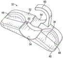
fig. 1A is an upper perspective view of an example conduit system showing an illustrative connector and connector support device, in accordance with some embodiments;
FIG. 1B is an upper perspective view of the connector support apparatus of FIG. 1A according to some embodiments;
FIG. 2A is an upper perspective view of a connector and another exemplary connector support apparatus according to some embodiments;
FIG. 2B is an upper perspective view of the connector support apparatus of FIG. 2A according to some embodiments;
FIG. 3A is an upper perspective view of a connector and another exemplary connector support apparatus according to some embodiments;
FIG. 3B is an upper perspective view of the connector support apparatus of FIG. 3A according to some embodiments;
FIG. 4A is an upper perspective view of a connector and another exemplary connector support apparatus according to some embodiments;
FIG. 4B is an upper perspective view of the connector support apparatus of FIG. 4A according to some embodiments;
FIG. 5A is an upper perspective view of a connector and another exemplary connector support apparatus according to some embodiments;
FIG. 5B is an upper perspective view of the connector support apparatus of FIG. 5A according to some embodiments;
FIG. 6A is an upper perspective view of a connector and another exemplary connector support device according to some embodiments;
FIG. 6B is an upper perspective view of the connector support apparatus of FIG. 6A according to some embodiments;
FIG. 7A is an upper perspective view of a connector and another exemplary connector support apparatus according to some embodiments, showing the connector in a first position;
FIG. 7B is an upper perspective view of the connector and connector support apparatus of FIG. 7A, showing the connector in a second position, in accordance with some embodiments;
FIG. 8A is an upper perspective view of a connector and another exemplary connector support apparatus according to some embodiments, showing the connector in a first position;
FIG. 8B is an upper perspective view of the connector and connector support apparatus of FIG. 8A, showing the connector in a second position, in accordance with some embodiments;
FIG. 9A is an upper perspective view of a connector and another exemplary connector support apparatus according to some embodiments, showing the connector in a first position;
FIG. 9B is an upper perspective view of the connector and connector support apparatus of FIG. 9A, showing the connector in a second position, in accordance with some embodiments; while
Fig. 9C is an upper perspective view of the connector support device of fig. 9A according to some embodiments.
Detailed Description
Referring now to fig. 1A-1B, in some embodiments, a catheter system 10 can include a catheter adapter 12, the catheter adapter 12 can include a distal end 14, a proximal end 18, and a lumen extending through the distal end 14 and the proximal end 18. In some embodiments, the catheter system 10 can include a catheter 20 that can extend distally from the distal end 14 of the catheter adapter 12. In some embodiments, the catheter 20 may comprise a peripheral venous catheter (PIVC) or another suitable catheter.
In some embodiments, the catheter adapter 12 may be non-integrated, without an integrated extension tube extending from the side port of the catheter adapter 12. In some embodiments, the catheter adapter 12 may be integrated, with an integrated extension tube extending from a side port of the catheter adapter 12. In some embodiments, the catheter adapter 12 may include a single-use or a multi-use blood control septum.
In some embodiments, the catheter system 10 can include a connector 22, and the connector 22 can be coupled to the proximal end 18 of the catheter adapter 12. In some embodiments, connector 22 may include a body 24, and body 24 may include a distal end 26 and a proximal end 28.
In some embodiments, distal end 26 of body 24 may include a luer adapter 29, such as a male or female luer adapter. In some embodiments, luer adapter 29 may comprise a sliding or threaded luer adapter. In some embodiments, distal end 26 of body 24 may include another luer adapter 31, such as a male or female luer adapter. In some embodiments, the other luer adapter 31 may comprise a sliding or threaded luer adapter. In some embodiments, a septum may be disposed within the connector 22.
In some embodiments, connector 22 may comprise a T-connector, such as shown in fig. 1A, or another suitable connector. In these and other embodiments, connector 22 may include a side port 30 extending from body 24. In some embodiments, side port 30 may be in fluid communication with a lumen of connector 22 extending through distal end 26 and proximal end 28. In some embodiments, extension tube 27 may extend from side port 30.
In some embodiments, to place catheter 20 within a patient's blood vessel for fluid infusion and/or blood withdrawal, an introducer needle (not shown) and catheter 20 may be inserted into the patient's skin at an insertion angle relative to the skin. In some embodiments, the insertion angle may be about 30 ° or less. In some embodiments, the insertion angle may be between 0 ° and 40 °. In some embodiments, the catheter system 10 may include a connector support device 32, and the connector support device 32 may be wedge-shaped to support the connector 22 at the certain insertion angle. More specifically, the thickness of the connector support device 32 may increase in the distal-to-proximal direction.
In some embodiments, connector support device 32 may facilitate stabilization of connector 22 and insertion of instruments (not shown) through connector 22 and catheter 20. In some embodiments, the instrument may include a probe (which may include a sensor), a light pipe for sterilization, or another suitable instrument. In some embodiments, the apparatus may include another catheter and may be used to draw blood from and/or infuse fluid into a patient. In some embodiments, the instrument delivery device may be coupled to proximal end 28 of connector 22, and the instrument may be advanced distally through connector 22 and into catheter 20. In some embodiments, the instrument may be advanced distally beyond the catheter 20 into a patient's blood vessel.
In some embodiments, the connector 22 and catheter adapter 12 may provide a straight path through which an instrument may travel and extend. More specifically, in some embodiments, the lumen of connector 22 may be axially aligned with the lumen of catheter adapter 12. In some embodiments, the connector 22 and the connector support device 32 may act as an extension set that is slightly removed from the patient's body to prevent interference with the insertion site of the catheter 20. However, in some embodiments, the length of the connector 22 and catheter adapter 12 may not be overextended, which may help increase the reach of the instrument. In some embodiments, a blood collection or fluid infusion device may be coupled to proximal end 28 of connector 22.
In some embodiments, the connector support device 32 may include an H-shape, which may include four leg portions 34 and a bridge portion 36. In some embodiments, the H-shape may provide stability to connector 22 and catheter 20 by preventing rocking in the proximal-distal direction and/or from side-to-side. In some embodiments, the H-shape may provide stability when the instrument is manipulated or inserted through connector 22.
In some embodiments, connector support device 32 may include an upper surface 38, and upper surface 38 may contact and support connector 22. In some embodiments, body 24 and side port 30 of connector 22 may be disposed on upper surface 38. In some embodiments, the connector support device 32 may include a bottom surface 40 configured to contact the patient's skin.
In some embodiments, the connector support device 32 may include various stabilizing features. In some embodiments, the connector support device 32 may include a ring 42, and the ring 42 may extend from the upper surface 38. In some embodiments, the body 24 of the connector 22 may extend through the ring 42. In some embodiments, the ring 42 may contact the connector 22 and hold the connector 22 in place snugly.
In some embodiments, the upper surface 38 may include a groove 44, and the groove 44 may be aligned with a longitudinal axis 46 of the connector 22. In some embodiments, the connector 22 may be disposed within the groove 44. In some embodiments, the thickness of the connector support 32 at the proximal end of the groove 44 may be greater than the thickness of the connector support 32 at the distal end of the groove 44, such that the groove 44 may support the connector 22 at an insertion angle.
In some embodiments, upper surface 38 of connector support device 32 may include one or more protrusions 48, and protrusions 48 may contact side ports 30. In some embodiments, projection 48 can be disposed adjacent side port 30 and can contact side port 30 in response to movement of side port 30 to stabilize side port 30. For example, as shown in fig. 1A, in some embodiments, protrusions 48 can be disposed proximal to side port 30 and/or lateral to ring 42. In some embodiments, projection 48 may be disposed distal to side port 30.
In some embodiments, the connector support device 32 may include a first protrusion on a first side of the connector support device 32 and a second protrusion on a second side of the connector support device 32 opposite the first side, e.g., as shown in fig. 1A-1B. In these and other embodiments, connector support device 32 may be compatible with side ports 30 extending from either side of connector 22. It should be understood that in some embodiments, the upper surface 38 may include a single protrusion 48. Furthermore, in some embodiments, protrusions 48 may be provided on both sides of groove 44 and/or connector support device 32 to allow support of side port 30 and connector 22 in different orientations. Further, in some embodiments, each protrusion 48 may be disposed on a single side of the groove 44 and/or the connector support device 32.
In some embodiments, the catheter system 10 may be packaged with the pre-attached connector support device 32, which may prevent clinician assembly. Thus, in some embodiments, the connector support device 32 may be coupled to the connector 22 prior to insertion of the catheter 20 and introducer needle into the patient's blood vessel. In some embodiments, coupling the connector support device 32 with the connector 22 after insertion is avoided for the clinician.
Referring now to fig. 2A-2B, in some embodiments, the connector support apparatus 32 may include a step surface 50 forming an upper step 52 and a lower step 54. In some embodiments, the upper step 52 may include a groove 44. In some embodiments, the distal end 26 of the body 24 may include a luer adapter 29, and the luer adapter 29 may be placed on and/or within the lower step 54. In some embodiments, the lower step 54 may be curved. In some embodiments, the lower step 54 may be curved to match the cylindrical shape of the luer adapter 29. In some embodiments, the curved diameter of the lower step 54 may be greater than the curved diameter of the groove 44, which may reduce resistance of the luer adapter 29 during assembly of the catheter system 10. In some embodiments, the luer adapter 29 may be disposed between the first protrusion 48b and the second protrusion 48 b.
Referring now to fig. 4A-4B, in some embodiments, side port 30 may be disposed between a set of projections 48, for example, as shown in fig. 4A. In some embodiments, the upper surface 38 of the connector support device 32 may include four of the projections 48.
Referring now to fig. 5A-5B, in some embodiments, ring 42 can be oriented to receive side port 30 of connector 22, and side port 30 can extend through ring 42. In these embodiments, the ring 42 may be oriented substantially perpendicular to the longitudinal axis 46 of the connector 22 and/or the groove 44. In some embodiments, ring 42 may contact side port 30 and hold side port 30 in place snugly. In some embodiments, placing the ring 42 as shown in fig. 5A-5B may couple the connector 22 to the catheter adapter 12 before the connector support device 32 is coupled to the connector 22.
Referring now to fig. 6A-6B, in some embodiments, the connector support device 32 can include an extension 56 that can extend distally from the lower step 54. In some embodiments, luer adapter 29 may be placed on extension 56. In some embodiments, the extension 56 may improve patient comfort.
In some embodiments, at least a portion of the connector support device 32 may be constructed of a rigid material. In some embodiments, at least a portion of the connector support device 32, such as the extension 56, may be constructed of a soft, flexible material that can conform to the patient's skin.
Referring now to fig. 7A-7B, in some embodiments, a protrusion 48 may be disposed distal to side port 30. In some embodiments, side port 30 may be disposed between ring 42 and a particular protrusion 48.
Referring now to fig. 8A-8B, in some embodiments, the upper surface 38 may include one or more other grooves 58, and these grooves 58 may be generally perpendicular to the longitudinal axis 46 of the connector 22. In some embodiments, side port 30 of connector 22 may be configured to be placed within other groove 58.
Referring now to fig. 9A-9B, in some embodiments, the connector support device 32 may include a partial ring 60, which may extend from the upper surface 38. In some embodiments, the ring 42 described with respect to one or more of the preceding figures may be replaced with a partial ring 60. In some embodiments, the body 24 of the connector 22 may extend through a portion of the ring 60. In some embodiments, a portion of the ring 60 may contact the connector 22 and hold the connector 22 in place snugly.
In some embodiments, the connector support device 32 may be pre-attached to the connector 22 prior to shipment and/or prior to insertion of the catheter system 10 into the vasculature of a patient. In some embodiments, partial ring 60 may facilitate removal of connector support device 32, and connector support device 32 may be reused.
In some embodiments, the connector support device 32 may be coupled to the proximal end 18 of the catheter adapter 12. In some embodiments, the connector support device 32 may be integrally formed with the proximal end 18 of the catheter adapter 12 as a single unit.
In some embodiments, the bottom surface 40 of the connector support device 32 may include an adhesive, which may facilitate attachment to the patient's skin. In some embodiments, an adhesive may be disposed between the connector 22 and the connector support device 32. In these and other embodiments, the connector 22 may be secured to the connector support device 32 via magnets, straps, or any other suitable coupling mechanism.
In some embodiments, another extension tube may be disposed between connector 22 and catheter adapter 12. In some embodiments, the further extension tube may be stiffer than the extension tube 27 to facilitate the axial path of insertion of an instrument through the further extension tube. In some embodiments, a needleless connector may be disposed between connector 22 and catheter adapter 12. In some embodiments, the needleless connector may be integrally formed with the catheter adapter 12 as a single unit, or may be removable from the catheter adapter 12.
In some embodiments, the catheter system 10 may include any suitable needle safety mechanism, including, for example, a passive or active needle safety mechanism. In some embodiments, the catheter system 10 may not include a needle safety mechanism. In some embodiments, the introducer needle and/or needle safety mechanism may be removed prior to coupling connector 22 to catheter adapter 12.
All examples and conditional language recited herein are intended for pedagogical purposes to aid the reader in understanding the invention and the concepts contributed by the inventor to furthering the art, and are to be construed as being without limitation to such specifically recited examples and conditions. Although the embodiments of the present invention have been described in detail, it should be understood that the various changes, substitutions, and alterations could be made hereto without departing from the spirit and scope of the invention.
Claims (20)
1. A catheter system, comprising:
a catheter adapter comprising a distal end, a proximal end, and a lumen extending through the distal and proximal ends;
a connector coupled to the proximal end of the catheter adapter; and
a connector support device, wherein the connector support device is wedge-shaped to support the connector at an insertion angle.
2. The catheter system of claim 1, wherein the connector support device is H-shaped having four leg portions and a bridge portion.
3. The catheter system of claim 1, wherein the connector support device comprises:
an upper surface contacting the connector;
a bottom surface configured to contact a patient's skin;
a ring or partial ring extending from the upper surface, wherein the connector extends through the ring or partial ring.
4. The catheter system of claim 3, wherein the upper surface includes a groove aligned with a longitudinal axis of the connector, wherein the connector is disposed within the groove.
5. The catheter system of claim 1, wherein the connector comprises a T-connector, wherein the T-connector comprises a body and a side port extending from the body, wherein the body comprises a distal end and a proximal end.
6. The catheter system of claim 5, wherein the connector support device comprises:
an upper surface contacting the connector; and
a bottom surface configured to contact a patient's skin,
wherein the upper surface includes a groove that is substantially perpendicular to a longitudinal axis of the connector, wherein the side port is configured to be disposed within the groove.
7. The catheter system of claim 5, wherein the body and the side port are disposed on an upper surface of the connector support device.
8. The catheter system of claim 7, wherein the connector support device further comprises a ring or partial ring extending from the upper surface, wherein the side port extends through the ring or partial ring.
9. The catheter system of claim 7, wherein the connector support device includes a protrusion disposed proximal to the side port and configured to contact the side port.
10. The catheter system of claim 7, wherein the connector support device includes a protrusion disposed distal to the side port and configured to contact the side port.
11. The catheter system of claim 7, wherein the connector support device comprises a step surface forming an upper step and a lower step, wherein the distal end of the connector comprises a luer adapter disposed within the lower step.
12. The catheter system of claim 11, wherein the connector support device comprises a plurality of protrusions configured to contact the side port, wherein the luer adapter is disposed between the plurality of protrusions.
13. The catheter system of claim 11, wherein the lower step is curved to match a cylindrical shape of the luer adapter.
14. The catheter system of claim 13, wherein the connector support device comprises an extension extending distally from the lower step, wherein the luer adapter is disposed on the extension.
15. A connector support device for supporting a connector coupled to a catheter assembly, the connector support device comprising:
an upper surface configured to contact the connector; and
a bottom surface configured to contact the skin of a patient, wherein the connector support device is wedge-shaped to support the connector at an insertion angle.
16. The connector support device of claim 15, wherein the connector support device is H-shaped having four leg portions and a bridge portion.
17. The connector support device of claim 15, further comprising a ring or partial ring extending from the upper surface, wherein the ring is configured to receive the connector.
18. The connector support device of claim 15, wherein the upper surface includes a groove configured to align with a longitudinal axis of the connector and receive the connector.
19. The connector support device of claim 18, wherein the upper surface comprises another groove disposed substantially perpendicular to the groove, wherein the other groove is configured to receive a side port of the connector.
20. The connector support device of claim 19, wherein the upper surface includes a protrusion configured to contact the side port.
Applications Claiming Priority (2)
| Application Number | Priority Date | Filing Date | Title |
|---|---|---|---|
| US201862786732P | 2018-12-31 | 2018-12-31 | |
| US62/786,732 | 2018-12-31 |
Publications (1)
| Publication Number | Publication Date |
|---|---|
| CN212090477U true CN212090477U (en) | 2020-12-08 |
Family
ID=71122419
Family Applications (1)
| Application Number | Title | Priority Date | Filing Date |
|---|---|---|---|
| CN201922487653.8U Active CN212090477U (en) | 2018-12-31 | 2019-12-31 | Catheter system and connector support device |
Country Status (11)
| Country | Link |
|---|---|
| US (2) | US11497891B2 (en) |
| EP (1) | EP3906084A1 (en) |
| JP (1) | JP2022516628A (en) |
| KR (1) | KR20210110628A (en) |
| CN (1) | CN212090477U (en) |
| AU (1) | AU2019419358A1 (en) |
| BR (1) | BR112021012298A2 (en) |
| CA (1) | CA3124318A1 (en) |
| MX (1) | MX2021006958A (en) |
| SG (1) | SG11202106119YA (en) |
| WO (1) | WO2020142205A1 (en) |
Families Citing this family (1)
| Publication number | Priority date | Publication date | Assignee | Title |
|---|---|---|---|---|
| WO2023163378A1 (en) * | 2022-02-23 | 2023-08-31 | 김용현 | Air-filled medical liquid pumping apparatus, medical liquid injection apparatus, and method for manufacturing air-filled medical liquid pumping apparatus |
Family Cites Families (8)
| Publication number | Priority date | Publication date | Assignee | Title |
|---|---|---|---|---|
| US6231547B1 (en) * | 1999-02-18 | 2001-05-15 | Abbott Laboratories | External retaining device for a catheter and catheter assembly and method using same |
| US8585655B2 (en) | 2005-05-23 | 2013-11-19 | Venetec International, Inc. | Securement device for I.V. t-connector |
| WO2008151047A1 (en) | 2007-06-01 | 2008-12-11 | Medical Device Group, Inc. | Universal catheter securement device |
| US8827960B2 (en) | 2008-04-14 | 2014-09-09 | A & R Possibilities, LLP | Catheter anchoring system, apparatus and method |
| JP2013507186A (en) * | 2009-10-06 | 2013-03-04 | ヴェネテック・インターナショナル,インコーポレーテッド | Stabilization device with snap clamp |
| JP5837094B2 (en) | 2011-01-31 | 2015-12-24 | イー ヘルム ジュニア ロバート | Snap-sealed sterile intravascular catheter dressing system |
| EP3347083A1 (en) * | 2015-09-09 | 2018-07-18 | B. Braun Melsungen AG | Infusion systems, connectors for use with catheter devices, and related methods |
| AU2018277084B2 (en) * | 2017-05-30 | 2023-06-15 | Velano Vascular, Inc. | Stabilization devices for vascular access and methods of using the same |
-
2019
- 2019-12-16 US US16/716,142 patent/US11497891B2/en active Active
- 2019-12-17 CA CA3124318A patent/CA3124318A1/en active Pending
- 2019-12-17 WO PCT/US2019/066885 patent/WO2020142205A1/en unknown
- 2019-12-17 JP JP2021538691A patent/JP2022516628A/en active Pending
- 2019-12-17 KR KR1020217023319A patent/KR20210110628A/en unknown
- 2019-12-17 BR BR112021012298-2A patent/BR112021012298A2/en unknown
- 2019-12-17 EP EP19836903.5A patent/EP3906084A1/en active Pending
- 2019-12-17 MX MX2021006958A patent/MX2021006958A/en unknown
- 2019-12-17 AU AU2019419358A patent/AU2019419358A1/en active Pending
- 2019-12-17 SG SG11202106119YA patent/SG11202106119YA/en unknown
- 2019-12-31 CN CN201922487653.8U patent/CN212090477U/en active Active
-
2022
- 2022-09-29 US US17/956,580 patent/US20230012763A1/en active Pending
Also Published As
| Publication number | Publication date |
|---|---|
| BR112021012298A2 (en) | 2021-09-08 |
| JP2022516628A (en) | 2022-03-01 |
| MX2021006958A (en) | 2021-07-15 |
| US20200206467A1 (en) | 2020-07-02 |
| SG11202106119YA (en) | 2021-07-29 |
| CA3124318A1 (en) | 2020-07-09 |
| AU2019419358A1 (en) | 2021-07-22 |
| KR20210110628A (en) | 2021-09-08 |
| US11497891B2 (en) | 2022-11-15 |
| EP3906084A1 (en) | 2021-11-10 |
| WO2020142205A1 (en) | 2020-07-09 |
| US20230012763A1 (en) | 2023-01-19 |
Similar Documents
| Publication | Publication Date | Title |
|---|---|---|
| CN112154005B (en) | Catheter system with remote instrument delivery | |
| CN112672779B (en) | Peripheral intravenous catheter assembly with extension kit | |
| US11717650B2 (en) | Catheter stabilization platform, systems, and methods | |
| CN217067263U (en) | Vascular access instrument propulsion device | |
| CA3109517A1 (en) | Systems of facilitating instrument delivery to a catheter assembly | |
| CN212090477U (en) | Catheter system and connector support device | |
| US11865274B2 (en) | Catheter system for pediatric treatment | |
| JP2023520011A (en) | Pediatric catheter system and related devices and methods | |
| US20240066273A1 (en) | Extension Set Having Distally-Directed Extension Tube | |
| US20210379339A1 (en) | Needle cover retention | |
| CN218458113U (en) | Catheter system | |
| CN219501806U (en) | Vascular access system | |
| US20240066266A1 (en) | Non-Integrated Vascular Access System with Stabilization | |
| CN219307689U (en) | Integrated intravenous catheter | |
| US20230166086A1 (en) | Integrated Catheter with Stabilized Near-Patient Port Extension Set Architecture | |
| US20240066265A1 (en) | Catheter Assembly with Elongated Arm and Stabilization Platform | |
| WO2024049745A1 (en) | Catheter assembly with distally-directed tube |
Legal Events
| Date | Code | Title | Description |
|---|---|---|---|
| GR01 | Patent grant | ||
| GR01 | Patent grant |