CN212089863U - Foot drop correcting mechanism - Google Patents
Foot drop correcting mechanism Download PDFInfo
- Publication number
- CN212089863U CN212089863U CN202020355250.8U CN202020355250U CN212089863U CN 212089863 U CN212089863 U CN 212089863U CN 202020355250 U CN202020355250 U CN 202020355250U CN 212089863 U CN212089863 U CN 212089863U
- Authority
- CN
- China
- Prior art keywords
- foot
- hole
- leg support
- plate
- bottom plate
- Prior art date
- Legal status (The legal status is an assumption and is not a legal conclusion. Google has not performed a legal analysis and makes no representation as to the accuracy of the status listed.)
- Active
Links
Images


Abstract
The utility model discloses a foot drop correcting mechanism, which comprises a foot bottom plate and leg supports, wherein the foot bottom plate is matched with the contour of the heel of a human body, arc-shaped foot support sides are arranged on two sides of the foot bottom plate, and the foot support sides are provided with adhesive buckle belts for connecting the two foot support sides; the rear side of the sole plate is provided with a leg support connecting portion, the leg support connecting portion is provided with a connecting hole, a rotating shaft is arranged in the connecting hole, the middle of the rotating shaft is provided with a ball head sleeve, the ball head sleeve is communicated with a positioning threaded hole, and the positioning threaded hole is in threaded connection with a positioning screw rod. The utility model has simple structure, practicality and convenience; can make the patient all can keep ankle joint functional position state under any state, can make patient's foot and low limbs be 90 degrees, also can incline certain angle to the place ahead, respectively incline certain angle to the right side left, change and all can block to every angle, play the fixed action.
Description
Technical Field
The utility model belongs to the technical field of medical instrument, concretely relates to drop foot orthotic devices.
Background
Foot drop is a main cause causing gait abnormity, the daily life capacity of a patient is seriously reduced, rehabilitation therapy is an effective method for reducing disability rate, and a foot drop corrector is frequently adopted at present, but has a plurality of problems: the market-sold multi-position universal type is not suitable for many people, and secondary damage can be caused by forced use; the structure adopted is either too simple to meet the requirements of patients or too complex and high in cost and is not practical.
Disclosure of Invention
In order to overcome the defects of the prior art, the utility model discloses a foot drop correction mechanism which has simple structure, is practical and convenient and can play a preventive role in foot drop.
In order to achieve the above purpose, the utility model adopts the technical scheme that:
the foot drop correction mechanism comprises a foot bottom plate and a leg support,
the sole plate is matched with the contour of the heel of a human body, arc-shaped foot supporting uppers are arranged on two sides of the sole plate, and the foot supporting uppers are provided with adhesive fastening belts for connecting the two foot supporting uppers; the rear side of the foot bottom plate is provided with a leg support connecting part, the leg support connecting part is provided with a connecting hole, a rotating shaft is arranged in the connecting hole, the middle part of the rotating shaft is provided with a ball head sleeve, the ball head sleeve is communicated with a positioning threaded hole, and a positioning screw rod is connected with the positioning threaded hole in a threaded manner;
the leg support is matched with the contour of the position of the human shank, the lower end of the leg support is provided with a connecting rod, the lower end of the connecting rod is provided with a hemisphere, and the hemisphere is sleeved in the ball head sleeve; the leg support is provided with adhesive buckle belts connected with the two sides of the leg support; the hemisphere can be fixed by screwing the positioning screw rod, so that the hemisphere is prevented from rotating randomly.
Preferably, the adjustable width of sole board, it includes first sole board, second sole board, two at least synchronizing shafts and an adjusting bolt, first sole board with the shaft hole has been seted up to the relative one side correspondence of second sole board, the synchronizing shaft install in the shaft hole, first screw hole has been seted up to the middle part inboard of first sole board, the through-hole with first screw hole coaxial line is seted up to the second sole, adjusting bolt passes the through-hole with first screw hole is connected, can realize the distance adjustment between first sole board and the second sole board through rotating adjusting bolt.
Preferably, the middle part of the sole plate is provided with a plurality of vent holes, so that ventilation is facilitated; the inner sides of the foot bottom plate and the leg support are respectively provided with a breathable pressure sore prevention soft material layer.
Preferably, the sum of the length of the first threaded hole and the length of the through hole is equal to the length of a screw rod of the adjusting bolt; the sum of the lengths of the shaft hole of the first foot bottom plate and the shaft hole of the second foot bottom plate is equal to the length of the synchronizing shaft.
Preferably, the head of the adjusting bolt is in a cross structure.
Compared with the prior art, the beneficial effects of the utility model reside in that:
1. the utility model has simple structure, practicality and convenience;
2. the utility model discloses can make the patient homoenergetic keep ankle joint functional position state under any state, can make patient's foot and low limbs be 90 degrees, also can incline certain angle to the place ahead, respectively incline certain angle to the right left, change every angle and all can block, play the fixed action.
Drawings
The accompanying drawings, which are incorporated in and constitute a part of this application, are included to provide a further understanding of the invention, and are incorporated in and constitute a part of this specification. In the drawings:
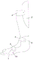
FIG. 1 is a view showing a usage state of the present invention;
FIG. 2 is a schematic structural view of the present invention;
FIG. 3 is a top view of the sole plate of the present invention;
FIG. 4 is a schematic structural view of the leg rest of the present invention;
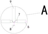
fig. 5 is an enlarged view of a in fig. 4.
Detailed Description
It should be noted that the embodiments and features of the embodiments in the present application may be combined with each other without conflict. The present invention will be described in detail below with reference to the accompanying drawings in conjunction with embodiments.
In order to make the technical solutions better understood by those skilled in the art, the technical solutions in the embodiments of the present application will be clearly and completely described below with reference to the drawings in the embodiments of the present application, and it is obvious that the described embodiments are only partial embodiments of the present application, but not all embodiments. All other embodiments, which can be derived by a person skilled in the art from the embodiments given herein without making any creative effort, shall fall within the protection scope of the present application.
As shown in fig. 1 to 4, the foot drop correction mechanism comprises a foot bottom plate 1 and a leg support 2,
the sole plate 1 is matched with the contour of a heel of a human body, arc-shaped foot supporting uppers 3 are arranged on two sides of the sole plate 1, and the foot supporting uppers 3 are provided with adhesive fastening tapes 4 for connecting the two foot supporting uppers 3; a leg support connecting part 5 is arranged on the rear side of the sole plate 1, the leg support connecting part 5 is provided with a connecting hole 6, a rotating shaft 7 is arranged in the connecting hole 6, a ball head sleeve is arranged in the middle of the rotating shaft 7 and communicated with a positioning threaded hole, and a positioning screw rod 8 is connected with the positioning threaded hole in a threaded manner;
the leg support 2 is matched with the contour of the position of the human shank, the lower end of the leg support is provided with a connecting rod 9, the lower end of the connecting rod 9 is provided with a hemisphere, and the hemisphere is sleeved in the ball head sleeve; the leg support 2 is provided with adhesive buckle belts 4 connected with the two sides of the leg support; the hemisphere can be fixed by screwing the positioning screw 8, so that the hemisphere is prevented from rotating randomly.
The adjustable width of sole board 1, it includes first sole board 10, second sole board 11, two at least synchronizing shaft 12 and an adjusting bolt 13, first sole board 10 with the corresponding shaft hole of having seted up in the relative one side of second sole board 11, synchronizing shaft 12 install in the shaft hole, first screw hole has been seted up to the middle part inboard of first sole board 10, the through-hole with first screw hole coaxial line is seted up to the second sole, adjusting bolt 13 passes the through-hole with first screw hole is connected, can realize the distance adjustment between first sole board 10 and the second sole board 11 through rotating adjusting bolt 13. It can be adjusted according to the width of the foot of the patient and is suitable for feet with various sizes.
The middle part of the sole plate 1 is provided with a plurality of vent holes 14, so that ventilation is facilitated; the inner sides of the foot bottom plate 1 and the leg support 2 are respectively provided with a breathable pressure sore prevention soft material layer.
The sum of the length of the first threaded hole and the length of the through hole is equal to the screw length of the adjusting bolt 13; the sum of the lengths of the shaft hole of the first sole plate 10 and the shaft hole of the second sole plate 11 is equal to the length of the synchronizing shaft 12.
The head of the adjusting bolt 13 is in a cross structure.
Position of the adhesive tape 4: the patient can be fixed on the back of the foot, the ankle and the upper part of the ankle sufficiently.
The sole plate 1 and the leg support 2 are both made of hard plastics.
The above description is only a preferred embodiment of the present invention and is not intended to limit the present invention, and various modifications and changes may be made by those skilled in the art. Any modification, equivalent replacement, improvement, component separation or combination made within the spirit and principle of the present invention should be included in the protection scope of the present invention.
Claims (5)
1. The foot drop correction mechanism is characterized by comprising a foot bottom plate and a leg support,
the sole plate is matched with the contour of the heel of a human body, arc-shaped foot supporting uppers are arranged on two sides of the sole plate, and the foot supporting uppers are provided with adhesive fastening belts for connecting the two foot supporting uppers; the rear side of the foot bottom plate is provided with a leg support connecting part, the leg support connecting part is provided with a connecting hole, a rotating shaft is arranged in the connecting hole, the middle part of the rotating shaft is provided with a ball head sleeve, the ball head sleeve is communicated with a positioning threaded hole, and a positioning screw rod is connected with the positioning threaded hole in a threaded manner;
the leg support is matched with the contour of the position of the human shank, the lower end of the leg support is provided with a connecting rod, the lower end of the connecting rod is provided with a hemisphere, and the hemisphere is sleeved in the ball head sleeve; the leg support is provided with adhesive buckle belts connected with the two sides of the leg support; the hemisphere can be fixed by screwing the positioning screw rod, so that the hemisphere is prevented from rotating randomly.
2. The mechanism of claim 1, wherein the foot plate has an adjustable width, and comprises a first foot plate, a second foot plate, at least two synchronizing shafts and an adjusting bolt, wherein the first foot plate and the second foot plate have corresponding shaft holes on opposite sides, the synchronizing shafts are mounted in the shaft holes, the first threaded hole is formed on the inner side of the middle portion of the first foot plate, the second foot plate has a through hole coaxial with the first threaded hole, the adjusting bolt passes through the through hole and is connected with the first threaded hole, and the adjusting bolt can be rotated to adjust the distance between the first foot plate and the second foot plate.
3. The mechanism of claim 1, wherein the sole plate has a plurality of ventilation holes at the middle portion thereof for ventilation; the inner sides of the foot bottom plate and the leg support are respectively provided with a breathable pressure sore prevention soft material layer.
4. The mechanism of claim 2, wherein the sum of the length of the first threaded hole and the length of the through hole is equal to the length of the screw of the adjustment bolt; the sum of the lengths of the shaft hole of the first foot bottom plate and the shaft hole of the second foot bottom plate is equal to the length of the synchronizing shaft.
5. The mechanism of claim 2, wherein the head of the adjustment bolt is of a cross configuration.
Priority Applications (1)
| Application Number | Priority Date | Filing Date | Title |
|---|---|---|---|
| CN202020355250.8U CN212089863U (en) | 2020-03-19 | 2020-03-19 | Foot drop correcting mechanism |
Applications Claiming Priority (1)
| Application Number | Priority Date | Filing Date | Title |
|---|---|---|---|
| CN202020355250.8U CN212089863U (en) | 2020-03-19 | 2020-03-19 | Foot drop correcting mechanism |
Publications (1)
| Publication Number | Publication Date |
|---|---|
| CN212089863U true CN212089863U (en) | 2020-12-08 |
Family
ID=73638540
Family Applications (1)
| Application Number | Title | Priority Date | Filing Date |
|---|---|---|---|
| CN202020355250.8U Active CN212089863U (en) | 2020-03-19 | 2020-03-19 | Foot drop correcting mechanism |
Country Status (1)
| Country | Link |
|---|---|
| CN (1) | CN212089863U (en) |
Cited By (1)
| Publication number | Priority date | Publication date | Assignee | Title |
|---|---|---|---|---|
| CN113230089A (en) * | 2021-05-20 | 2021-08-10 | 山西白求恩医院(山西医学科学院) | Medical device for assisting rotation of forearm and flexion and extension of elbow joint |
-
2020
- 2020-03-19 CN CN202020355250.8U patent/CN212089863U/en active Active
Cited By (1)
| Publication number | Priority date | Publication date | Assignee | Title |
|---|---|---|---|---|
| CN113230089A (en) * | 2021-05-20 | 2021-08-10 | 山西白求恩医院(山西医学科学院) | Medical device for assisting rotation of forearm and flexion and extension of elbow joint |
Similar Documents
| Publication | Publication Date | Title |
|---|---|---|
| CN203915158U (en) | Unilateral orthopaedic device for knee | |
| CN212089863U (en) | Foot drop correcting mechanism | |
| CN210301344U (en) | Medical orthopedics patient postoperative rehabilitation tempers nursing device | |
| CN201085713Y (en) | Cerebral pasly correction shoes | |
| CN202086627U (en) | Instrument for preventing malformation of foot and ankle joints | |
| CN2683068Y (en) | Adjustable orthotic device for ankle and foot | |
| CN211535028U (en) | Wearable intelligent human posture corrector | |
| CN212730890U (en) | Clinical portable knee joint trainer of using | |
| CN204542490U (en) | A kind of adjustable T-shaped shoes | |
| CN100522115C (en) | Shoe for correcting cerebral paralysis | |
| CN108294853B (en) | Movable orthopedic traction frame | |
| CN111839856A (en) | Leg-shaped foot type internal and external rotation corrector | |
| CN219439621U (en) | Ankle joint rehabilitation brace | |
| CN217853696U (en) | Multi-functional pillow of sore is pressed to prevention heel | |
| CN205569146U (en) | Orthopedic ware of eight characters in children with adjustable | |
| CN218923697U (en) | Special buckling exercise device after knee joint replacement operation | |
| CN215192709U (en) | But angle of adjustment's orthopedics prevents hanging shoes | |
| CN219762542U (en) | Lumbar adjustable perineum operation postoperative pressurization trousers | |
| CN213666350U (en) | Functional position shank support | |
| CN211485129U (en) | Correction device for adjuvant therapy of gonitis | |
| CN219878524U (en) | Adjustable T-shaped shoes for preventing pressure sores | |
| CN210612300U (en) | Height-adjustable foot varus deformity corrector | |
| CN209827153U (en) | Shoes for preventing dislocation after hip joint operation | |
| CN216676060U (en) | Posture correction fixer for lower limbs | |
| CN219148095U (en) | Orthopedic back frame for spinal correction |
Legal Events
| Date | Code | Title | Description |
|---|---|---|---|
| GR01 | Patent grant | ||
| GR01 | Patent grant |