CN212085370U - Table hole mobile socket - Google Patents
Table hole mobile socket Download PDFInfo
- Publication number
- CN212085370U CN212085370U CN202021177258.6U CN202021177258U CN212085370U CN 212085370 U CN212085370 U CN 212085370U CN 202021177258 U CN202021177258 U CN 202021177258U CN 212085370 U CN212085370 U CN 212085370U
- Authority
- CN
- China
- Prior art keywords
- socket
- wireless charging
- ontology
- wireless
- interface
- Prior art date
- Legal status (The legal status is an assumption and is not a legal conclusion. Google has not performed a legal analysis and makes no representation as to the accuracy of the status listed.)
- Active
Links
Images


Abstract
The utility model discloses a table hole mobile socket. The table hole movable socket is inserted into the threading hole when not in use by using the existing threading hole on a common office table; when the socket is used, the socket can be taken out to be used on the threading hole, the threading hole can also be taken out to be placed on a table top for use, and the wireless charging cover or the wireless charging equipment arranged on the socket body can be moved to other places for use; the wireless charging cover can be used after rotating on the socket body for a set angle; in addition, still contain other functions on the socket ontology top panel, charge mouthful like USB, RJ interface and HDMI interface etc. have increased this socket ontology's service function, when the USB that does not use the socket ontology top charges mouthful, RJ interface, wireless connector and the HDMI interface of charging, can cover the top of socket ontology with wireless lid that charges, avoid the entering of dust, this table hole mobile socket overall structure is compact, novel and the function is many, consequently, has fine practicality.
Description
Technical Field
The utility model relates to a socket technical field, more specifically say, in particular to table hole mobile socket.
Background
The socket is also called a power socket, and is a socket into which one or more circuit wiring can be inserted, and various wiring can be inserted through the socket, so that the socket can be conveniently communicated with other circuits. The power socket is an electrical device for providing a power interface for household appliances, is also an electrical accessory used in the electrical design of a house, and has a very close relationship with the life of people. After the residents move into new residences, the fact that the number of power sockets is too small is generally reflected, the use is extremely inconvenient, the residents are caused to pull and disorderly connect power lines and additionally install socket wiring boards, personal electric shock and electric fire accidents are often caused, and great hidden dangers are brought to personal and property safety. Therefore, the design of the power outlet is also an important basis for evaluating the electrical design of a house. The outlet may be classified into an industrial outlet, a power outlet, a mobile outlet, and the like according to the purpose.
Some sockets for table tops in the market are punched on the table tops and then fixed on the table tops for use; some table tops are used after being punched with holes and then inserted into the table holes; there is not a socket which can be used on a threading hole, can be taken out to be used on a table top and can move partial functions to be used elsewhere.
To this end, we propose a desk hole moving socket to solve the above problems.
SUMMERY OF THE UTILITY MODEL
The utility model aims at solving the problems in the prior art and providing a table hole mobile socket.
In order to achieve the above purpose, the utility model adopts the following technical scheme:
the utility model provides a table hole removes socket, includes the table and sets up the socket ontology on the table, be provided with the table hole that corresponds with socket ontology on the table, socket ontology's bottom is connected with the plug through the wire, be provided with forceful electric power socket on socket ontology's the side board, be provided with USB on socket ontology's the top panel and charge mouth, RJ interface, HDMI interface and wireless connector that charges.
Preferably, the detachable wireless charging cover is installed at the top of the socket body, and the wireless charging cover is electrically connected with the wireless charging connector.
Preferably, the wireless charging cover is electrically connected with the wireless charging connector through a connecting wire.
Preferably, the wireless charging connector is electrically connected with a wireless charging device, and the bottom of the wireless charging device is in contact with the top of the socket body.
Preferably, the wireless charging device is connected with the wireless charging connection port through a connection wire.
Preferably, the wireless charging connecting port is used for supplying power to the wireless charging cover and the wireless charging equipment.
The embodiment of the utility model provides a technical scheme can include following beneficial effect:
in the utility model, the table hole mobile socket borrows the existing threading hole on the common office table, and is inserted into the threading hole when not in use; when the socket is used, the socket can be taken out to be used on the threading hole, the threading hole can also be taken out to be placed on a table top for use, and the wireless charging cover or the wireless charging equipment arranged on the socket body can be moved to other places for use; the wireless charging cover can be used after rotating on the socket body for a set angle; in addition, still contain other functions on the socket ontology top panel, charge mouthful like USB, RJ interface and HDMI interface etc. have increased this socket ontology's service function, when the USB that does not use the socket ontology top charges mouthful, RJ interface, wireless connector and the HDMI interface of charging, can cover the top of socket ontology with wireless lid that charges, avoid the entering of dust, this table hole mobile socket overall structure is compact, novel and the function is many, consequently, has fine practicality.
Drawings
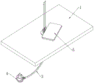
Fig. 1 is a schematic view of a use structure of an insert seat body in a table hole of a table hole mobile socket provided by the present invention, the insert seat body is located in the table hole on a table plate;
fig. 2 is a schematic structural view of the plug seat body in the table hole mobile socket according to the present invention when the plug seat body is pulled out from the table plate and the wireless charging cover rotates a certain angle;
fig. 3 is a schematic structural view of the wireless charging cover in the table hole mobile socket according to the present invention when rotating a certain angle;
fig. 4 is a schematic structural view of the wireless charging device installed on the socket body in the table hole mobile socket provided by the present invention;
fig. 5 is a schematic structural view of the wireless charging device in the table hole mobile socket according to the present invention rotating a certain angle;
fig. 6 is a schematic structural view of the table hole mobile socket body provided by the present invention when the socket body is pulled out from the table plate and the wireless charging device is rotated by a certain angle;
fig. 7 is a schematic structural view of the socket body in the table hole mobile socket according to the present invention when being pulled out from the table plate;
fig. 8 is a schematic structural view of the socket body in the table hole mobile socket according to the present invention, when the socket body is obliquely placed on the table top and in the wireless charging and USB power-off states;
fig. 9 is a schematic structural diagram of the table hole mobile socket in a vertical charging state when the wireless charging device is moved out;
fig. 10 is a schematic structural view of the wireless charging cover in the table hole mobile socket when the wireless charging cover is moved out of the state.
In the figure: 1. a table plate; 2. a wireless charging cover; 3. a wire; 4. a plug; 5. a wireless charging device; 6. a socket body; 7. a USB charging port; 8. a strong electric socket.
Detailed Description
The technical solutions in the embodiments of the present invention will be described clearly and completely with reference to the accompanying drawings in the embodiments of the present invention, and it is obvious that the described embodiments are only some embodiments of the present invention, not all embodiments.
Example one
Referring to fig. 1, a table hole mobile socket, including table 1 and socket ontology 6 of setting on table 1, be provided with the table hole that corresponds with socket ontology 6 on the table 1, socket ontology 6's bottom is connected with plug 4 through wire 3, is provided with forceful electric power socket 8 on socket ontology 6's the side board, is provided with USB on socket ontology 6's the top panel and charges mouthful 7, RJ interface, HDMI interface and the wireless connector that charges.
Further, detachable wireless charging cover 2 is installed at the top of socket body 6, and wireless charging cover 2 and wireless charging connector electric connection.
Further, the wireless charging connection port is used for supplying power to the wireless charging cover 2.
When the socket body 6 is not used, the socket body 6 is installed in a desk hole on the desk board 1, and the wireless charging cover 2 is in threaded connection with the top of the socket body 6 to cover the USB charging port 7, the RJ port, the HDMI port and the wireless charging connection port on the top panel of the socket body 6.
Example two
Referring to fig. 2, a table hole mobile socket, including table 1 and socket ontology 6 of setting on table 1, be provided with the table hole that corresponds with socket ontology 6 on the table 1, socket ontology 6's bottom is connected with plug 4 through wire 3, is provided with forceful electric power socket 8 on socket ontology 6's the side board, is provided with USB on socket ontology 6's the top panel and charges mouthful 7, RJ interface, HDMI interface and the wireless connector that charges.
Further, the wireless charging connection port is used for supplying power to the wireless charging cover 2.
When needing to use the strong electricity socket 8 on the side panel of the socket body 6 and the USB charging port 7, RJ interface and HDMI interface on the top, pull out the socket body 6 from the table hole, and rotate the wireless charging cover 2 on the socket body 6 by a set angle.
EXAMPLE III
Referring to fig. 3, a table hole mobile socket, including table 1 and socket ontology 6 of setting on table 1, be provided with the table hole that corresponds with socket ontology 6 on the table 1, socket ontology 6's bottom is connected with plug 4 through wire 3, is provided with forceful electric power socket 8 on socket ontology 6's the side panel, is provided with USB on socket ontology 6's the top panel and charges mouthful 7, RJ interface, HDMI interface and the wireless connector that charges.
Further, the wireless charging connection port is used for supplying power to the wireless charging cover 2.
When the USB that will use socket body 6 top charges mouthful 7, RJ interface and HDMI interface, with wireless lid 2 that charges rotation setting angle on socket body 6 for wireless lid 2 that charges does not shelter from USB on the panel of socket body 6 top charge mouthful 7, RJ interface and HDMI interface can.
Example four
Referring to fig. 4, a table hole mobile socket, including table 1 and socket ontology 6 of setting on table 1, be provided with the table hole that corresponds with socket ontology 6 on the table 1, socket ontology 6's bottom is connected with plug 4 through wire 3, is provided with forceful electric power socket 8 on socket ontology 6's the side panel, is provided with USB on socket ontology 6's the top panel and charges mouthful 7, RJ interface, HDMI interface and the wireless connector that charges.
Further, the wireless charging connector is electrically connected with a wireless charging device 5, and the bottom of the wireless charging device 5 is in contact with the top of the socket body 6.
Further, the wireless charging connection port is used for supplying power to the wireless charging device 5.
When needs use wireless charging equipment 5 to carry out wireless charging, take off wireless charging cover 2, install wireless charging equipment 5 in socket ontology 6's top, and guarantee that wireless charging equipment 5 can normal operating can.
EXAMPLE five
Referring to fig. 5, a table hole mobile socket, including table 1 and socket ontology 6 of setting on table 1, be provided with the table hole that corresponds with socket ontology 6 on the table 1, socket ontology 6's bottom is connected with plug 4 through wire 3, is provided with forceful electric power socket 8 on socket ontology 6's the side board, is provided with USB on socket ontology 6's the top panel and charges mouthful 7, RJ interface, HDMI interface and the wireless connector that charges.
Further, the wireless charging connector is electrically connected with a wireless charging device 5, and the bottom of the wireless charging device 5 is in contact with the top of the socket body 6.
Further, the wireless charging connection port is used for supplying power to the wireless charging device 5.
When the USB that will use socket body 6 top charges mouthful 7, RJ interface and HDMI interface, with wireless charging equipment 5 rotation set angle on socket body 6 for wireless charging equipment 5 does not shelter from USB on the panel of socket body 6 top and charges mouthful 7, RJ interface and HDMI interface can.
EXAMPLE six
Referring to fig. 6, a table hole mobile socket, including table 1 and socket ontology 6 of setting on table 1, be provided with the table hole that corresponds with socket ontology 6 on the table 1, socket ontology 6's bottom is connected with plug 4 through wire 3, is provided with forceful electric power socket 8 on socket ontology 6's the side panel, is provided with USB on socket ontology 6's the top panel and charges mouthful 7, RJ interface, HDMI interface and the wireless connector that charges.
Further, the wireless charging connector is electrically connected with a wireless charging device 5, and the bottom of the wireless charging device 5 is in contact with the top of the socket body 6.
Further, the wireless charging connection port is used for supplying power to the wireless charging device 5.
When needing to use the strong electricity socket 8 on the side panel of the socket body 6, the USB charging port 7 and RJ interface on the top of the socket body 6, the HDMI interface and the wireless charging device 5, pull out the socket body 6 from the table hole, and rotate the wireless charging device 5 on the socket body 6 by a set angle.
EXAMPLE seven
Referring to fig. 7 and 8, a table hole mobile socket comprises a table board 1 and a socket body 6 arranged on the table board 1, wherein a table hole corresponding to the socket body 6 is formed in the table board 1, the bottom of the socket body 6 is connected with a plug 4 through a wire 3, a strong electricity socket 8 is arranged on a side panel of the socket body 6, and a USB charging port 7, an RJ (registered jack) interface, an HDMI interface and a wireless charging connector are arranged on a top panel of the socket body 6.
Further, the wireless charging connector is electrically connected with a wireless charging device 5, and the bottom of the wireless charging device 5 is in contact with the top of the socket body 6.
Further, the wireless charging connection port is used for supplying power to the wireless charging device 5.
When needing to use the strong electricity socket 8 on the socket body 6 side panel and the wireless charging equipment 5, it can to pull out the socket body 6 from the desk hole.
Example eight
Referring to fig. 9, a table hole mobile socket, including table 1 and socket body 6 of setting on table 1, be provided with the table hole that corresponds with socket body 6 on the table 1, socket body 6's bottom is connected with plug 4 through wire 3, is provided with forceful electric power socket 8 on socket body 6's the side board, is provided with USB on socket body 6's the top panel and charges mouthful 7, RJ interface, HDMI interface and wireless connector that charges.
Further, the wireless charging device 5 is connected to the wireless charging connection port through a connection wire.
Further, the wireless charging connection port is used for supplying power to the wireless charging device 5.
When the wireless charging device 5 needs to be moved out for charging, the wireless charging device 5 is connected with the wireless charging connector through the connecting wire, and the wireless charging device 5 can be placed on a desktop for use.
Example nine
Referring to fig. 10, a table hole mobile socket includes table 1 and socket body 6 arranged on table 1, table 1 is provided with a table hole corresponding to socket body 6, socket body 6 is connected with plug 4 through wire 3 in the bottom, socket body 6 is provided with forceful electric power socket 8 on the side panel, and socket body 6 is provided with USB charging port 7, RJ interface, HDMI interface and wireless charging connector on the top panel.
Further, the wireless charging cover 2 is electrically connected with the wireless charging connector through a connecting wire.
Further, the wireless charging connection port is used for supplying power to the wireless charging cover 2.
When needs make wireless lid 2 that charges shift out to charge, use connecting wire to cover 2 and the wireless interface connection that charges of charging, wireless lid 2 that charges is put at the desktop and is used.
In the utility model, the table hole mobile socket borrows the existing threading hole on the common office table, and is inserted into the threading hole when not in use; when the wireless charging socket is used, the wireless charging socket can be taken out to be used on the threading hole, the threading hole can also be taken out to be placed on a table top for use, and the wireless charging cover 2 or the wireless charging equipment 5 arranged on the socket body 6 can be moved to other places for use; the wireless charging cover 2 can also be used after rotating on the socket body 6 for a set angle; in addition, still contain other functions on the panel of socket ontology 6 top, for example USB charges mouthful 7, RJ interface and HDMI interface etc. has increased this socket ontology 6 service function, when not using USB at socket ontology 6 top to charge mouthful 7, RJ interface, wireless connector and HDMI interface of charging, can cover socket ontology 6's top with wireless charging lid 2, avoid the entering of dust, this table hole removes socket overall structure is compact, novel and many functions, consequently, has fine practicality.
The above, only be the concrete implementation of the preferred embodiment of the present invention, but the protection scope of the present invention is not limited thereto, and any person skilled in the art is in the technical scope of the present invention, according to the technical solution of the present invention and the utility model, the concept of which is equivalent to replace or change, should be covered within the protection scope of the present invention.
Claims (6)
1. The utility model provides a table hole removes socket, its characterized in that includes table (1) and socket ontology (6) of setting on table (1), be provided with the table hole that corresponds with socket ontology (6) on table (1), the bottom of socket ontology (6) is connected with plug (4) through wire (3), be provided with forceful electric power socket (8) on the side board of socket ontology (6), be provided with USB on the top panel of socket ontology (6) and charge mouth (7), RJ interface, HDMI interface and wireless connector that charges.
2. A table hole mobile socket as claimed in claim 1, wherein a detachable wireless charging cover (2) is installed on the top of the socket body (6), and the wireless charging cover (2) is electrically connected with the wireless charging connection port.
3. A table hole mobile socket as claimed in claim 2, wherein the wireless charging cover (2) is electrically connected with the wireless charging connection port through a connection wire.
4. A table hole mobile socket as claimed in claim 1, wherein the wireless charging connector is electrically connected with a wireless charging device (5), and the bottom of the wireless charging device (5) is in contact with the top of the socket body (6).
5. A table hole mobile socket as claimed in any one of claims 3 and 4, wherein the wireless charging device (5) is connected with the wireless charging connection port through a connection wire.
6. A table hole mobile socket as claimed in claim 4, wherein the wireless charging connection port is used for supplying power to the wireless charging cover (2) and the wireless charging device (5).
Priority Applications (1)
| Application Number | Priority Date | Filing Date | Title |
|---|---|---|---|
| CN202021177258.6U CN212085370U (en) | 2020-06-22 | 2020-06-22 | Table hole mobile socket |
Applications Claiming Priority (1)
| Application Number | Priority Date | Filing Date | Title |
|---|---|---|---|
| CN202021177258.6U CN212085370U (en) | 2020-06-22 | 2020-06-22 | Table hole mobile socket |
Publications (1)
| Publication Number | Publication Date |
|---|---|
| CN212085370U true CN212085370U (en) | 2020-12-04 |
Family
ID=73557806
Family Applications (1)
| Application Number | Title | Priority Date | Filing Date |
|---|---|---|---|
| CN202021177258.6U Active CN212085370U (en) | 2020-06-22 | 2020-06-22 | Table hole mobile socket |
Country Status (1)
| Country | Link |
|---|---|
| CN (1) | CN212085370U (en) |
-
2020
- 2020-06-22 CN CN202021177258.6U patent/CN212085370U/en active Active
Similar Documents
| Publication | Publication Date | Title |
|---|---|---|
| CN102882078A (en) | Multifunctional safe changeover plug | |
| CN202050109U (en) | Convenient socket | |
| CN203691026U (en) | Anti-short circuit protection structure of charging seat of mobile power supply | |
| CN212085370U (en) | Table hole mobile socket | |
| CN202749640U (en) | Power socket with USB interface | |
| CN201966465U (en) | Vertical combination multi-tap of primary and secondary type | |
| CN201584614U (en) | Socket provided with USB interface | |
| CN111628365A (en) | Table hole mobile socket | |
| CN202395264U (en) | Energy-saving receptacle line concentrator | |
| CN202949066U (en) | Socket protector | |
| CN205985534U (en) | Multi -functional rotatable socket | |
| CN205488855U (en) | Wifi remote control's socket of taking USB | |
| CN204179348U (en) | A kind of wall type socket | |
| CN209747801U (en) | Intelligent waterproof socket | |
| CN206004106U (en) | A kind of multifunctional dual-head plug | |
| CN203260855U (en) | Multifunctional USB socket | |
| CN206461143U (en) | A kind of three-dimensional multipurpose socket | |
| CN210245895U (en) | Multifunctional socket converter | |
| CN202949117U (en) | Electric storage type multifunctional power socket with USB interfaces | |
| CN103594851A (en) | Socket | |
| CN214849207U (en) | Safety socket and plug thereof | |
| CN202772380U (en) | Combined socket | |
| CN201075407Y (en) | Multi-functional power supply socket | |
| CN213425340U (en) | Socket with fuse box | |
| CN212381100U (en) | Circuit adapter |
Legal Events
| Date | Code | Title | Description |
|---|---|---|---|
| GR01 | Patent grant | ||
| GR01 | Patent grant |