CN212057227U - Novel vertical powder boiler system - Google Patents
Novel vertical powder boiler system Download PDFInfo
- Publication number
- CN212057227U CN212057227U CN202020047583.4U CN202020047583U CN212057227U CN 212057227 U CN212057227 U CN 212057227U CN 202020047583 U CN202020047583 U CN 202020047583U CN 212057227 U CN212057227 U CN 212057227U
- Authority
- CN
- China
- Prior art keywords
- pipe
- fan
- air
- powder
- valve
- Prior art date
- Legal status (The legal status is an assumption and is not a legal conclusion. Google has not performed a legal analysis and makes no representation as to the accuracy of the status listed.)
- Active
Links
Images


Landscapes
- Air Supply (AREA)
Abstract
The utility model relates to a novel vertical powder boiler system. For solving the unstable problem of burning of the vertical pulverized coal boiler of putting at the bottom of the current combustor, furnace pressure is unstable, this novel vertical powder boiler system includes furnace, powder circulation combustible gas generator etc, powder circulation combustible gas generator sets up in vertical combustible powder boiler one side, the furnace bottom is equipped with an album dirt heat transfer chamber, be equipped with the air distributor between album dirt heat transfer chamber and the furnace, it is equipped with a plurality of collection ash funnels that center on the vertical central line evenly distributed of an album dirt heat transfer chamber to gather dirt heat transfer chamber bottom, every collection ash funnel is big-end-up's back taper pipe shape, every collection ash funnel lower extreme all links there is vertical ash discharge pipe, all be equipped with the dust valve on every vertical ash discharge pipe. The novel vertical powder boiler system is suitable for serving as various industrial and domestic boilers such as power plant boilers, centralized heating boilers and the like.
Description
Technical Field
The utility model relates to a novel vertical powder boiler system.
Background
2018.03.23 entitled and announced Chinese patent with publication number CN 104791775B discloses a vertical pulverized coal boiler with a burner at the bottom, and 2015.08.12 entitled and announced Chinese utility model with publication number CN 204554755U discloses a waste heat boiler used together with the same.
The pulverized coal preheating burner disclosed in CN 104791775B comprises a preheating combustion chamber, a gas-solid separator and a material returning device which are connected in sequence, and the three form a circulating fluidized bed type gas generating device. The vertical pulverized coal fired boiler has the advantages of sufficient combustion, small tail gas treatment burden, low cost, simplicity, convenience, safety in discharged flue gas and environmental friendliness.
However, the conditions of unstable combustion and unstable pressure of a hearth or a preheating combustion chamber sometimes occur in the use process, once the conditions of unstable combustion and unstable pressure of the hearth occur, the balance state is difficult to readjust, and the furnace is often stopped and purged for many times, and then sand adding and feeding ignition are performed again, so that the operation is inconvenient.
SUMMERY OF THE UTILITY MODEL
The to-be-solved technical problem of the utility model is how to overcome the above-mentioned defect of prior art, provide a novel vertical powder gas boiler system and application method that the burning is stable, furnace pressure is stable.
For solving above-mentioned technical problem, this novel vertical powder boiler system includes furnace, powder circulation combustible gas generator, send whitewashed fan, secondary air fan and flue, furnace is the cylindric, powder circulation combustible gas generator includes preheating combustion chamber, whirlwind gas solid separator and returning charge ware, and the three establishes ties in order into circulation fluidized bed formula gas generator, be equipped with fuel powder inlet pipe and sand feeding pipe on the preheating combustion chamber lower part lateral wall, wherein fuel powder inlet pipe links to each other with the export that sends whitewashed fan, and still is equipped with a feeding pipe on the fuel powder inlet pipe, and this feeding pipe passes through screw feeder or rotary valve and links to each other with the discharge gate of powder adapted feed bin bottom, the sand feeding pipe top is equipped with the sand hopper to be equipped with the valve that adds sand, its characterized in that:
the furnace is provided with a pressure sensor or a pressure gauge, the powder circulating combustible gas generator is arranged below the furnace, the bottom of the furnace is provided with a dust collecting heat exchange chamber, an air distribution device is arranged between the dust collecting heat exchange chamber and the furnace, the bottom of the dust collecting heat exchange chamber is provided with a plurality of dust collecting funnels which are uniformly distributed around the vertical central line of the dust collecting heat exchange chamber, each dust collecting funnel is in the shape of an inverted cone with a large top and a small bottom, the lower end of each dust collecting funnel is connected with a vertical ash discharge pipe, each vertical ash discharge pipe is provided with an ash discharge valve, a gas outlet of the cyclone gas-solid separator penetrates through the dust collecting heat exchange chamber through an extension pipeline and is led,
the preheating combustion chamber is cylindrical, a side pipe is arranged at the top of the preheating combustion chamber and is communicated with an inlet of a cyclone gas-solid separator through the side pipe, a top gas outlet of the cyclone gas-solid separator is used as a gas discharge hole of the powder circulating combustible gas generator and is communicated with the dust collection heat exchange chamber, the bottom of the cyclone gas-solid separator is communicated with the lower part of the preheating combustion chamber through a return feeder, a primary air chamber is arranged at the bottom of the preheating combustion chamber and is communicated with an ignition barrel, an ignition spray gun is further arranged on the ignition barrel, a primary air pipe is arranged between the primary air chamber and an outlet of the primary air fan, a secondary air pipe is connected to the side wall of the dust collection heat exchange chamber and is communicated with an outlet of the secondary air fan, and a high-energy igniter is further arranged on.
By the design, in the previous test process, the situation that a large amount of ash and slag are accumulated at the bottom of the hearth when fuel is carbon residue or the granularity is large or the combustion is insufficient is found, heat accumulation and bottom material coking are caused when the ash and slag are accumulated to a certain degree, and even the temperature of the wall of the bottom of the hearth is too high, so that the hearth must be shut down and cleaned. Therefore, when the combustion is unstable and the pressure in the furnace or the preheating combustion chamber is unstable, the ash discharge valve needs to be opened to discharge the impurities such as ash and quartz sand accumulated in the ash collection hopper, and then the ash discharge valve needs to be closed. And simultaneously observing the pressure of the air chamber, the pressure and the temperature of the preheating combustor and the inlet temperature of the cyclone separator, if the pressure of the air chamber is lower than 5kPa or the difference between the temperature in the combustor and the inlet temperature of the cyclone separator is more than 100 ℃, and the pressure at the bottom of the combustor is less than 1.5kPa, bed materials are too little, the circulation in the cyclone separator is not good, adding quartz sand into a sand adding hopper, then opening a sand adding valve, adding quartz sand into the preheating combustion chamber, and closing the sand adding valve after the pressure in the preheating combustion chamber and the hearth is recovered to the normal pressure difference, without stopping the furnace.
Under normal conditions, quartz sand exists only in the preheating combustion chamber, when return air or blowing air or primary air is too large or air pressure is unstable, the quartz sand can be brought into the bottom of the hearth to cause airflow fluctuation and unstable combustion in the hearth, meanwhile, the unstable combustion causes insufficient powder combustion, and impurities such as quartz sand, accumulated ash and the like are accumulated at the bottom of the hearth to further aggravate the airflow fluctuation phenomenon. In the use process, the utility model people find that the root cause of the faults is caused through careful research and repeated experiments.
Therefore, the utility model discloses the people has increased album dirt heat transfer chamber in the furnace bottom to add album ash funnel, vertical ash discharge pipe and ash discharge valve in album dirt heat transfer chamber, debris such as quartz sand and deposition get into furnace after, under the action of gravity, advance into an album dirt heat transfer chamber, so design has following four aspect advantages.
1. The secondary air is not adversely affected until the secondary air is accumulated to a certain height in the dust-collecting heat exchange chamber, which causes unstable combustion, coking and hearth pressure fluctuation
2. The combustion is unstable, and when the pressure of the hearth fluctuates, the impurities such as quartz sand, accumulated ash and the like can be discharged in time by opening the ash discharge valve, so that the interference of feeding and air inlet at the bottom of the hearth is prevented, and the faults are eliminated in time.
3. The quartz sand entering the hearth is discharged in time, so that the quartz sand and even a subsequent flue can be prevented from causing unnecessary abrasion to the hearth and subsequent equipment.
4. The preheating combustion chamber generates combustible gas (mainly coal gas) with the temperature of more than 800 ℃, although the combustible gas can not be directly contacted with secondary air, the combustible gas can be collected in the heat exchange chamber, and the secondary air is further heated through heat radiation, so that the combustion is more facilitated.
Preferably, the outer end of the ignition cylinder is provided with a plurality of primary air branch pipes, the primary air branch pipes are communicated with the primary air pipe, an outlet of the primary air fan is communicated with the primary air chamber through the primary air pipe, the plurality of primary air branch pipes and the ignition cylinder, and an outlet at the front end of the ignition spray gun is positioned in the ignition cylinder and is positioned at the downstream of an outlet of the primary air branch pipe. So design, during the ignition, can produce flame with the help of a wind with the spray gun of igniteing and blow to a plenum, be convenient for ignite, simultaneously, a wind still can be for the spray gun cooling of igniteing.
As optimization, the front end of the ignition spray gun can extend into the ignition cylinder, the rear end of the ignition spray gun is respectively provided with an oil inlet and a compressed air inlet, the oil inlet is communicated with a matched ignition oil pipe through an oil supply pipe and a quick-cutting valve and an oil regulating valve which are connected in series on the oil supply pipe, the matched compressed air pipe is connected with an atomization branch pipe, a blowing branch pipe, a loosening branch pipe and a material returning branch pipe, the atomization branch pipe is provided with an atomization valve and is communicated with the compressed air inlet at the rear end of the ignition spray gun, and the blowing branch pipe is provided with a blowing valve and is communicated with the oil supply pipe between the oil regulating valve and an interface; the material returning branch pipe is provided with a material returning valve and a flowmeter and is communicated with the material returning device, and the loosening branch pipe is provided with a loosening valve and a flowmeter. The design is convenient for ignition and is beneficial to promoting the quartz sand to fluidize in the preheating combustion chamber.
Preferably, two rows of grid pipes are arranged in the dust collection heat exchange chamber, the two rows of grid pipes are respectively arranged on two sides of an upper port of the extension pipeline, two blind pipes are respectively communicated with the inner side walls of the two grid pipes close to the upper port of the extension pipeline, the blind pipes and the grid pipes communicated with the blind pipes surround the upper port of the extension pipeline in the middle, a plurality of air outlet holes are formed in one surface of each grid pipe and one surface of each blind pipe, facing the hearth, of each grid pipe, two rows of parallel air pipes are arranged on two sides of the dust collection heat exchange chamber, the two rows of parallel air pipes are communicated with the secondary air pipe, and each grid pipe is communicated with one row or. The design has simple structure and even air distribution.
Preferably, the powder circulating combustible gas generator is arranged on one side or right below the hearth, the extension pipeline is bent twice, penetrates through the dust collection heat exchange chamber and then is introduced into the center of the bottom of the hearth, and a temperature sensor and a pressure sensor are arranged at the downstream bent part on the extension pipeline. By the design, a temperature sensor and a pressure sensor are convenient to mount, and the most important parameters, namely the temperature and the pressure of the coal gas fed at the bottom of the hearth, are monitored.
Preferably, the side wall of the lower part of the hearth is also provided with an auxiliary oil or air gun which is communicated with a matched ignition oil material pipe through a valve and a pipeline. So design, on the one hand when the ignition, can open the valve, through supplementary oil or air gun to furnace oil spout or the combustion-supporting of natural gas, promote the furnace temperature as early as possible in the short time that can. Practice proves that the ignition program can be finished one or two hours in advance by using the auxiliary oil or air gun; on the other hand, when large-particle powdery fuel is generated and can not be completely converted into coal gas in the preheating combustion chamber, the auxiliary oil or the air gun can be started to add oil for combustion supporting, so that sufficient combustion is ensured.
As optimization, be equipped with a plurality of drain pipes and trap on the adapted steam trunk line, be equipped with the water intaking valve on the adapted high pressure delivery pipe, be equipped with the level gauge on the buffer tank, the low reaches end of the flue that tertiary air preheater's casing and secondary air preheater's casing concatenate has desulfurizing tower, sack cleaner, draught fan in proper order, and the export of draught fan communicates with each other with the adapted chimney through the pipeline, be equipped with the observation window on the ignition section of thick bamboo, be equipped with high temperature resistant glass on the observation window, primary air fan, secondary air fan, tertiary air fan, send whitewashed fan, draught fan are driven by inverter motor, through adjusting each fan amount of wind of inverter motor's rotational speed control, be equipped with temperature sensor and pressure sensor on the primary plenum, furnace upper portion or top are equipped with pressure sensor, oxygen content sensor and temperature sensor, be equipped, A middle temperature sensor and a lower temperature sensor, a pressure gauge and a pressure sensor are arranged at the outlet of the powder feeding fan,
furnace middle part/or upper portion are equipped with the camera pipe, and the camera is examined to camera pipe outer end is equipped with the fire, and the camera pipe front end is equipped with high temperature resistant glass shrouding, still is equipped with the pipe that sweeps of directional high temperature resistant glass shrouding medial surface on camera pipe one side furnace wall, should sweep the pipe and communicate with each other with adapted compressed air pipe through the purge valve. So design, when high temperature resistant glass shrouding had the dust, can open the purge valve, blow clean the dust on with high temperature resistant glass shrouding medial surface through sweeping the pipe, be convenient for control, observation.
Preferably, a front electric air door is further arranged on the flue at the upper part of the desulfurizing tower, and a circulation loop is arranged on the flue at the upper part of the front electric air doorAnd the circular flue gas pipe is communicated with the secondary air pipe through a circular flue gas fan, a circular flue gas electric air door and a flowmeter. So design, because of the main component is incombustible gases such as CO2 in the flue gas, oxygen content is below 5%, introduce this way wind into furnace mainly to reduce the amount of secondary air to reduce the oxygen content in the furnace, make NO react under the environment of an oxygen deficiency, reduce into nitrogen gas, thus reduce NO in the flue gasXThe concentration of (c).
And as optimization, the device also comprises a programmable controller, a memory and a touch screen, wherein the memory and the touch screen are respectively connected with the programmable controller, all valves are electric valves, all electric valves and variable frequency motors of all fans are connected with a control signal output end of the programmable controller, and all temperature sensors, pressure sensors, flow meters, liquid level meters, oxygen content sensors and fire detection cameras are connected with a signal input end of the programmable controller. The design is convenient for control, automatic ignition and automatic operation in the programmable controller.
The utility model discloses an aforementioned novel vertical powder boiler system's application method, including following step:
first, preparation before ignition
Firstly, after the water feeding of the buffer tank is finished, the ignition condition is provided,
secondly, installing the ignition spray gun in place, checking a fire detection camera,
thirdly, opening a sand adding valve, adding quartz sand into the preheating combustion chamber through a sand adding hopper, naturally accumulating the quartz sand in the preheating combustion chamber for 50-70 cm high,
opening the material returning valve and the loosening valve to make the flow rate of the material returning air reach twice that of the loosening air (the material returning air volume is 40M)3H, adjusting the loosening air quantity to be 20M3/h),
Starting a primary air blower, leading the quartz sand in the preheating combustion chamber to be in a fluidized state by introducing primary air, starting and adjusting the induced draft fan to keep the pressure at the upper part or the top of the hearth to be 0-100Pa,
if the ignition is the first ignition of the vertical powder boiler system, the powder feeding fan is started, the rotating speed of the powder feeding fan is adjusted to 10 percent of the full-load rotating speed, if not, the next step is directly carried out,
purging the hearth, starting the induced draft fan, the secondary fan and the tertiary fan to enable the secondary fan and the tertiary fan to rotate at the rotating speed of 30% of the full load rotating speed of the secondary fan and to purge the hearth for 5-10 minutes, and adjusting the rotating speed of the secondary fan to 15% of the full load rotating speed of the secondary fan (4000M)3H), the rotating speed of the tertiary fan is adjusted to 10 percent of the full load rotating speed (3000M)3/h),
Regulating the rotation speed of the primary fan to slowly rise to about 40% of the full load rotation speed (the wind speed is about 1200M)3H), keeping the quartz sand in the preheating combustion chamber in a fluidized state, adjusting the rotating speed of a draught fan to keep the pressure in a hearth at 0-100Pa,
II, oil ignition:
(1) opening the purge valve and the atomization valve to purge for 1 minute, then closing the purge valve, after closing the purge valve, starting the high-energy igniter, simultaneously opening the quick-cut valve and starting the oil regulating valve, after 10 seconds, automatically cutting off the high-energy igniter, at the moment, observing whether the front end of the ignition oil mist (natural gas) spray gun has open fire or not through the fire detection probe, if not, indicating that the ignition fails, rapidly closing the quick-cut valve and the oil (natural gas) regulating valve, opening the purge valve to purge, after purging for 1 minute, closing the purge valve, repeating the steps until the front end of the ignition oil mist (natural gas) spray gun has open fire, and successfully igniting,
(2) after ignition is successful, keeping the opening of the oil regulating valve unchanged at 30%, gradually increasing the rotating speed of the primary air fan to 50-70% of the full-load rotating speed of the primary air fan, and keeping the temperature of a primary air chamber within 850 ℃; continuously raising the temperature, controlling the temperature raising speed of the preheating combustion chamber to be below 400 ℃/h,
thirdly, igniting powder:
if the ignition is not the first ignition, starting a powder feeding fan after the ignition is successful, slowly starting the powder feeding fan, and increasing the opening degree to about 10%;
when the temperature of the preheating combustion chamber reaches 600 ℃ (± 50 ℃), restarting a hearth purging program:
starting induced draft fan and secondaryBlower, tertiary blower, variable frequency motor for adjusting and driving secondary blower and tertiary blower to make the blowers rotate at 30% of their full load speed, purging the furnace chamber for 5-10 min, and adjusting the speed of the secondary blower to 15% (4000M)3H), the rotating speed of the tertiary fan is adjusted to 10 percent of the full load rotating speed (3000M)3/h),
After the purging is finished, starting the screw feeder or the rotary valve to enable the rotating speed of the screw feeder or the rotary valve to reach 5% of the full-load rotating speed, regulating the rotating speed of the powder feeding fan to 45% of the full-load rotating speed, regulating the rotating speed of the primary fan to 65% of the full-load rotating speed, regulating the rotating speed of the secondary fan to 15% of the full-load rotating speed, regulating the rotating speed of the tertiary fan to 10% of the full-load rotating speed, regulating the rotating speed of the induced draft fan to 20% of the full-load rotating speed, continuing to burn and heat,
thirdly, when the temperature of the preheating combustion chamber rises to 800 ℃ of 700 and the temperature difference between any two temperatures sensed by the upper temperature sensor, the middle temperature sensor and the lower temperature sensor of the preheating combustion chamber does not exceed 50 ℃ and the operation is stable, the quick-cutting valve and the oil regulating valve are closed, the ignition spray gun is stopped,
when the temperature sensor on the rear elbow senses that the temperature reaches about 700 ℃, the temperature sensor on the upper part or the top of the hearth senses that the temperature reaches 70-80 ℃, and the temperatures sensed by the upper, middle and lower temperature sensors of the preheating combustion chamber are all in the range of 850-900 ℃, auxiliary oil or air guns are put into the lower part of the hearth, when the temperature measuring point on the lower part of the hearth reaches 300 ℃, the combustible powder is tried to be put into the preheating combustion chamber, and when the fire detection probe shows fire, the auxiliary oil or air guns are stopped. Putting combustible powder into the furnace, gasifying and running the combustible powder, and entering a furnace ignition stage;
the method comprises the following specific steps:
1) the rotating speed of the secondary fan, the tertiary fan and the induced draft fan is adjusted to keep the top pressure of the hearth within the range of minus 90 to minus 110 pa;
2) starting the auxiliary oil or air gun at the lower part of the hearth, trying to put in combustible powder when the temperature of the temperature measuring point at the lower part of the hearth reaches about 300 ℃, and stopping the auxiliary oil or air gun when the fire detecting probe displays fire.
3) Adjusting the rotation speed of the powder feeding fan to 80% of the full-load rotation speed, observing whether the outlet pressure of the powder feeding fan reaches the design pressure, observing the temperature rise condition of the preheating combustion chamber, judging that the ignition of the thrown combustible powder is normal if the fire exists in the furnace chamber within 60 seconds, the oxygen quantity is reduced and small positive pressure exists, immediately stopping the operation of the screw feeder or the rotary valve and the powder feeding fan to purge the furnace chamber if the fire does not exist within 60 seconds,
starting the induced draft fan, the secondary fan and the tertiary fan, adjusting the variable frequency motors driving the secondary fan and the tertiary fan to enable the corresponding fans to rotate at the rotation speed of 30% of the full load rotation speed of each fan, purging the hearth for 5-10 minutes, and adjusting the rotation speed of the secondary fan to 15% (4000M) of the full load rotation speed of the secondary fan3H), the rotating speed of the tertiary fan is adjusted to 10 percent of the full load rotating speed (3000M)3H), adding combustible powder again for ignition at an interval of more than 10 minutes until the ignition is normal;
fourthly, igniting the powder to finish subsequent work:
after the combustible powder is normally put into fire, immediately regulating the rotating speed of a secondary fan to 30-35% of the full-load rotating speed, regulating the rotating speed of a tertiary fan to 20-25% of the full-load rotating speed, keeping the oxygen content in a hearth within the range of 2-6%, and controlling the water level of a buffer tank and the steam temperature according to the steam pressure rising condition of a main pipeline for matching steam;
after the combustible powder is fed and ignited normally, when the temperature of the flue gas reaches above 90 ℃, the subsequent post personnel are immediately contacted to put in a desulfurizing tower and a bag-type dust collector, so that the environmental protection parameters are not overproof;
and thirdly, monitoring the temperature of the preheating combustion chamber from the initial ignition stage of combustible powder feeding to the whole operation period, so that the temperatures sensed by the upper temperature sensor, the middle temperature sensor and the lower temperature sensor on the preheating combustion chamber are all kept at 950 ℃ which is 800 plus one of the temperatures, when the temperature is high, the input amount of the combustible powder is properly reduced, when the temperature is low, the input amount of the combustible powder is properly increased, and meanwhile, the air volumes of primary air, secondary air and tertiary air are properly increased, so that the combustible powder is fully combusted. By the design, after ignition, the ignition device operates stably, powder is fully combusted, and the ignition device is environment-friendly and energy-saving.
This novel vertical powder boiler system operates more steadily, can use buggy, powdered carbon, incomplete carbon, semicoke, anthracite and sawdust powder or any combustible powder, when appearing burning unstability, furnace pressure unstability, through simply arrange the ash and add the sand operation, makes vertical powder boiler resume normal fast, is fit for acting as various industry, domestic boilers such as power plant's boiler, concentrated heating boiler.
Drawings
The novel vertical powder boiler system is further explained by combining the attached drawings as follows:
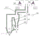
FIG. 1 is a schematic view of a first embodiment of the vertical pulverized coal boiler system according to the present invention;
FIG. 2 is a schematic diagram of the upstream flow equipment of the vertical pulverized coal boiler system of FIG. 1;
FIG. 3 is a schematic view of the downstream flow equipment of the vertical pulverized coal boiler system of FIG. 1;
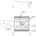
FIG. 4 is a schematic vertical sectional view of a powder circulating combustible gas generator, a dust-collecting heat exchange chamber, and a hearth bottom according to a first embodiment of the vertical powder boiler system;
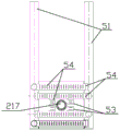
FIG. 5 is a schematic top view of the powder recycling combustible gas generator, the dust collecting heat exchange chamber and the bottom of the furnace shown in FIG. 4;
FIG. 6 is a schematic view showing the positional relationship between two parallel rows of air ducts and the upper openings of the grid, blind and extension ducts therebetween as shown in FIG. 5;
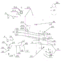
FIG. 7 is a schematic flow diagram of a second embodiment of the vertical pulverized fuel boiler system of the present invention;
FIG. 8 is a schematic diagram of the upstream equipment of a second embodiment of the novel vertical pulverized fuel boiler system of FIG. 7.
In the figure: 1 is a hearth, 2 is a powder circulating combustible gas generator, 3 is a powder feeding fan, 4 is a primary fan, 5 is a secondary fan, 6 is a powder material preparing bin, 7 is a dust collecting heat exchange chamber, 8 is an ash collecting hopper, 9 is a vertical ash discharging pipe, 10 is an ash discharging valve, 11 is a primary air chamber, 12 is an ignition cylinder, 13 is an ignition spray gun, 14 is a primary air pipe, 15 is a secondary air pipe, 16 is a high-energy igniter, 17 is a primary air branch pipe, 18 is an oil supply pipe, 19 is a waste heat boiler, 20 is a quick-cutting valve, 21 is a preheating combustion chamber, 211 is a fuel powder feeding pipe, 212 is a sand adding pipe, 213 is a feeding pipe, 214 is a sand adding hopper, 215 is a sand adding valve, 216 is a screw feeder, 217 is an extension pipeline, 22 is an air solidifying device, 23 is a rotary feeder, 24 is an oil regulating valve, 25 is an atomizing branch pipe, 26 is a blowing branch pipe, 27 is a loosening branch pipe, 28 is a return branch pipe, 29 is an atomizing valve, 30 is a purge valve, 31 is a return valve, 32 is a flow meter, 33 is a loose valve, 34 is a plurality of groups of preheated water heat exchangers, 35 is a buffer tank, 36 is a domestic water heat exchanger, 37 is a tertiary air preheater, 38 is a secondary air preheater, 39 is a tertiary air pipe, 40 is a tertiary air fan, 41 is a desulfurizing tower, 42 is a bag-type dust remover, 43 is an induced draft fan, 44 is a matched chimney, 45 is a front electric air door, 46 is a circulating flue gas pipe, 47 is a circulating flue gas fan, 48 is a circulating flue gas electric air door, 49 is high-temperature-resistant glass, 50 is a reserved threaded hole for installing a temperature sensor and a pressure sensor on an extension pipeline, 51 is a parallel air pipe, 52 is a grid pipe, 53 is a blind pipe, 54 is an air outlet hole, and 55 is auxiliary oil or an air gun.
Detailed Description
The first implementation mode comprises the following steps: as shown in fig. 1-6, the novel vertical powder boiler system comprises a furnace 1, a powder circulating combustible gas generator 2, a powder feeding fan 3, a primary air fan 4, a secondary air fan 5 and a flue, wherein the furnace 1 is cylindrical, the powder circulating combustible gas generator 2 comprises a preheating combustion chamber 21, a cyclone gas-solid separator 22 and a return feeder 23, which are sequentially connected in series to form a circulating fluidized bed type gas generating device, a fuel powder feeding pipe 211 and a sand feeding pipe 212 are arranged on the side wall of the lower part of the preheating combustion chamber 21, wherein the fuel powder feeding pipe 211 is connected with the outlet of the powder feeding fan 3, a fuel powder feeding pipe 213 is further arranged on the fuel powder feeding pipe 211, the feeding pipe 213 is connected with the discharge port at the bottom of the powder distribution bin 6 through a screw feeder 216 (of course, the screw feeder 2016 can also be replaced by a rotary valve, but not shown), the sand feeding hopper 214 is arranged at the top of the sand feeding pipe, and is provided with a sanding valve 215.
The method is characterized in that: 1 upper portion of furnace or top are equipped with pressure sensor or manometer, powder circulation combustible gas generator 2 sets up in 1 below of furnace, and 1 bottom of furnace is equipped with an album dirt heat transfer chamber 7, is equipped with the air distribution device between an album dirt heat transfer chamber 7 and the furnace 1, and an album dirt heat transfer chamber 7 bottom is equipped with a plurality of collection ash funnels 8 that center on the vertical central line evenly distributed of an album dirt heat transfer chamber 7, and every collection ash funnel 8 is big-end-up's back taper tubular, and every collection ash funnel 8 lower extreme all links there is vertical ash discharge pipe 9, all is equipped with dust valve 10 on every vertical ash discharge pipe 9. The gas outlet of the cyclone gas-solid separator 22 passes through the dust-collecting heat exchange chamber 7 through an extension pipe 217 and is introduced into the bottom of the hearth 1.
The preheating combustion chamber 21 is cylindrical, a side pipe is arranged at the top of the preheating combustion chamber and is communicated with an inlet of a cyclone gas-solid separator 22 through the side pipe, a gas outlet at the top of the cyclone gas-solid separator 22 is used as a gas discharge hole of the powder circulating combustible gas generator 2 and is communicated with the dust collection heat exchange chamber 7, the bottom of the cyclone gas-solid separator 22 is communicated with the lower part of the preheating combustion chamber 21 through a return feeder 23, a primary air chamber 11 is arranged at the bottom of the preheating combustion chamber 21, the primary air chamber 11 is communicated with an ignition cylinder 12, an ignition spray gun 13 is further arranged on the ignition cylinder 12, a primary air pipe 14 is arranged between the primary air chamber 11 and an outlet of the primary air fan 4, a secondary air pipe 15 is connected to the side wall of the dust collection heat exchange chamber 7, the secondary air pipe 15 is communicated with an outlet of the secondary air fan 5, and a.
The outer end of the ignition cylinder 12 is provided with a plurality of primary air branch pipes 17, the primary air branch pipes 17 are communicated with the primary air pipe 14, the outlet of the primary air fan 4 is communicated with the primary air chamber 11 through the primary air pipe 14, the plurality of primary air branch pipes 17 and the ignition cylinder 12, and the outlet at the front end of the ignition spray gun 13 is positioned in the ignition cylinder 12 and is positioned at the downstream of the outlet of the primary air branch pipe 17.
The front end of the ignition spray gun 13 can extend into the ignition cylinder 12, the rear end of the ignition spray gun is respectively provided with an oil inlet and a compressed air inlet, the oil inlet is communicated with a matched ignition oil pipe through an oil supply pipe 18 and a quick-cutting valve 20 and an oil regulating valve 24 which are connected on the oil supply pipe 18 in series, the matched compressed air pipe is connected with an atomization branch pipe 25, a purging branch pipe 26, a loosening branch pipe 27 and a material returning branch pipe 28, the atomization branch pipe 25 is provided with an atomization valve 29 and is communicated with the compressed air inlet at the rear end of the ignition spray gun 13, the purging branch pipe 26 is provided with a purging valve 30 and is communicated with the oil supply pipe 18 between the interfaces of the oil regulating valve 24 and; the material returning branch pipe 28 is provided with a material returning valve 31 and a flow meter 32 and is communicated with the material returning device 23, and the loosening branch pipe 27 is provided with a loosening valve 33 and a flow meter 32.
A two-stage linkage screw feeder 216 is arranged between the feeding pipe 213 and a discharge hole at the bottom of the powder material preparing bin 6. Therefore, on one hand, the combustible powder is convenient to feed, and on the other hand, the powder air can be prevented from blowing into the matched combustible powder bin.
A waste heat boiler 19 and a plurality of groups of preheating water heat exchangers 34 are arranged between the hearth 1 and the flue, the plurality of groups of preheating water heat exchangers are all provided with heat exchange coil pipes (not shown in the figure), the waste heat boiler 19 is connected with the shells of the plurality of groups of preheating water heat exchangers 34 in series to form a part of the flue together, the top of the waste heat boiler is provided with a buffer tank 35, the top of the buffer tank 35 is provided with a safety valve and an air release valve, the waste heat boiler 19 is internally provided with a plurality of groups of heat exchange pipes, one end of each heat exchange pipe is communicated with the bottom of the buffer tank,
the heat exchange coils of the multiple groups of preheating water heat exchangers 34 are sequentially connected to form a preheating water pipe (not shown in the figure), one end of the preheating water pipe is introduced into the buffer tank 35, the other end of the preheating water pipe is communicated with a matched high-pressure water supply pipe (not shown in the figure) through a water inlet valve, the gas flow direction of the flue is opposite to the water flow in the preheating water pipe, and the gas flow direction and the water flow in the preheating water pipe are in reverse heat exchange;
a plurality of groups of domestic water heat exchangers 36 are sequentially arranged at the downstream end of a flue formed by connecting shells of a plurality of groups of preheating water heat exchangers 34 in series, the shells of the domestic water heat exchangers 36 are connected in series to form a part of the flue, each domestic water heat exchanger 36 is internally provided with a heat exchange coil (not shown in the figure), the heat exchange coils are connected in series, a stop valve (not shown in the figure) is arranged between adjacent heat exchange coils, both sides of the stop valve are respectively provided with a water inlet pipe (not shown in the figure), each water inlet pipe and each water outlet pipe is provided with a valve (not shown in the figure), the heat exchange coils can be connected between a matched water inlet pipe (not shown in the figure) and a matched water outlet pipe (not shown in the figure) in series or respectively connected with a matched water inlet pipe (,
the flue downstream end that multiunit domestic water heat exchanger 36's casing concatenates is equipped with tertiary air preheater 37 and overgrate air preheater 38 in proper order, be equipped with heat transfer coil pipe (not shown in the figure) in above-mentioned tertiary air preheater 38 and the overgrate air preheater 37, the casing of tertiary air preheater 38 and overgrate air preheater 38's casing concatenate into the part of flue, be equipped with a plurality of tertiary tuber pipes 39 on the adapted furnace 1 lateral wall, above-mentioned tertiary tuber pipe 39 communicates with each other through tertiary air house steward and tertiary air preheater 38's heat exchange tube one end, the heat exchange tube other end of above-mentioned tertiary air preheater communicates with each other with the export of a tertiary air fan 40, heat transfer coil pipe in the overgrate air preheater concatenates between secondary air fan. Therefore, the waste heat of the flue gas can be fully utilized, and the energy conservation and the environmental protection are realized.
Be equipped with a plurality of drain pipes and trap (not shown in the figure) on the adapted steam trunk line, be equipped with the water intaking valve (not shown in the figure) on the adapted high pressure delivery pipe, be equipped with the level gauge (not shown in the figure) on the buffer tank 35, tertiary air preheater 38's casing and secondary air preheater 37's casing concatenate into flue downstream end and link gradually desulfurizing tower 41, sack cleaner 42, draught fan 43's export communicates with each other through pipeline and adapted chimney 44, be equipped with the observation window on the ignition barrel 12, be equipped with high temperature resistant glass 49 on the observation window, primary air fan 4, secondary air fan 5, tertiary air fan 40, send whitewashed fan 3, draught fan 43 to drive by inverter motor, through each fan amount of wind of speed control who adjusts inverter motor, be equipped with temperature sensor and pressure sensor on the primary air chamber 11, an oxygen content sensor and a temperature sensor, an upper temperature sensor, a middle temperature sensor and a lower temperature sensor (not shown in the figure) are respectively arranged on the side wall of the preheating combustion chamber 21, a pressure gauge and a pressure sensor are arranged at the outlet of the powder feeding fan 3,
the utility model discloses a fire detection device for a fire detection furnace, including furnace 1, camera pipe, fire detection camera, high temperature resistant glass sealing plate, purging pipe, matched compressed air pipe, purging valve, compressed air pipe, fire detection camera, fire detection.
The flue at the upstream of the desulfurizing tower 41 is also provided with a front electric air door 45, the flue at the upstream of the front electric air door 45 is provided with a circulating flue gas pipe 46, and the circulating flue gas pipe 46 is communicated with the secondary air pipe 15 through a circulating flue gas fan 47, a circulating flue gas electric air door 48 and the flowmeter 32.
The powder circulating combustible gas generator 2 is arranged on one side below the hearth, the extension pipeline 217 is bent twice, penetrates through the dust collection heat exchange chamber 7 and then is introduced into the center of the bottom of the hearth 1, and a temperature sensor and a pressure sensor are arranged at the downstream bent part on the extension pipeline 217. Fig. 4 shows a screw hole 50 provided in the extension pipe for mounting the temperature sensor and the pressure sensor.
Two rows of grid pipes 52 are arranged in the dust collection heat exchange chamber 7, the two rows of grid pipes 52 are respectively arranged on two sides of an upper port of the extension pipeline 217, two blind pipes 53 are respectively communicated with the inner side walls of the two grid pipes 52 close to the upper port of the extension pipeline 217, the blind pipes 53 and the grid pipes 52 communicated with the blind pipes enclose the upper port of the extension pipeline 217 in the middle, one surface of each grid pipe 52 and one surface of each blind pipe 53 facing the hearth 1 are provided with a plurality of air outlet holes 54, two rows of parallel air pipes 51 are arranged on two sides of the dust collection heat exchange chamber 7, the two rows of parallel air pipes 51 are communicated with the secondary air pipe 15, and each grid pipe 51 is communicated with one row or two rows of parallel air pipes 51 to.
Note: the extension pipe 217 of fig. 4-6 is slightly different from the extension pipe 217 of fig. 1 and 2, and the bend of the extension pipe 217 of fig. 1 and 2 is a rounded elbow. The bends in the extension pipe 217 of fig. 4-6 are preferably right angle bends, but are not inconsistent.
The third embodiment is as follows: as shown in fig. 7 and 8, the powder circulation combustible gas generator 22 is arranged right below the hearth 1. The ash collecting funnel 8, the vertical ash discharge pipe 9 and the ash discharge valve 10 are arranged on the dust collection heat exchange chamber 7 around the vertical center of the dust collection heat exchange chamber 7. And an auxiliary oil or air gun 55 is also arranged on the side wall of the lower part of the hearth 1. The auxiliary oil or air gun 55 is communicated with the matched ignition oil pipe through a valve and a pipeline, and the rest structures are omitted as shown in the first embodiment.
The third embodiment is as follows: the device also comprises a programmable controller (not shown in the figure), a memory (not shown in the figure) and a touch screen (not shown in the figure), wherein the memory and the touch screen are respectively connected with the programmable controller, all valves are electric valves, all electric valves and variable frequency motors of all fans are connected with a control signal output end of the programmable controller, all temperature sensors, pressure sensors, flowmeters, liquidometers, oxygen content sensors and fire detection cameras are connected with a signal input end of the programmable controller, and other structures are as described in the first embodiment, and the figure is omitted.
The utility model discloses embodiment one novel vertical powder boiler system's application method, including following step:
first, preparation before ignition
Firstly, opening a release valve and a water inlet valve on the buffer tank 35, injecting water into the buffer tank 35 to enable the water quantity inside the buffer tank to reach 40-50% of the total volume of the buffer tank 35, and opening each drain valve.
And secondly, installing the ignition spray gun 13 in place and checking a fire detection camera.
Thirdly, opening the sand adding valve 215, and adding the quartz sand into the preheating combustion chamber 21 through the sand adding hopper 214, so that the quartz sand is naturally accumulated in the preheating combustion chamber 21 to 50-70 cm high.
Opening the material returning valve 31 and the loosening valve 33 to make the flow speed of the material returning air reach twice that of the loosening air (the air quantity of the material returning is 40M)3H, adjusting the loosening air quantity to be 20M3/h),
Starting the primary air fan 4, leading the quartz sand in the preheating combustion chamber 21 to be in a fluidized state by introducing primary air, starting and adjusting the induced draft fan 43 to keep the pressure at the upper part or the top part of the hearth 1 to be 0-100Pa,
if the ignition is the first ignition of the novel vertical powder boiler system, the powder feeding fan 3 is started, and the rotating speed of the powder feeding fan 3 is adjusted to 10% of the full-load rotating speed;
if the ignition is not the first ignition, the next step is directly carried out,
seventhly, purging the hearth 1, starting the induced draft fan 43 and performing secondary operationThe blower 5 and the tertiary blower 40 make the secondary blower 5 and the tertiary blower 40 rotate at the rotation speed of 30 percent of the full load rotation speed, the hearth 1 is swept for 5 to 10 minutes, and the rotation speed of the secondary blower 5 is adjusted to 15 percent of the full load rotation speed (4000M)3H) adjusting the rotational speed of the tertiary air blower 40 to 10% of its full load rotational speed (3000M)3/h),
Adjusting the rotating speed of the primary fan 4 to slowly rise to about 40 percent of the full load rotating speed (the wind speed is about 1200M)3And/h), keeping the quartz sand in the preheating combustion chamber 21 in a fluidized state, and adjusting the rotating speed of the induced draft fan 43 to keep the pressure in the hearth 1 within the range of 0-minus 100 Pa.
II, oil ignition:
(1) opening the purge valve 30 and the atomization valve 29 to purge for 1 minute, then closing the purge valve 30, after closing the purge valve 30, starting the high-energy igniter, simultaneously opening the quick-cut valve 20 and opening the oil regulating valve 24, after 10 seconds, automatically cutting off the high-energy igniter 16, at the moment, observing whether the front end of the ignition spray gun 13 has open fire or not through an observation window by a worker, if the front end of the ignition spray gun 13 has no fire, indicating that the ignition fails, rapidly closing the quick-cut valve 20 and the oil regulating valve 24, opening the purge valve 30 to purge, after purging for 1 minute, closing the purge valve 30, repeating the steps until the front end of the ignition spray gun 13 has open fire, and successfully igniting,
(2) after ignition is successful, keeping the opening degree of the oil regulating valve 24 unchanged at 30 percent, and increasing the rotating speed of the primary air fan 4 to 50-70 percent of the full-load rotating speed thereof to keep the temperature of the primary air chamber 11 within 850 ℃; the temperature is continuously increased, and the temperature increasing speed of the preheating combustion chamber 21 is controlled below 400 ℃/h.
Thirdly, igniting powder:
if the ignition is carried out for the first time, directly entering the next step, if the ignition is not carried out for the first time, starting the powder feeding fan 3 after the ignition is successfully carried out, slowly starting the powder feeding fan, and increasing the opening degree to about 10%;
when the temperature of the preheating combustion chamber reaches 600 ℃ (± 50 ℃), restarting a hearth purging program:
starting the induced draft fan 43, the secondary fan 5 and the tertiary fan 40, and adjusting the variable frequency motors driving the secondary fan 5 and the tertiary fan 40 to ensure that the corresponding fans rotate at 30 percent of the respective full load rotating speedRotating at the rotating speed, blowing the hearth 1 for 5-10 minutes, and adjusting the rotating speed of the secondary fan 5 to 15 percent of the full load rotating speed (4000M)3H) adjusting the rotational speed of the tertiary air blower 40 to 10% of its full load rotational speed (3000M)3/h),
After the purging is finished, starting the screw feeder 216 to enable the rotating speed of the screw feeder 216 to reach 5% of the full-load rotating speed, adjusting the rotating speed of the powder feeding fan 3 to 45% of the full-load rotating speed, adjusting the rotating speed of the primary fan 4 to 65% of the full-load rotating speed, adjusting the rotating speed of the secondary fan 5 to 15% of the full-load rotating speed, adjusting the rotating speed of the tertiary fan 40 to 10% of the full-load rotating speed, adjusting the rotating speed of the induced draft fan 43 to 20% of the full-load rotating speed, continuing to burn and heat,
and thirdly, when the temperature of the preheating combustion chamber 21 rises to 800 ℃ of 700-.
And fourthly, when the temperature sensed by the temperature sensor on the rear elbow reaches about 700 ℃, the temperature sensed by the temperature sensor at the upper part or the top part of the hearth 1 reaches 70-80 ℃, and the temperatures sensed by the upper, middle and lower temperature sensors of the preheating combustion chamber 21 are all in the range of 850 ℃ and 900 ℃, adding auxiliary oil or air guns 55, when the temperature measuring point at the lower part of the hearth reaches 300 ℃, trying to add combustible powder, and when the fire is detected and displayed in the hearth, stopping feeding of the auxiliary oil or air guns 55. Putting combustible powder into the furnace, gasifying and running the combustible powder, and entering an ignition stage of a hearth 1;
the method comprises the following specific steps:
1) the top pressure of the hearth 1 is kept in the range of-90 pa to-110 pa by adjusting the rotating speeds of the secondary fan 5, the tertiary fan 40 and the induced draft fan 43; 2) starting the auxiliary oil or air gun 55 at the lower part of the hearth, trying to put in combustible powder when the temperature of the temperature measuring point at the lower part of the hearth reaches about 300 ℃, and stopping the auxiliary oil or air gun 55 when the fire is detected in the hearth.
3) Adjusting the rotating speed of the powder feeding fan 3 to 80% of the full-load rotating speed, observing whether the outlet pressure of the powder feeding fan 3 reaches the design pressure, observing the temperature rise condition of the preheating combustion chamber 21, if the hearth is on fire in 60 seconds, the oxygen content is reduced, and when small positive pressure exists, judging that the ignition of the thrown combustible powder is normal, and if the hearth is not on fire in 60 seconds, immediately stopping the operation of the screw feeder 216 and the powder feeding fan 3 to purge the hearth 1.
Starting the induced draft fan 43, the secondary fan 5 and the tertiary fan 40, adjusting the variable frequency motors driving the secondary fan 5 and the tertiary fan 40 to enable the corresponding fans to rotate at the rotation speed of 30% of the full load rotation speed of each fan, purging the hearth for 5-10 minutes, and adjusting the rotation speed of the secondary fan 5 to 15% (4000M) of the full load rotation speed of the secondary fan 53H) adjusting the rotational speed of the tertiary air blower 40 to 10% of its full load rotational speed (3000M)3H), adding combustible powder again for ignition at an interval of more than 10 minutes until the ignition is normal;
fourthly, igniting the powder to finish subsequent work:
firstly, after the combustible powder is normally put into fire, immediately regulating the rotating speed of a secondary fan 5 to 30-35% of the full-load rotating speed, regulating the rotating speed of a tertiary fan 40 to 20-25% of the full-load rotating speed, keeping the oxygen content in a hearth within the range of 2-6%, and controlling the water level and the steam temperature of a buffer tank 35 according to the steam pressure rising condition of a main pipeline for matching steam;
secondly, after the combustible powder is fed and ignited normally, when the temperature of the flue gas reaches above 90 ℃, the personnel in the subsequent posts are immediately contacted to put in the desulfurizing tower 41 and the bag-type dust collector 42, so that the environmental protection parameters are not overproof;
and thirdly, monitoring the temperature of the preheating combustion chamber 21 from the initial ignition stage of the combustible powder feeding to the whole operation period, so that the temperatures sensed by the upper temperature sensor, the middle temperature sensor and the lower temperature sensor on the preheating combustion chamber 21 are all kept at 950 ℃ of 800 plus materials, properly reducing the input amount of the combustible powder when the temperature is high, properly increasing the input amount of the combustible powder when the temperature is low, and properly increasing the air amounts of primary air, secondary air and tertiary air to ensure the full combustion of the combustible powder.
Claims (9)
1. The utility model provides a novel vertical powder boiler system, includes furnace, powder circulation combustible gas generator, send whitewashed fan, secondary fan and flue, furnace is the cylindric, powder circulation combustible gas generator includes preheating combustion chamber, whirlwind gas-solid separator and returning charge ware, and the three establishes ties in order into circulation fluidized bed formula gas generating device, be equipped with fuel powder inlet pipe and sand feeding pipe on the preheating combustion chamber lower part lateral wall, wherein the fuel powder inlet pipe links to each other with the export that sends the whitewashed fan, and still is equipped with a feed pipe on the fuel powder inlet pipe, and this feed pipe passes through screw feeder or rotary valve and links to each other with the discharge gate of powder adapted feed bin bottom, the sand feeding pipe top is equipped with the sand hopper to be equipped with the sand valve, its characterized in that: the furnace is provided with a pressure sensor or a pressure gauge, the powder circulating combustible gas generator is arranged below the furnace, the bottom of the furnace is provided with a dust collecting heat exchange chamber, an air distribution device is arranged between the dust collecting heat exchange chamber and the furnace, the bottom of the dust collecting heat exchange chamber is provided with a plurality of dust collecting funnels which are uniformly distributed around the vertical central line of the dust collecting heat exchange chamber, each dust collecting funnel is in the shape of an inverted cone with a large top and a small bottom, the lower end of each dust collecting funnel is connected with a vertical ash discharge pipe, each vertical ash discharge pipe is provided with an ash discharge valve, a gas outlet of the cyclone gas-solid separator penetrates through the dust collecting heat exchange chamber through an extension pipeline and is led,
the preheating combustion chamber is cylindrical, a side pipe is arranged at the top of the preheating combustion chamber and is communicated with an inlet of a cyclone gas-solid separator through the side pipe, a top gas outlet of the cyclone gas-solid separator is used as a gas discharge hole of the powder circulating combustible gas generator and is communicated with the dust collection heat exchange chamber, the bottom of the cyclone gas-solid separator is communicated with the lower part of the preheating combustion chamber through a return feeder, a primary air chamber is arranged at the bottom of the preheating combustion chamber and is communicated with an ignition barrel, an ignition spray gun is further arranged on the ignition barrel, a primary air pipe is arranged between the primary air chamber and an outlet of the primary air fan, a secondary air pipe is connected to the side wall of the dust collection heat exchange chamber and is communicated with an outlet of the secondary air fan, and a high-energy igniter is further arranged on.
2. The vertical pulverized-fuel boiler system as claimed in claim 1, wherein: the ignition spray gun is characterized in that a plurality of primary air branch pipes are arranged at the outer end of the ignition cylinder and are communicated with the primary air pipe, the outlet of the primary air fan is communicated with the primary air chamber through the primary air pipe, the plurality of primary air branch pipes and the ignition cylinder, and the outlet at the front end of the ignition spray gun is positioned in the ignition cylinder and is positioned at the downstream of the outlet of the primary air branch pipe.
3. The vertical pulverized-fuel boiler system as claimed in claim 1, wherein: the front end of the ignition spray gun can extend into the ignition cylinder, the rear end of the ignition spray gun is respectively provided with a fuel inlet and a compressed air inlet, the fuel inlet is communicated with an adapted ignition fuel pipe through an oil supply or natural gas pipe and a quick-cutting valve and a fuel regulating valve which are connected in series on the oil supply or natural gas pipe, the adapted compressed air pipe is connected with an atomizing branch pipe, a purging branch pipe, a loosening branch pipe and a material returning branch pipe, the atomizing branch pipe is provided with an atomizing valve and is communicated with the compressed air inlet at the rear end of the ignition spray gun, and the purging branch pipe is provided with a purging valve and is communicated with the oil supply or natural gas pipe between the fuel regulating valve and an; the material returning branch pipe is provided with a material returning valve and a flowmeter and is communicated with the material returning device, and the loosening branch pipe is provided with a loosening valve and a flowmeter.
4. The vertical pulverized-fuel boiler system as claimed in claim 1, wherein: the utility model discloses a stove, including the stove, the stove is equipped with the heat transfer room, the indoor setting of collection dirt heat transfer is equipped with two rows of bars pipes, and two rows of bars pipes set up respectively in extension pipeline upper port both sides, and it has two blind pipes to communicate respectively on two bars intraductal walls of pipe that press close to extension pipeline upper port, and the blind pipe and the bars pipe that are linked together enclose the upper port of extension pipeline in the centre, and every bars pipe and blind pipe are opened towards furnace one side and are had a plurality of exhaust vents, collection dirt heat transfer room both sides are equipped with two parallel tuber pipes, and two are listed as parallel tuber pipe and.
5. The vertical pulverized-fuel boiler system as claimed in claim 4, wherein: the powder circulating combustible gas generator is arranged on one side or right below the hearth, the extension pipeline is bent twice and passes through the dust-collecting heat exchange chamber to be led into the center of the bottom of the hearth, and a temperature sensor and a pressure sensor are arranged at the downstream bent part on the extension pipeline.
6. The vertical pulverized-fuel boiler system as claimed in claim 5, wherein: and the side wall of the lower part of the hearth is also provided with an auxiliary oil or air gun which is communicated with a matched ignition fuel pipe through a valve and a pipeline.
7. The vertical pulverized-fuel boiler system as claimed in claim 6, wherein: the matched steam main pipeline is provided with a plurality of drain pipes and drain valves, a water inlet valve is arranged on a matched high-pressure water supply pipe, a waste heat boiler and a plurality of groups of preheating water heat exchangers are arranged between the hearth and the flue, the top of the waste heat boiler is provided with a buffer tank, a liquid level meter is arranged on the buffer tank, a plurality of groups of domestic water heat exchangers are sequentially arranged at the downstream end of the flue formed by serially connecting the shells of the preheating water heat exchangers, a tertiary air preheater is sequentially arranged at the downstream end of the flue formed by serially connecting the shells of the groups of domestic water heat exchangers, the other end of the heat exchange pipe of the tertiary air preheater is communicated with the outlet of a tertiary air fan, the shell of the tertiary air preheater and the downstream end of the flue formed by serially connecting the shell of the secondary air preheater are sequentially connected with a desulfurizing tower, a, the observation window is provided with high temperature resistant glass, the primary fan, the secondary fan, the tertiary fan, the powder feeding fan and the draught fan are all driven by a variable frequency motor, the air quantity of each fan is controlled by adjusting the rotating speed of the variable frequency motor, the primary air chamber is provided with a temperature sensor and a pressure sensor, the upper part or the top of the hearth is provided with the pressure sensor, an oxygen content sensor and the temperature sensor, the side wall of the preheating combustion chamber is respectively provided with an upper temperature sensor, a middle temperature sensor and a lower temperature sensor, the outlet of the powder feeding fan is provided with a pressure gauge and a pressure sensor,
furnace middle part/or upper portion are equipped with the camera pipe, and the camera is examined to camera pipe outer end is equipped with the fire, and the camera pipe front end is equipped with high temperature resistant glass shrouding, still is equipped with the pipe that sweeps of directional high temperature resistant glass shrouding medial surface on camera pipe one side furnace wall, should sweep the pipe and communicate with each other with adapted compressed air pipe through the purge valve.
8. The vertical pulverized-fuel boiler system as claimed in claim 7, wherein: and a front electric air door is further arranged on the flue at the upper part of the desulfurizing tower, a circulating flue gas pipe is arranged on the flue at the upper part of the front electric air door, and the circulating flue gas pipe is communicated with a secondary air pipe through a circulating flue gas fan, the circulating flue gas electric air door and a flowmeter.
9. The vertical pulverized-fuel boiler system as claimed in claim 7, wherein: the device also comprises a programmable controller, a memory and a touch screen, wherein the memory and the touch screen are respectively connected with the programmable controller, all valves are electric valves, all electric valves and variable frequency motors of all fans are connected with a control signal output end of the programmable controller, and all temperature sensors, pressure sensors, flowmeters, liquid level meters, oxygen content sensors and fire detection cameras are connected with a signal input end of the programmable controller.
Priority Applications (1)
| Application Number | Priority Date | Filing Date | Title |
|---|---|---|---|
| CN202020047583.4U CN212057227U (en) | 2020-01-09 | 2020-01-09 | Novel vertical powder boiler system |
Applications Claiming Priority (1)
| Application Number | Priority Date | Filing Date | Title |
|---|---|---|---|
| CN202020047583.4U CN212057227U (en) | 2020-01-09 | 2020-01-09 | Novel vertical powder boiler system |
Publications (1)
| Publication Number | Publication Date |
|---|---|
| CN212057227U true CN212057227U (en) | 2020-12-01 |
Family
ID=73535323
Family Applications (1)
| Application Number | Title | Priority Date | Filing Date |
|---|---|---|---|
| CN202020047583.4U Active CN212057227U (en) | 2020-01-09 | 2020-01-09 | Novel vertical powder boiler system |
Country Status (1)
| Country | Link |
|---|---|
| CN (1) | CN212057227U (en) |
Cited By (1)
| Publication number | Priority date | Publication date | Assignee | Title |
|---|---|---|---|---|
| CN112833422A (en) * | 2021-03-04 | 2021-05-25 | 河北工业大学 | Spark ignition type igniter for gas fuel and ignition method |
-
2020
- 2020-01-09 CN CN202020047583.4U patent/CN212057227U/en active Active
Cited By (2)
| Publication number | Priority date | Publication date | Assignee | Title |
|---|---|---|---|---|
| CN112833422A (en) * | 2021-03-04 | 2021-05-25 | 河北工业大学 | Spark ignition type igniter for gas fuel and ignition method |
| CN112833422B (en) * | 2021-03-04 | 2024-03-08 | 河北工业大学 | Electric spark igniter for gas fuel and ignition method |
Similar Documents
| Publication | Publication Date | Title |
|---|---|---|
| CN111102553A (en) | Novel vertical powder boiler system and using method thereof | |
| CN1328539C (en) | Medium and small sized industrial pulverized-coal fired boiler | |
| CN212057227U (en) | Novel vertical powder boiler system | |
| CN103900112B (en) | The solid particle fuel cooking stove of multifunctional efficient | |
| CN110513675A (en) | A kind of efficient reuse straw bundle firing method of flue gas | |
| CN208186363U (en) | A kind of system for pyrolyzing and burning of smoke backflow formula | |
| CN207865695U (en) | A kind of dual-purpose boiling type hot-blast stove of novel bottle coal | |
| CN110319434B (en) | Biomass forming particle combustion integrated furnace for flue-cured tobacco | |
| CN103712226B (en) | It is applied to the circulation pulverized coal preparation system of middle-size and small-size industrial coal powder boiler | |
| CN205782851U (en) | A kind of biological particles combustion furnace | |
| CN209688813U (en) | Couple the integral type chain furnace of coal dust gasification and burning | |
| CN202141190U (en) | Biomass energy hot-blast stove | |
| CN215176011U (en) | Biomass particle combustion furnace for flue-cured tobacco | |
| CN102261739A (en) | Biomass energy hot blast stove | |
| CN105509472B (en) | A kind of sintering ignition device using coal dust as fuel | |
| CN211060092U (en) | Steam and hot air integrated machine | |
| CN208952409U (en) | A kind of automatic removing dust formula rice husk hot-blast stove | |
| CN104197733B (en) | Regenerative cycles device in Gas heating furnace high-temperature burns carbon distribution device and technique | |
| CN103900100B (en) | The air feed system of solid particle fuel cooking stove | |
| CN206269146U (en) | Radiant tube incinerator | |
| CN106895436B (en) | The device that glows of the powdered carbon fast low temperature burning of biomass molding fuel burning device | |
| CN207635348U (en) | A kind of incineration flue gas of household garbage process integrated system | |
| CN206145692U (en) | Pulverized coal boiler furnace soot blower | |
| CN206145665U (en) | Pulverized coal boiler soot blower system | |
| CN105588114A (en) | Vertical type semi-gasification biomass burning boiler |
Legal Events
| Date | Code | Title | Description |
|---|---|---|---|
| GR01 | Patent grant | ||
| GR01 | Patent grant |