CN212049911U - Production of woollen sweater is with wastrel yarn recovery unit - Google Patents
Production of woollen sweater is with wastrel yarn recovery unit Download PDFInfo
- Publication number
- CN212049911U CN212049911U CN202020265899.0U CN202020265899U CN212049911U CN 212049911 U CN212049911 U CN 212049911U CN 202020265899 U CN202020265899 U CN 202020265899U CN 212049911 U CN212049911 U CN 212049911U
- Authority
- CN
- China
- Prior art keywords
- vertical plate
- roll
- wind
- base
- belt wheel
- Prior art date
- Legal status (The legal status is an assumption and is not a legal conclusion. Google has not performed a legal analysis and makes no representation as to the accuracy of the status listed.)
- Active
Links
Images


Landscapes
- Yarns And Mechanical Finishing Of Yarns Or Ropes (AREA)
Abstract
The utility model relates to a knitting wool recovery plant technical field, concretely relates to woollen sweater production is with wastrel yarn recovery unit. The winding device comprises a base, wherein a vertical plate is fixed on the upper surface of the base, two groups of symmetrically arranged rotation recovery mechanisms are arranged on the base and the vertical plate, each rotation recovery mechanism comprises a driving motor and a winding roll, the driving motor is fixed on the base on the left side of the vertical plate, a first belt wheel is arranged on an output shaft of the driving motor, a bearing is arranged on the vertical plate, and a rotating shaft is connected in the bearing; the utility model discloses a reciprocal lead screw linkage of pivot band pulley, then reciprocating motion about reciprocating slide carries out in the bar groove to can be with the even winding of yarn on the woollen sweater wastrel on the wind-up roll, improved the roughness of yarn on the wind-up roll, and can eliminate static to the line ball of rolling, its effect is excellent, and the practicality is strong.
Description
Technical Field
The utility model relates to a knitting wool recovery plant technical field, concretely relates to woollen sweater production is with wastrel yarn recovery unit.
Background
In the production process of the woolen sweater, defective products are inevitable. At present, the woolen sweater defective products are treated by mainly removing the defective products through a simple recovery device and then rolling the defective products.
For example, the utility model discloses a device that is used for woollen sweater wastrel yarn to retrieve is just disclosed for CN206477075U, comprising a base plate, there are left side rotation recovery platform and woollen sweater to place the box in proper order from a left side to the right side in the top of bottom plate, there are first backup pad and second backup pad at the front end of left side rotation recovery platform top and the rear end at top fixed mounting respectively, spacing hole has been seted up to the side of first backup pad, the side fixed mounting of second backup pad has the stopper, the bottom fixed mounting of second backup pad inner chamber has the motor to press from both sides, the side fixed mounting that the motor pressed from both sides has driving motor, driving motor's output shaft fixedly connected with runs through second backup pad and stopper in proper order and extends to the drive roll of left side rotation. The device drives the driven roller to rotate through the motor, so that the yarns of the woolen sweater are recovered, but the device is wound intensively when the yarns are recovered, and the yarns cannot be uniformly wound on the driven roller. In addition, the woollen sweater can make the surface of knitting wool produce a large amount of static because of frictional action at the in-process of taking out stitches, if can not get rid of the static on woollen sweater surface, not only can influence subsequent rolling quality, the easy dust that adsorbs in the air of clew of retrieving moreover, need wash when using again. Therefore, aiming at the defects of the existing device, the invention provides the recovery device which not only can uniformly wind and roll the woolen sweater, but also can effectively eliminate static on the woolen yarns, and the technical problem to be solved is solved.
SUMMERY OF THE UTILITY MODEL
The utility model aims to solve the technical problem that a woollen sweater production is with wastrel yarn recovery unit has been designed to it is inhomogeneous at the recovery in-process winding to solve the woollen sweater wastrel, and the clew after the winding has a large amount of static not enough.
The utility model discloses a realize through following technical scheme:
a defective yarn recovery device for woolen sweater production comprises a base, wherein a vertical plate is fixed on the upper surface of the base, and two groups of symmetrically arranged rotary recovery mechanisms are arranged on the base and the vertical plate;
wherein, the rotary recovery mechanism comprises a driving motor and a wind-up roll, the driving motor is fixed on a base on the left side of a vertical plate, a first belt wheel is arranged on an output shaft of the driving motor, a bearing is arranged on the vertical plate, a rotating shaft is connected in the bearing, a second belt wheel is arranged at the left end of the rotating shaft, a first belt is arranged between the first belt wheel and the second belt wheel, a third belt wheel is arranged on the rotating shaft on the right side of the vertical plate, the wind-up roll is arranged at the right end of the rotating shaft, a cross arm is arranged on the vertical plate above the wind-up roll, a strip-shaped groove is arranged on the lower surface of the cross arm, a reciprocating screw rod is rotatably arranged in the strip-shaped groove, a rotating groove is arranged at the left end of the strip-shaped groove, a fourth belt wheel is arranged on the reciprocating screw rod in the, the winding roller is characterized in that a reciprocating slide block is arranged on the reciprocating lead screw, a threaded hole matched with the reciprocating lead screw is formed in the left side surface and the right side surface of the reciprocating slide block, the lower end of the reciprocating slide block is connected with a U-shaped rotating frame, two rotating wheels are arranged in the U-shaped rotating frame in a rotating mode and are arranged in an up-and-down symmetrical mode, the lower end of the U-shaped rotating frame, close to one side of the winding roller, is connected with a convex plate, a water absorption sponge is arranged on the convex plate, and a through.
As a further improvement of the scheme, the wind-up roll is in a circular truncated cone shape with a wide left part and a narrow right part, and two ends of the wind-up roll are provided with circular baffles; the winding roller is designed into a circular truncated cone shape, so that the yarn after winding is completed can be taken down conveniently, and the circular baffle plate can prevent the yarn from falling off from the two ends of the winding roller in the winding process and influence on subsequent winding.
As a further improvement of the above scheme, a circular baffle at the right end of the wind-up roll is detachably connected to the wind-up roll, a connecting screw hole is formed in the right end face of the wind-up roll, a circular hole is formed in the circular baffle at the right end, and fixing bolts are arranged on the connecting screw hole and the circular hole; can be convenient for directly take off the clew after the rolling is accomplished from the wind-up roll through connecting the circular baffle on right side is detachable, need not to change the wind-up roll.
As a further improvement of the scheme, the circumferential surfaces of the two rotating wheels are provided with semi-circular grooves, and the semi-circular grooves on the two rotating wheels form a limiting hole with the diameter larger than that of the yarn; the upper semi-circular grooves of the two rotating wheels can limit the yarn and prevent the yarn from deviating from the rotating wheels.
As a further improvement of the above scheme, the water absorption sponge is absorbed with a clothes softener water solution; the water solution of the softener for adsorbing clothes in the water-absorbing sponge can effectively eliminate static electricity, and the effect of the water solution is better than that of water.
Has the advantages that:
1. compared with the prior art, the utility model, through the reciprocal lead screw linkage of pivot band pulley, then reciprocating motion about reciprocating slide carries out in the bar groove to can be with the even winding of yarn on the woollen sweater wastrel on the wind-up roll, improved the roughness of yarn on the wind-up roll.
2. By arranging the two rotating wheels, when yarns on the woolen sweater defective goods pass through the two rotating wheels, the two rotating wheels can rotate along with the yarns, so that the friction between the woolen sweater and the surfaces of the rotating wheels is reduced, and the static electricity generated by the friction is reduced to a certain extent; in addition, the yarns are in contact with the water-absorbing sponge before being wound on the winding roller, and the water solution of the clothes softener on the water-absorbing sponge can be coated on the surfaces of the yarns, so that a large amount of static generated by friction in the process of removing the woolen sweater, and the defect that the recovered clew absorbs dust in the air in a large amount due to the static is effectively overcome.
Drawings
In order to more clearly illustrate the technical solutions of the embodiments of the present invention, the drawings used in the description of the embodiments will be briefly introduced below, and it is obvious that the drawings in the following description are only some embodiments of the present invention, and it is obvious for those skilled in the art that other drawings can be obtained according to these drawings without creative efforts.
Fig. 1 is a first angular perspective view of the present invention;
fig. 2 is a second perspective view of the present invention;
FIG. 3 is a perspective view of the cross arm of the present invention;
FIG. 4 is a perspective view of the reciprocating slider, the U-shaped rotating frame and other structures of the present invention;
fig. 5 is an assembly view of the wind-up roll in embodiment 2.
Detailed Description
In order to make the technical solutions better understood by those skilled in the art, the technical solutions in the embodiments of the present application will be clearly and completely described below with reference to the drawings in the embodiments of the present application, and it is obvious that the described embodiments are only partial embodiments of the present application, but not all embodiments. All other embodiments, which can be derived by a person skilled in the art from the embodiments given herein without making any creative effort, shall fall within the protection scope of the present application.
It should be noted that the terms "first," "second," and the like in the description and claims of this application and in the drawings described above are used for distinguishing between similar elements and not necessarily for describing a particular sequential or chronological order. It should be understood that the data so used may be interchanged under appropriate circumstances such that embodiments of the application described herein may be used. Furthermore, the terms "comprises," "comprising," and "having," and any variations thereof, are intended to cover a non-exclusive inclusion, such that a process, method, system, article, or apparatus that comprises a list of steps or elements is not necessarily limited to those steps or elements expressly listed, but may include other steps or elements not expressly listed or inherent to such process, method, article, or apparatus.
In this application, the terms "upper", "lower", "left", "right", "front", "rear", "top", "bottom", "inner", "outer", "middle", "vertical", "horizontal", "lateral", "longitudinal", and the like indicate orientations or positional relationships based on the orientations or positional relationships shown in the drawings. These terms are used primarily to better describe the invention and its embodiments, and are not intended to limit the indicated devices, elements or components to a particular orientation or to be constructed and operated in a particular orientation.
Moreover, some of the above terms may be used to indicate other meanings besides the orientation or positional relationship, for example, the term "on" may also be used to indicate some kind of attachment or connection relationship in some cases. The specific meaning of these terms in the present invention can be understood by those of ordinary skill in the art as appropriate.
Furthermore, the terms "mounted," "disposed," "provided," "connected," and "sleeved" are to be construed broadly. For example, it may be a fixed connection, a removable connection, or a unitary construction; can be a mechanical connection, or an electrical connection; may be directly connected, or indirectly connected through intervening media, or may be in internal communication between two devices, elements or components. The specific meaning of the above terms in the present invention can be understood according to specific situations by those skilled in the art.
It should be noted that the embodiments and features of the embodiments in the present application may be combined with each other without conflict. The present application will be described in detail with reference to the accompanying examples and figures 1-5.
Example 1
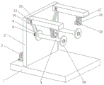
Embodiment 1 introduces a production of woollen sweater with wastrel yarn recovery unit, major structure includes base 1, is fixed with riser 2 at the upper surface of base 1 to be provided with two sets of rotation recovery mechanisms on base 1 and riser 2, and with two sets of rotation recovery mechanism symmetry settings.
Specifically, the rotation recovery mechanism in this embodiment includes drive motor 3 and wind-up roll 4, fixes drive motor 3 on base 1 on the left of riser 2 to be provided with first band pulley 5 on drive motor 3's output shaft, be provided with the bearing (not marking in the figure) on the riser, be connected with pivot 6 in its bearing, be provided with second band pulley 7 at the left end of pivot 6, be provided with first belt 8 between first band pulley 5 and second band pulley 7, realize the rotation of pivot 6 through the effect of first belt 8.
And a third belt wheel 9 is arranged on the rotating shaft 6 on the right side of the vertical plate 2, and the winding roller 4 is arranged at the right end of the rotating shaft 6. A cross arm 10 is arranged on the vertical plate 2 above the winding roller 4, a strip-shaped groove 101 is arranged on the lower surface of the cross arm 10, a reciprocating screw rod 12 is rotatably arranged in the strip-shaped groove 101, and two ends of the reciprocating screw rod 12 are connected with bearings (not shown in the figure) on the left side wall and the right side wall of the strip-shaped groove 101. A rotating groove 102 is arranged at the left end of the strip-shaped groove 101, a fourth belt wheel 13 is arranged on the reciprocating screw rod 12 positioned in the rotating groove 102, a second belt 14 is arranged between the third belt wheel 9 and the fourth belt wheel 13, and the rotating shaft 6 and the reciprocating screw rod 12 synchronously rotate under the action of the second belt 14. The reciprocating screw rod 12 is provided with a reciprocating slide block 15, the left side and the right side of the reciprocating slide block 15 are provided with threaded holes (not marked in the figure), and the reciprocating slide block 15 can move left and right along the strip-shaped groove 101 through the matching between the threaded holes and the reciprocating screw rod 12. Meanwhile, the lower end of the reciprocating slide block 15 is connected with a U-shaped rotating frame 16, two rotating wheels 17 are rotatably arranged in the U-shaped rotating frame 16, the two rotating wheels 17 are arranged in a vertically symmetrical mode, in order to prevent the yarn from moving on the surface of the rotating wheels 17 in a side-to-side mode, semi-circular grooves 171 are further formed in the circumferential surfaces of the two rotating wheels 17, the semi-circular grooves in the two rotating wheels 17 form limiting holes, and the diameter of each limiting hole is directly slightly larger than the diameter of the yarn. Finally, the lower end of the U-shaped rotating frame 16 close to one side of the winding roller 4 is connected with a convex plate 18, a water absorption sponge 19 is arranged on the convex plate 18, a perforation is arranged on the water absorption sponge 19, and the diameter of the perforation is slightly larger than that of the yarn. To further enhance its static elimination effect, the water in the absorbent sponge 19 may be replaced with an aqueous solution of a fabric softener.
Example 2
Embodiment 2 is a further improvement made on the basis of embodiment 1, and mainly aims at the defect that the whole winding roller 4 needs to be removed from the equipment after the existing winding roller 4 is completely recovered. The following is a detailed description of the improvements.
First, in the present embodiment, the wind-up roll 4 is in a circular truncated cone shape (refer to fig. 5) with a wide left side and a narrow right side, and circular baffles 20 are provided at both ends of the wind-up roll 4. In addition, the round baffle 20 at the left end of the winding roller 4 is fixedly connected, and the round baffle 20 at the right end of the winding roller 4 is detachably connected. Specifically, a connecting screw hole 401 is first formed in the right end face of the wind-up roll 4, a circular hole 201 is formed in the right circular baffle 20, and a fixing bolt 11 is provided, wherein the fixing bolt 11 penetrates through the circular hole 201 and is screwed into the connecting screw hole 401. After the recovery is finished, the operator can unscrew the fixing bolt 11, remove the circular baffle 20 at the right end of the winding roller 4 and take out the coil along the axial direction of the winding roller 4.
The above description is only exemplary of the present invention and should not be taken as limiting the scope of the present invention, as any modifications, equivalents, improvements and the like made within the spirit and principles of the present invention are intended to be included within the scope of the present invention.
Claims (5)
1. A defective yarn recovery device for woolen sweater production comprises a base, wherein a vertical plate is fixed on the upper surface of the base, and the device is characterized in that two groups of symmetrically arranged rotary recovery mechanisms are arranged on the base and the vertical plate;
wherein, the rotary recovery mechanism comprises a driving motor and a wind-up roll, the driving motor is fixed on a base on the left side of a vertical plate, a first belt wheel is arranged on an output shaft of the driving motor, a bearing is arranged on the vertical plate, a rotating shaft is connected in the bearing, a second belt wheel is arranged at the left end of the rotating shaft, a first belt is arranged between the first belt wheel and the second belt wheel, a third belt wheel is arranged on the rotating shaft on the right side of the vertical plate, the wind-up roll is arranged at the right end of the rotating shaft, a cross arm is arranged on the vertical plate above the wind-up roll, a strip-shaped groove is arranged on the lower surface of the cross arm, a reciprocating screw rod is rotatably arranged in the strip-shaped groove, a rotating groove is arranged at the left end of the strip-shaped groove, a fourth belt wheel is arranged on the reciprocating screw rod in the, the winding roller is characterized in that a reciprocating slide block is arranged on the reciprocating lead screw, a threaded hole matched with the reciprocating lead screw is formed in the left side surface and the right side surface of the reciprocating slide block, the lower end of the reciprocating slide block is connected with a U-shaped rotating frame, two rotating wheels are arranged in the U-shaped rotating frame in a rotating mode and are arranged in an up-and-down symmetrical mode, the lower end of the U-shaped rotating frame, close to one side of the winding roller, is connected with a convex plate, a water absorption sponge is arranged on the convex plate, and a through.
2. The recovery device for the defective yarn in the production of the woolen sweater according to claim 1, wherein the wind-up roll is in a circular truncated cone shape with a wide left side and a narrow right side, and circular baffles are arranged at two ends of the wind-up roll.
3. The recovery device for the defective yarn in the production of the woolen sweater according to claim 2, wherein the circular baffle at the right end of the winding roller is detachably connected to the winding roller, a connecting screw hole is formed in the right end face of the winding roller, a circular hole is formed in the circular baffle at the right end, and fixing bolts are arranged on the connecting screw hole and the circular hole.
4. The recovery device for the defective goods and the yarns in the production of the woolen sweater according to claim 1, wherein the circumferential surfaces of the two rotating wheels are provided with semicircular grooves, and the semicircular grooves on the two rotating wheels form limiting holes with diameters larger than the yarns.
5. The recycling device of the defective yarn for producing the woolen sweater according to claim 1, wherein the water absorbing sponge is absorbed with an aqueous solution of a fabric softener.
Priority Applications (1)
| Application Number | Priority Date | Filing Date | Title |
|---|---|---|---|
| CN202020265899.0U CN212049911U (en) | 2020-03-06 | 2020-03-06 | Production of woollen sweater is with wastrel yarn recovery unit |
Applications Claiming Priority (1)
| Application Number | Priority Date | Filing Date | Title |
|---|---|---|---|
| CN202020265899.0U CN212049911U (en) | 2020-03-06 | 2020-03-06 | Production of woollen sweater is with wastrel yarn recovery unit |
Publications (1)
| Publication Number | Publication Date |
|---|---|
| CN212049911U true CN212049911U (en) | 2020-12-01 |
Family
ID=73532402
Family Applications (1)
| Application Number | Title | Priority Date | Filing Date |
|---|---|---|---|
| CN202020265899.0U Active CN212049911U (en) | 2020-03-06 | 2020-03-06 | Production of woollen sweater is with wastrel yarn recovery unit |
Country Status (1)
| Country | Link |
|---|---|
| CN (1) | CN212049911U (en) |
Cited By (1)
| Publication number | Priority date | Publication date | Assignee | Title |
|---|---|---|---|---|
| CN114834959A (en) * | 2022-03-16 | 2022-08-02 | 合肥领远新材料科技有限公司 | Automatic coil arranging, winding and replacing device for refrigerator magnetic stripe |
-
2020
- 2020-03-06 CN CN202020265899.0U patent/CN212049911U/en active Active
Cited By (2)
| Publication number | Priority date | Publication date | Assignee | Title |
|---|---|---|---|---|
| CN114834959A (en) * | 2022-03-16 | 2022-08-02 | 合肥领远新材料科技有限公司 | Automatic coil arranging, winding and replacing device for refrigerator magnetic stripe |
| CN114834959B (en) * | 2022-03-16 | 2023-09-05 | 合肥领远新材料科技有限公司 | Automatic swinging, collecting and replacing device for refrigerator magnetic stripe coil |
Similar Documents
| Publication | Publication Date | Title |
|---|---|---|
| CN112249812A (en) | Yarn evenly winds package and puts with clearance function | |
| CN112919234B (en) | Automatic unhairing limit spinning-yarn rolling machine based on textile processing | |
| CN212049911U (en) | Production of woollen sweater is with wastrel yarn recovery unit | |
| CN217296620U (en) | Real silk is coiling mechanism for cloth processing | |
| CN211998205U (en) | Textile fabric stamp is defeathering device for printing and dyeing | |
| CN211496207U (en) | Coiling mechanism is used in weaving | |
| CN208050596U (en) | A kind of steel wire drawing device that production efficiency is high | |
| CN216107746U (en) | Non-woven fabric winding device | |
| CN214572578U (en) | Melt-blown fabric high-pressure spunlace equipment | |
| CN215104164U (en) | Double-sided hair removing device for textile production | |
| CN209759675U (en) | Cotton wool cleaning and recycling device for spinning cotton material equipment | |
| CN209759677U (en) | Cotton material cleaning and dust removing device for yarn spinning machine | |
| CN215047677U (en) | Production of woollen sweater is with wastrel yarn recovery unit | |
| CN207713085U (en) | A kind of non-woven fabrics up- coiler | |
| CN112478935A (en) | Quick-dismantling spinning yarn winding device based on textile machinery technology | |
| CN208022451U (en) | It is a kind of that there is the wrap-up for adjusting winding width function | |
| CN206375467U (en) | A kind of changing rig of weaving yarn machine | |
| CN212949687U (en) | Textile printing and dyeing is with calico printing machine defeathering equipment | |
| CN220364690U (en) | Winding and unwinding equipment for circular knitting machine | |
| CN111101312A (en) | Textile fabric burr removing device | |
| CN219217073U (en) | Yarn winding device for knitting yarns of special yarns | |
| CN220867638U (en) | Chemical fiber pretreatment equipment for chemical fiber production | |
| CN213568681U (en) | Winding device for melt-blown fabric production | |
| CN221165170U (en) | Traction device for producing polyester cloth | |
| CN209452526U (en) | A kind of new copper bar pultrusion machine |
Legal Events
| Date | Code | Title | Description |
|---|---|---|---|
| GR01 | Patent grant | ||
| GR01 | Patent grant |