CN212042142U - Support device for preventing distortion and roll bending machine - Google Patents
Support device for preventing distortion and roll bending machine Download PDFInfo
- Publication number
- CN212042142U CN212042142U CN202020656857.XU CN202020656857U CN212042142U CN 212042142 U CN212042142 U CN 212042142U CN 202020656857 U CN202020656857 U CN 202020656857U CN 212042142 U CN212042142 U CN 212042142U
- Authority
- CN
- China
- Prior art keywords
- support
- sliding
- wheel
- roll bending
- base
- Prior art date
- Legal status (The legal status is an assumption and is not a legal conclusion. Google has not performed a legal analysis and makes no representation as to the accuracy of the status listed.)
- Active
Links
- 238000013000 roll bending Methods 0.000 title claims abstract description 89
- 230000000670 limiting effect Effects 0.000 claims description 22
- 238000005452 bending Methods 0.000 abstract description 19
- 238000000034 method Methods 0.000 description 11
- 230000007246 mechanism Effects 0.000 description 8
- 230000008569 process Effects 0.000 description 6
- 230000003014 reinforcing effect Effects 0.000 description 6
- 238000005096 rolling process Methods 0.000 description 4
- 230000005540 biological transmission Effects 0.000 description 3
- 230000033228 biological regulation Effects 0.000 description 2
- 238000009434 installation Methods 0.000 description 2
- 230000000149 penetrating effect Effects 0.000 description 2
- 230000002093 peripheral effect Effects 0.000 description 2
- 230000002265 prevention Effects 0.000 description 2
- RYGMFSIKBFXOCR-UHFFFAOYSA-N Copper Chemical compound [Cu] RYGMFSIKBFXOCR-UHFFFAOYSA-N 0.000 description 1
- 229910000831 Steel Inorganic materials 0.000 description 1
- 230000009471 action Effects 0.000 description 1
- 229910052782 aluminium Inorganic materials 0.000 description 1
- XAGFODPZIPBFFR-UHFFFAOYSA-N aluminium Chemical compound [Al] XAGFODPZIPBFFR-UHFFFAOYSA-N 0.000 description 1
- 230000009286 beneficial effect Effects 0.000 description 1
- 229910052802 copper Inorganic materials 0.000 description 1
- 239000010949 copper Substances 0.000 description 1
- 230000008878 coupling Effects 0.000 description 1
- 238000010168 coupling process Methods 0.000 description 1
- 238000005859 coupling reaction Methods 0.000 description 1
- 230000007423 decrease Effects 0.000 description 1
- 239000000428 dust Substances 0.000 description 1
- 230000000694 effects Effects 0.000 description 1
- 230000002349 favourable effect Effects 0.000 description 1
- 230000017525 heat dissipation Effects 0.000 description 1
- 229910052751 metal Inorganic materials 0.000 description 1
- 239000002184 metal Substances 0.000 description 1
- 238000012986 modification Methods 0.000 description 1
- 230000004048 modification Effects 0.000 description 1
- 238000005192 partition Methods 0.000 description 1
- 230000002035 prolonged effect Effects 0.000 description 1
- 125000003003 spiro group Chemical group 0.000 description 1
- 229910001220 stainless steel Inorganic materials 0.000 description 1
- 239000010935 stainless steel Substances 0.000 description 1
- 239000010959 steel Substances 0.000 description 1
- 239000013585 weight reducing agent Substances 0.000 description 1
Images


Abstract
The utility model provides a prevent strutting arrangement of distortion and be provided with this strutting arrangement's bending roll machine, prevent that distortion's strutting arrangement includes base, sliding support, pivot and supporting wheel and position control assembly, and the sliding support slides and sets up on the base, and on the sliding support was located immediately in the pivot, the supporting wheel rotationally installed in the pivot, and position control assembly set up on the base and is connected with sliding support to supply to adjust the position of sliding support on the base. The roll bending machine provided with the support device for preventing the distortion can avoid the distortion of workpieces and improve the bending quality of products.
Description
Technical Field
The utility model relates to a roll bender, in particular to prevent strutting arrangement of distortion and be provided with this prevent support arrangement's of distortion roll bender.
Background
The roll bending machine is one of the cold bending machines, and is also called as an arc bending machine, a bending machine or a rounding machine. The bending roll can bend profiles with various sections, and almost all metal profiles and pipes with sections such as aluminum, steel, stainless steel, copper and the like can be bent. The roll bending machine comprises two rotatable die wheels and a rotatable roll bending wheel, wherein the two rotatable die wheels are arranged in an isosceles triangle shape, the two die wheels are arranged at the base angle position of the isosceles triangle, the roll bending wheel is arranged at the apex angle position of the isosceles triangle, and the roll bending wheel can slide along the perpendicular bisector of the base line of the isosceles triangle in a reciprocating manner so as to be arranged between the two die wheels and the roll bending wheel for roll bending. When in processing, the two die wheels can be rotationally pressed on one side of the workpiece, and the roll bending wheel can be rotationally pressed on the other side of the workpiece. When the workpiece is bent, the side surface of the workpiece between the two die wheels is easy to distort and deform, so that the processing quality is affected.
SUMMERY OF THE UTILITY MODEL
In view of the above, the utility model provides a strutting arrangement of preventing distortion is provided with this strutting arrangement's of preventing distortion bending machine, can avoid work piece distortion, improves the bending quality of product.
The utility model relates to a technical solution:
the utility model provides a strutting arrangement who prevents distortion, includes base, sliding support, pivot, supporting wheel and position control subassembly, and sliding support slides and sets up on the base, and the pivot rotationally erects on sliding support, and the rotatable cover of supporting wheel is located in the pivot, and the position control subassembly sets up on the base and is connected with sliding support for adjust sliding support position on the base.
Furthermore, a supporting nut is screwed below the supporting wheel on the rotating shaft, the supporting wheel is borne on the supporting nut, and the supporting wheel is driven to lift on the rotating shaft by rotating the supporting nut.
Furthermore, a limiting nut is arranged above the supporting wheel on the rotating shaft, and the supporting wheel is clamped and fixed between the supporting nut and the limiting nut.
Furthermore, a limiting sleeve is arranged above the supporting wheel on the rotating shaft, a limiting nut is screwed on the rotating shaft and located at the top end of the limiting sleeve, and the supporting wheel is clamped and fixed between the supporting nut and the limiting sleeve and is limited through the top end of the limiting nut.
Furthermore, the sliding support comprises a sliding bottom plate, a guide part protruding downwards is arranged on the bottom surface of the sliding bottom plate, a guide groove in sliding fit with the guide part is formed in the base, and the sliding bottom plate is arranged in the guide groove of the base in a sliding mode through the guide part.
Furthermore, the sliding support comprises a vertical plate and a top end block, the vertical plate is vertically arranged on the sliding bottom plate, one end of the top end block is vertically and fixedly connected to the top end of the vertical plate, a space for installing the rotating shaft is formed between the top end block and the sliding bottom plate, and two ends of the rotating shaft are respectively and rotatably installed on the top end block and the sliding bottom plate.
Further, the position adjusting assembly comprises an adjusting seat and a screw rod, the adjusting seat is fixed on the base, a threaded hole is formed in the adjusting seat, the screw rod is in threaded connection with the threaded hole of the adjusting seat, and one end of the screw rod is rotatably connected to the vertical plate of the sliding support.
The roll bending machine comprises a fixed seat, two wheel shafts and roll bending shafts, wherein the two wheel shafts and the roll bending shafts are arranged on the fixed seat and are in isosceles triangle arrangement, a support device for preventing distortion is fixed on one side, opposite to the roll bending shafts, of the fixed seat, a base is fixed on the fixed seat, and roll bending wheels are fixed on the roll bending shafts and are respectively and rotatably abutted against two sides of a workpiece.
Furthermore, a sliding groove and a guide groove vertically connected with the sliding groove are formed in the fixing seat, a wheel axle seat is oppositely arranged in the sliding groove, a wheel axle is arranged on the wheel axle seat, a sliding guide body is arranged in the guide groove, and a rolling shaft is arranged on the sliding guide body.
The utility model has the advantages that:
the utility model discloses prevent strutting arrangement of distortion cooperatees through setting up base, sliding support, pivot and supporting wheel and position control subassembly, and when the strutting arrangement that will prevent distortion installs on roll bending machine, the work piece rotationally supports in the both sides of work piece respectively through the supporting wheel with roll bending wheel at the roll bending in-process, like this, can avoid treating the bending section bar and take place distortion at the roll bending in-process, improves the bending quality of product. In addition, the position of the supporting wheel can be adjusted through the position adjusting assembly so as to adapt to the roll bending requirements of different specifications, and the universality of the equipment is improved.
Drawings
Fig. 1 is a first perspective assembly view of the roll bending machine of the present invention;
FIG. 2 is a side view of the roll bending machine of the present invention;
FIG. 3 is an enlarged view of portion A of FIG. 2;
FIG. 4 is a perspective assembly view of FIG. 2;
FIG. 5 is an exploded view of FIG. 4;
FIG. 6 is a cross-sectional view taken along line B-B of FIG. 5;
FIG. 7 is a front view of FIG. 4 (with the mold wheel installed);
FIG. 8 is a top view of the roll bending machine of the present invention;
FIG. 9 is an exploded view of the slide adjusting mechanism of the roll bending machine of the present invention;
fig. 10 is a second perspective assembly view of the roll bending machine of the present invention;
fig. 11 is a perspective view of the fixing base of the roll bending machine of the present invention;
fig. 12 is a perspective view of the frame of the roll bending machine of the present invention;
fig. 13 is a perspective view of the support device for preventing bending deformation of the roll bending machine of the present invention.
Detailed Description
The technical solution in the embodiment of the present invention is clearly and completely described below with reference to the drawings in the embodiment of the present invention. It should be understood that the specific embodiments described herein are merely illustrative of the present invention and are not intended to limit the scope of the invention.
Referring to fig. 1 to 3, the present invention provides a roll bending machine, which includes a frame 1, a fixing base 2, a wheel axle seat 4, a locking block 5 and a plurality of locking bolts 6.
A fixed seat 2 is fixedly arranged on the frame 1, a sliding groove 21 is arranged on the fixed seat 2, a wheel axle seat 4 is arranged in the sliding groove 21, a wheel axle 3 is arranged on the wheel axle seat 4, the wheel axle seat 4 comprises a seat body 41 and a bottom plate 42, the seat body 41 is T-shaped, the lower end of the seat body 41 is arranged in the sliding groove 21 in a penetrating way, the upper end of the seat body 2 at two sides of the sliding groove 21 is propped against the top surface of the fixed seat 2, the bottom plate 42 is attached to the bottom surface of the fixed seat 2 and is fixedly connected to the bottom end of the seat body 41, if a screw hole is arranged at the bottom end of the bottom plate 42 and the bottom end of the seat body 41, the bottom plate 42 is fixedly connected to the bottom end of the seat body 41 through a bolt, when the disassembly is needed, the bolt is disassembled, the bottom plate 42 and the upper end of the seat body 41 clamp the fixed seat 2, a slope, the locking bolt 6 penetrates through the adjusting hole 52 and is screwed in the screw hole 420, the inner diameter of the adjusting hole 52 is larger than that of the screw hole 420, so that the adjusting locking block 5 is tightly attached to and abutted against the bottom surface of the fixing seat 2 and then locks the seat body 41 on the fixing seat 2, the axle seat 4 is fixed and locked in the sliding groove 21, and when the position of the axle seat 4 needs to be adjusted, the locking of the locking bolt 6 is released. It is understood that the bottom plate 42 can be fixed to the base 41 in other manners, such as forming a threaded hole in the bottom plate 42, protruding a stud from the bottom end of the base 41, and screwing the bottom plate 42 to the bottom end of the base 41.
Through adopting the latch segment 5 that has inclined plane 51 to lock the bottom plate 42 that has slope 421, because the internal diameter of regulation hole 52 is bigger than the internal diameter of screw 420, be convenient for adjust the latch segment 5 when locking and support and hold in fixing base 2 bottom surfaces, so design simple structure, the dismouting is convenient, can eliminate the running clearance of bottom plate 42 and fixing base 2 bottom surfaces, avoid rocking of operation in-process shaft 3, the stability of mechanical operation has been improved, be favorable to improving the quality of processing product.
Referring to fig. 4 to 6, the base body 41 is a T-shaped sleeve structure having a central axial hole, and includes a rod 411 and an end block 412 integrally formed at the top end of the rod 411, the rod 411 and the end block 412 are both rectangular structures, two sides of the end block 412 extend out from two sides of the rod 411 to form a T-shaped structure, side extending portions of the end block 412 are disposed on sliding rails at two sides of the sliding groove 21, and the axle 3 is sleeved in the central axial hole of the base body 41.
The rod 411 has a shaft sleeve hole 4111, the end block 412 has a through hole 4121, the diameter of the through hole 4121 is larger than that of the shaft sleeve hole 4111, the shaft sleeve hole 4111 is communicated with the through hole 4121 to form a T-shaped central shaft hole of the base body 41, two ends of the central shaft hole are respectively provided with a step hole in the hole, the end of the shaft sleeve hole 4111 is provided with a first step hole, and the through hole 4121 is provided with a second step hole. It is understood that the first stepped hole and the second stepped hole may be multi-step stepped holes, and in this embodiment, referring to fig. 6, both the first stepped hole and the second stepped hole are two-step stepped holes (extending from the opening end to form two steps in sequence and then communicating to the corresponding boss hole 4111 or the through hole 4121).
The outer peripheral one side of arbor wheel 3 stretches and is formed with bulge loop 31, shaft 3 installs behind the central shaft hole, first bearing 4112 holds in first ladder is downthehole, second bearing 4122 holds in second stage downthehole, the outer lane of first bearing 4112 one terminal surface upwards presses the bottom of propping first ladder, the inner circle of another terminal surface upwards presses the fastening for the cover establishes a spacing ring 32 on shaft 3, with the spacing prevention drunkenness of first bearing 4112, the outer lane of a second bearing 4122 terminal surface downwards presses the bottom of propping second ladder, the inner circle of another terminal surface is the bulge loop 31 and downwards presses and supports, with the spacing prevention drunkenness of second bearing 4122. Therefore, the axle 3 can be prevented from moving up and down in the rotating process under the limiting action of the convex ring 31 and the limiting ring 32. It can be understood that, in the assembly, the second bearing 4122 is installed into the second stepped hole, the outer ring of the lower end surface of the second bearing 4122 presses against the bottom of the second stepped hole, then the wheel shaft 3 is sleeved downwards, and the convex ring 31 of the wheel shaft 3 presses against the inner ring of the upper end surface of the second bearing 4122, so that the second bearing 4122 is limited; then, the first bearing 4112 is sleeved into the wheel shaft 3, the first bearing 4112 is sleeved into the first stepped hole, the outer ring of the upper end surface of the first bearing 4112 abuts against the bottom of the first stepped hole, and finally, the limiting ring 32 is sleeved on the wheel shaft 3, so that the limiting ring 32 abuts against the inner ring of the first bearing 4112 upwards, and the limiting ring 32 is fixed on the wheel shaft 3, thus limiting the first bearing 4112.
In addition, a section of the wheel axle 3 between the first bearing 4112 and the second bearing 4122 is a tapered section 33, and the outer diameter of the tapered section 33 gradually decreases from the second bearing 4122 to the first bearing 4112, which can reduce the weight of the wheel axle 3.
Further, a seal ring 4123 is arranged between the inner wall of the through hole 4121 and the wheel shaft 3 and above the second bearing 4122, namely, a gap between the seal ring and the wheel shaft 3 is reserved corresponding to the opening end of the second-stage stepped hole, so that the seal ring can be accommodated, external moisture, dust and the like can be prevented from entering the second bearing 4122, and the service life is prolonged. Preferably, the first bearing 4112 and the second bearing 4122 both use tapered roller bearings, as shown in fig. 6, in which the upper tapered roller bearing has a downward tapered end for bearing a downward axial load, and the lower tapered roller bearing has an upward tapered end for bearing an upward axial load, so as to further limit the vertical play of the axle 3.
The wheel axle 3 is installed at the central shaft hole of the seat body 41 and the wheel axle 3 protrudes downward through the through hole 421 of the bottom plate 42. The bottom plate 42 is fixedly provided with a mounting seat 422 (see fig. 5), the mounting seat 422 is fixedly provided with a first motor 423, an output shaft of the first motor 423 faces upward vertically, and the output shaft of the first motor 423 is connected with a lower section extending end of the wheel shaft 3 through a coupling 424.
Referring to fig. 7, the mounting seat 422 includes a horizontal plate 4221, a vertical plate 4222 and a reinforcing rib plate 4223, the vertical plate 4222 is vertically fixed below one end of the horizontal plate 4221, and the reinforcing rib plate 4223 is fixedly connected in a right angle formed by the horizontal plate 4221 and the vertical plate 4222. Horizontal plate 4221 is fixedly connected to the lower surface of bottom plate 42 through bolts, vertical plate 4222 faces downward vertically, and vertical plate 4222 and first motor 423 are fixed through bolts. Preferably, the reinforcing rib plate 4223 is a triangular plate. The adoption sets up mount pad 422 at bottom plate 42 lower surface, and mount pad 422 adopts horizontal plate 4221, vertical board 4222 to on the structure of being connected deep floor plate 4223 between horizontal plate 4221 and vertical board 4222 can realize being fixed in the vertical board 4222 of mount pad 422 with first motor 423 steadily, simple structure, compactness, the dismouting is convenient, can avoid first motor 423 operation in-process to take place the wrench movement, improves mechanical operation's stability and reliability.
Referring to fig. 5, 8 and 9, in order to adjust the position of the movable axle seat 4, the roll bending machine includes a sliding adjusting mechanism 7, the sliding adjusting mechanism 7 includes a screw rod seat 71, a screw rod 72 and a fixing sleeve 73, the screw rod seat 71 is fixed on an end surface of the axle seat 4, each end wall of the sliding groove 21 on the fixing seat 2 is provided with an axle hole, the screw rod 72 rotatably passes through the axle hole and is screwed on the screw rod seat 71, one end of the screw rod 72 extending outward from the axle hole is sleeved with the fixing sleeve 73, the screw rod 72 rotatably passes through the fixing sleeve 73, and the fixing sleeve 73 is fixed on the end wall of the sliding groove 21 by bolts to axially limit the screw rod 72. Through rotating the screw rod 72, because the screw rod 72 can not move axially under the limiting action of the fixed sleeve 73, the screw rod seat 71 moves axially relative to the screw rod 72, and then the wheel axle seats 4 are driven to slide along the sliding groove 21, so that the distance between the two wheel axle seats 4 can be conveniently adjusted, and the roll bending machine is suitable for roll bending processing of profiles with different curvatures.
In order to facilitate accurate adjustment of the distance between the two axle seats 4, a size scale 23 is arranged on one side of the fixed seat 2, which is located on the sliding groove 21, and corresponds to each axle seat 4.
In order to facilitate manual adjustment of the distance between the two axle seats 4, a hand wheel 74 is fixed at the extending end of the screw rod 72.
The screw seat 71 includes a flange 711 and a threaded sleeve 712 fixed to the flange 711, the flange 711 is fixed to one end surface of the axle seat 4, and the screw 72 is screwed into the threaded sleeve 712. Preferably, a limiting hole 40 matched with the flange 711 is formed in one end face of the axle seat 4, and the flange 711 is fixed in the limiting hole 40 through a bolt. The flange 711 is provided with a central hole communicated with the threaded hole of the threaded sleeve 712, and the axle seat 4 is provided with a containing hole concentric with the limiting hole 40 for containing one end of the screw rod 72 penetrating out of the central hole.
In order to reduce the friction coefficient of the screw 72 during the movement process and ensure the rotation precision of the screw 72, the sliding adjustment mechanism 7 further includes a screw bearing 75, a stepped hole 730 is formed on the fixing sleeve 73, the screw bearing 75 is fixed in the stepped hole 730, one end surface of the screw bearing 75 abuts against the stepped surface in the stepped hole 730, and the other end surface of the screw bearing 75 is flush with the end surface of the fixing sleeve 73, so that the two axial ends of the screw bearing 75 are limited in the stepped hole 730 after the fixing sleeve 73 is fixed on the end wall of the fixing base 2.
Referring to fig. 1 again, the two wheel shafts 3 are correspondingly disposed on the two wheel shaft seats 4, the two wheel shaft seats 4 are slidably disposed in the sliding groove 21, each wheel shaft 3 is connected with the mold wheel 30 by a key, the roll bending machine includes a roll bending shaft 81 disposed on the fixing base 2 and located at one side of the sliding groove 21, the roll bending shaft 81 is sleeved with a roll bending wheel 82, the roll bending wheel 82 and the mold wheel 30 are at the same plane and at the same height, the roll bending shaft 81 and the two wheel shafts 3 form an isosceles triangle arrangement, specifically, the roll bending shaft 81 is located on a perpendicular bisector of a line connecting the axes of the two wheel shafts 3 and can slide back and forth along the perpendicular bisector of the line connecting the axes of the two wheel shafts 3, so that the section to be processed is rolled and bent by the roll bending wheel 82 in the process of transferring the two mold wheels 30.
Referring to fig. 4 and 5, the roll bending machine further includes a sliding guide body 83, a sliding driving member 84, a fixing plate 85 and a second motor 86, the fixing base 2 is provided with a guide slot 22 perpendicular to the sliding slot 21, the sliding slot 21 and the guide slot 22 form a T-shape on the surface of the fixing base 2, the sliding guide body 83 is slidably disposed in the guide slot 22, the sliding driving member 84 is fixed on the fixing base 2 and is located on an end wall of the guide slot 22 far from one end of the sliding slot 21, the sliding driving member 84 adopts a hydraulic cylinder driving structure, and a piston rod of the sliding driving member 84 penetrates through the guide slot 22 and is connected with the sliding guide body 83 so as to drive the sliding guide body 83 to. The fixing plate 85 is vertically fixed on the bottom surface of the sliding guide body 83 downwards, the second motor 86 is fixed on the fixing plate 85, the output shaft of the second motor 86 is vertically upwards, the driving gear 87 is fixed on the output shaft of the second motor 86, the lower end of the roll bending shaft 81 penetrates through the sliding guide body 83 and extends downwards, a driven gear 88 is fixed on one end of the extending part and is meshed with the driving gear 87, the second motor 86 is started, and the driving gear 87 drives the driven gear 88 to rotate so as to drive the roll bending shaft 81 to rotate around the axis line of the roll bending shaft. It is understood that the gear transmission of the second motor 86 and the roller bending shaft 81 can also be a belt pulley transmission or a chain sprocket transmission. The rolling bending shaft 81 and the sliding guide body 83 can be connected by the rotation of the wheel axle 3 and the wheel axle seat 4, which is not described in detail herein.
In order to improve the stability of the rotation of the roll bending shaft 81, the slide guide 83 is provided with a support frame 89 supported on the top end of the roll bending shaft 81. Support frame 89 includes pole setting 891 and horizontal block 892, and pole setting 891's fixed establishment is on leading smooth body 83, and the one end level of horizontal block 892 is fixed in the top of pole setting 891, and the dead eye has been seted up to the horizontal block 892 other end, and the dead eye is fixed with support bearing 893, and support bearing 893's inner circle is located to the fixed cover in top of roll bending axle 81. Referring to fig. 10, in order to improve the rotation stability of the wheel shafts 3, an auxiliary bracket 36 is disposed on one side of each wheel shaft 3 of the fixing base 2 for supporting the top end of each wheel shaft 3. The auxiliary bracket 36 includes an upright 361, a horizontal pull rod 362, a bearing sleeve 363, a top end bearing 364 and a clamping nut 365, the upright 361 is vertically erected on the fixed seat 2, a groove 366 is formed at the top end of the upright 361, a thread is formed at one end of the horizontal pull rod 362, the section with the thread is arranged in the groove 366, the two clamping nuts 365 are sleeved on the thread section and clamped at two sides of the upright 361, and one end of the horizontal pull rod 362 is fixed in the groove 366 at the top end of the upright 361. The other end of the horizontal pull rod 362 is formed with the bearing sleeve 363, a top end bearing 364 is fixed in the bearing sleeve 363, and the top end of the wheel shaft 3 is fixed on the inner ring of the top end bearing 364. Through setting up auxiliary stand 36, the top of shaft 3 rotationally connects in auxiliary stand 36's bearing housing 363, can effectively avoid shaft 3 to take place radial rocking at the rotation in-process, improves the rotatory stability of shaft 3, improves the quality of roll bending processing. It will be appreciated that the tip bearing 364 may be omitted and the tip of the wheel shaft 3 may be directly rotatably mounted in the bearing housing 363.
Referring to fig. 7, in order to adjust the heights of the mold wheel 30 and the roll bending wheel 82, the middle sections of the wheel shaft 3 and the roll bending shaft 81 have screw thread sections, the screw thread section of the wheel shaft 3 (i.e., the lifting adjusting section 301) and the screw thread section of the roll bending shaft 81 are both screwed with the lifting nut 80, the bottom surface of the mold wheel 30 abuts against the upper surface of the lifting nut 80 of the wheel shaft 3, and the bottom surface of the roll bending wheel 82 abuts against the upper surface of the lifting nut 80 of the roll bending shaft 81. By rotating the lifting nut 80, the lifting nut 80 can move up and down along the wheel shaft 3 or the bending roll 81, so that the heights of the die wheel 30 and the bending roll 82 can be accurately adjusted, the two die wheels 30 and the bending roll 82 are ensured to be positioned on the same horizontal plane, and the bending quality of the processed section is improved.
Preferably, the axle 3 and the roll bending axle 81 are further sleeved with a shaft sleeve 34, the bottom end of the shaft sleeve 34 abuts against the upper surface of the mold wheel 30 or the roll bending wheel 82, the top ends of the axle 3 and the roll bending axle 81 are screwed with a fastening nut 35, the lower surface of the fastening nut 35 abuts against the top end surface of the shaft sleeve 34, the mold wheel 30 is clamped and fixed on the axle 3 through a lifting nut 80 in cooperation with the shaft sleeve 34 and the fastening nut 35, and the roll bending wheel 82 is clamped and fixed on the roll bending axle 81 through the lifting nut 80 in cooperation with the shaft sleeve 34 and the fastening nut 35. Simple structure, the dismouting is convenient, can realize firmly locking mould wheel 30 or roll bending wheel 82, effectively avoids mould wheel 30 or roll bending wheel 82 not hard up and cause the processing section bar to scrap in the course of working, further improves section bar roll bending processingquality.
Referring to fig. 1, in order to better support the two ends of the profile to be processed, the fixed base 2 is provided with support mechanisms 9 capable of being adjusted up and down on the two sides of the guide groove 22, respectively, for installing support roller devices (not shown) for rolling and supporting the profile to be processed. Supporting mechanism 9 includes elevator 91, lift driving piece and guiding mechanism, and 2 tops of fixing base are located to elevator 91, and the lift driving piece is installed in frame 1, and the piston rod of lift driving piece upwards passes fixing base 2 and is connected with elevator 91, and guiding mechanism includes guide shaft 93 and guide pin bushing, has seted up guide hole 24 on the fixing base 2, and guide hole 24 internal fixation has the guide pin bushing, guide shaft 93 liftable wear to locate in the guide pin bushing, the top and the elevator 91 of guide shaft 93 are connected. The lifting block 91 is provided with a plurality of threaded fixing holes 910 for screwing and fixing the supporting roller device.
Referring to fig. 11, two sides of the fixing base 2 located in the guide groove 22 are hollow structures, each hollow structure includes a base bottom wall 25, a mounting sleeve 26 integrally connected to the base bottom wall 25, an arc-shaped wall 27 integrally connected to the outer side of the base bottom wall 25, and a reinforcing rib 28 integrally connected to the base bottom wall 25 and located between the mounting sleeve 26 and the inner side of the peripheral wall of the fixing base 2, and a piston rod of the lifting driving element upwardly passes through the mounting sleeve 26. The fixing seat 2 has a weight reduction effect by adopting a hollow structure, and can reduce unnecessary occupied space, thereby being beneficial to the layout of the whole structure.
Referring to fig. 1, the sliding driving member 84 and the lifting driving member are hydraulic cylinders, the servo hydraulic pump 10 and the oil tank 11 are mounted at the bottom of the frame 1, the oil tank 11 is connected to an input end of the servo hydraulic pump 10 through a pipeline, and an output end of the servo hydraulic pump 10 is connected to the hydraulic cylinders through a pipeline to provide a power source for the hydraulic cylinders.
Referring to fig. 1 and 12, the rack 1 includes a bottom frame 12, support columns 13 and a top plate 14, the support columns 13 are fixed at four corners of the bottom frame 12, the top plate 14 is fixed at the top ends of the four support columns 13, a first mounting groove 141 is formed in one side of the top plate 14, and the first mounting groove 141 is located right below the sliding groove 21 of the fixing base 2. The middle of the top plate 14 is provided with a second mounting groove 142 vertically communicated with the first mounting groove 141, the first mounting groove 141 and the second mounting groove 142 form a T-shaped groove structure, and the position of the second mounting groove 142 vertically corresponds to the position of the guide groove 22 of the fixing base 2. Mounting holes 143 are formed on the top plate 14 at both sides of the second mounting groove 142 for the lifting driving member to pass through.
In order to further reinforce the supporting strength of the top plate 14, the periphery of the lower surface of the top plate 14 is provided with a connecting rod 15 fixed with the supporting column 13.
To facilitate the arrangement of the pipes connected to the sliding driving member 84, a pipe hole 144 is opened at an end of the second installation groove 142 away from the first installation groove 141 for the pipe of the sliding driving member 84 to pass through.
In order to reinforce the supporting strength of the connection portion between the first and second mounting grooves 141 and 142 of the top plate 14, two reinforcing posts 16 are disposed at the boundary position between the first and second mounting grooves 141 and 142 of the top plate 14, and the bottom ends of the reinforcing posts 16 are fixed to the cross member of the bottom frame 12.
A partition 17 is fixed to the base frame 12 to mount the hydraulic pump 10 and the oil tank 11. The bottom frame 12 is provided with heat dissipation holes 18 corresponding to the positions of the first motor 423 and the second motor 86 for dissipating heat generated by the first motor 423 and the second motor 86 during operation. Among four side faces of the rack 1 formed by the four supporting columns 13, three side faces are provided with protecting plates 131, and the other side face is an opening side for installing an electric cabinet. The bottom four corners of the bottom frame 12 are provided with lifting adjustable supporting feet 19.
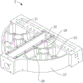
Referring to fig. 10 and 13, in order to further improve the quality of the roll bending process, the roll bending machine further includes a support device 20 for preventing distortion, and the support device 20 for preventing distortion is disposed on the side of the fixed base 2 opposite to the roll bending shaft 81 and between the two axles 3. The support device 20 for preventing distortion comprises a base 201, a sliding support 202, a rotating shaft 203, a support wheel 204 and a position adjusting assembly 205, wherein the base 201 is fixed on the fixing seat 2, the sliding support 202 is slidably disposed on the base 201, the rotating shaft 203 is vertically disposed on the sliding support 202, the support wheel 204 is rotatably mounted on the rotating shaft 203, and the position adjusting assembly 205 is used for adjusting the sliding support 202 to move on the base 201, so that the support wheel 204 and the roll bending wheel 82 respectively abut against two sides of the section bar to be bent. Therefore, the bending quality of the product can be ensured by avoiding the torsion deformation of the section to be bent in the roll bending process.
In order to adjust the height of the supporting wheel 204, a supporting nut 206 is screwed on the rotating shaft 203 below the supporting wheel 204, the supporting wheel 204 is supported on the supporting nut 206, and the supporting wheel 204 is driven to lift by rotating the supporting nut 206. In order to limit the axial sliding of the support wheel 204 along the rotating shaft 203, a limit sleeve 207 and a limit nut 208 are arranged on the rotating shaft 203 above the support wheel 204, and the limit nut 208 is screwed on the rotating shaft 203 at the top end of the limit sleeve 207.
The sliding support 202 includes a sliding bottom plate 2021, an upright plate 2022 and a top end block 2023, the bottom surface of the sliding bottom plate 2021 has a guide portion protruding downward, a guide groove 2011 sliding-fitted with the guide portion is formed on the base 201, the sliding bottom plate 2021 is slidably disposed in the guide groove 2011 of the base 201 through the guide portion, the upright plate 2022 is erected on the sliding bottom plate 2021, the top end block 2023 is disposed parallel to the sliding bottom plate 2021, one end of the top end block 2023 is fixed at the top end of the upright plate 2022, a space for installing the rotating shaft 203 is formed between the other end of the top end block 2023 and the sliding bottom plate 2021, and two ends of the rotating shaft 203 are respectively rotatably mounted on the top end block 2023 and the.
The roll bending machine performs roll bending with different radii by using the principle of three-point circle, and the technical principle thereof is well known to those skilled in the art and is only briefly described here. When a plate or a section is subjected to roll bending processing by using a roll bending machine, the first motor 42 drives the die wheel 30 to rotate through the wheel shaft 3, the second motor 86 drives the roll bending wheel 82 to rotate through the roll bending shaft 81, a workpiece to be roll bent is fed from the die wheel 30 at one side and sequentially passes through the die wheel 30 at one side, the roll bending wheel 82 and the die wheel 30 at the other side, one side of the workpiece to be roll bent is abutted against the two die wheels 30, the other side of the workpiece to be roll bent is abutted against the roll bending wheel 82, the roll bending wheel 82 is equivalent to one tangent point in a circle, the two die wheels 30 are equivalent to two tangent points outside the circle according to a three-point circle principle, and the workpiece to be roll bent is bent and formed under the roll bending wheel 82 and the roll bending action of the two die wheels 30. Due to the rotation of the die wheel 30 and the roll bending wheel 82, and the pressure and friction force generated by the die wheel 30 and the roll bending wheel 82 and the two sides of the workpiece to be roll bent respectively, the workpiece to be roll bent is driven to move and automatically fed for continuous rolling, so that the workpiece to be roll bent is formed into a required bent shape.
The embodiments in the above embodiments can be further combined or replaced, and the embodiments are only described in the preferred embodiments of the present invention, which are not limited to the concept and scope of the present invention, and various changes and modifications made by the technical solutions of the present invention by those skilled in the art without departing from the design concept of the present invention all belong to the protection scope of the present invention.
Claims (9)
1. The utility model provides a strutting arrangement who prevents distortion, characterized in that, including base (201), sliding support (202), pivot (203), supporting wheel (204) and position control subassembly (205), sliding support (202) slide to set up on base (201), pivot (203) rotationally stand and locate on sliding support (202), supporting wheel (204) are rotatable to be located on pivot (203), position control subassembly (205) set up on base (201) and are connected with sliding support (202) for adjust the position of sliding support (202) on base (201).
2. The support device for preventing the distortion of the patent claim 1, wherein the support nut (206) is screwed on the rotating shaft (203) below the support wheel (204), the support wheel (204) is carried on the support nut (206), and the support wheel (204) is driven to lift on the rotating shaft (203) by rotating the support nut (206).
3. The support device for preventing the distortion of the claim 2 is characterized in that a limit nut (208) is arranged on the rotating shaft (203) above the support wheel (204), and the support wheel (204) is clamped and fixed between the support nut (206) and the limit nut (208).
4. The support device for preventing distortion according to claim 3, wherein a limiting sleeve (207) is arranged on the rotating shaft (203) above the support wheel (204), a limiting nut (208) is screwed on the rotating shaft (203) and is located at the top end of the limiting sleeve (207), and the support wheel (204) is clamped and fixed between the support nut (206) and the limiting sleeve (207) and is limited by the top end of the limiting nut (208).
5. The support device for preventing the distortion according to claim 1, wherein the sliding support (202) comprises a sliding bottom plate (2021), a guide portion protruding downwards is arranged on the bottom surface of the sliding bottom plate (2021), a guide groove (2011) matched with the guide portion in a sliding manner is formed on the base (201), and the sliding bottom plate (2021) is arranged in the guide groove (2011) of the base (201) in a sliding manner through the guide portion.
6. The support device for preventing the twisting deformation according to claim 5, wherein the sliding bracket (202) comprises a vertical plate (2022) and a top end block (2023), the vertical plate (2022) is erected on the sliding bottom plate (2021), one end of the top end block (2023) is vertically and fixedly connected to the top end of the vertical plate (2022), a space for installing the rotating shaft (203) is formed between the top end block (2023) and the sliding bottom plate (2021), and two ends of the rotating shaft (203) are rotatably installed on the top end block (2023) and the sliding bottom plate (2021), respectively.
7. The support device for preventing the distortion of claim 6, wherein the position adjusting assembly (205) comprises an adjusting seat (2051) and a screw rod (2052), the adjusting seat (2051) is fixed on the base (201), the adjusting seat (2051) is provided with a threaded hole, the screw rod (2052) is screwed in the threaded hole of the adjusting seat (2051), and one end of the screw rod (2052) is rotatably connected to the vertical plate (2022) of the sliding support (202).
8. A roll bending machine comprises a fixed seat (2), and two wheel shafts (3) and roll bending shafts (81) which are arranged on the fixed seat (2) and are in isosceles triangle arrangement, and is characterized in that the anti-twisting deformation supporting device as claimed in any one of claims 1 to 7 is fixed on one side of the fixed seat (2) opposite to the roll bending shafts (81), the base (201) is fixed on the fixed seat (2), and the roll bending shafts (81) are fixed with roll bending wheels (82) so that the supporting wheels (204) and the roll bending wheels (82) can be respectively and rotatably abutted against two sides of a workpiece.
9. The roll bending machine according to claim 8, wherein the fixed seat (2) is provided with a sliding groove (21) and a guide groove (22) vertically connected with the sliding groove (21), the sliding groove (21) is internally and oppositely provided with a wheel axle seat (4), the wheel axle seat (4) is provided with a wheel axle (3), the guide groove (22) is internally provided with a slide guiding body (83), and the slide guiding body (83) is provided with a roll bending shaft (81).
Priority Applications (1)
| Application Number | Priority Date | Filing Date | Title |
|---|---|---|---|
| CN202020656857.XU CN212042142U (en) | 2020-04-26 | 2020-04-26 | Support device for preventing distortion and roll bending machine |
Applications Claiming Priority (1)
| Application Number | Priority Date | Filing Date | Title |
|---|---|---|---|
| CN202020656857.XU CN212042142U (en) | 2020-04-26 | 2020-04-26 | Support device for preventing distortion and roll bending machine |
Publications (1)
| Publication Number | Publication Date |
|---|---|
| CN212042142U true CN212042142U (en) | 2020-12-01 |
Family
ID=73517676
Family Applications (1)
| Application Number | Title | Priority Date | Filing Date |
|---|---|---|---|
| CN202020656857.XU Active CN212042142U (en) | 2020-04-26 | 2020-04-26 | Support device for preventing distortion and roll bending machine |
Country Status (1)
| Country | Link |
|---|---|
| CN (1) | CN212042142U (en) |
Cited By (2)
| Publication number | Priority date | Publication date | Assignee | Title |
|---|---|---|---|---|
| CN114871311A (en) * | 2022-06-17 | 2022-08-09 | 张家港市格雷斯机械有限公司 | U-shaped pipe stamping device |
| CN115430746A (en) * | 2022-11-09 | 2022-12-06 | 四川富士电机有限公司 | Windscreen wiper arm band iron forming device |
-
2020
- 2020-04-26 CN CN202020656857.XU patent/CN212042142U/en active Active
Cited By (3)
| Publication number | Priority date | Publication date | Assignee | Title |
|---|---|---|---|---|
| CN114871311A (en) * | 2022-06-17 | 2022-08-09 | 张家港市格雷斯机械有限公司 | U-shaped pipe stamping device |
| CN114871311B (en) * | 2022-06-17 | 2023-09-05 | 张家港市格雷斯机械有限公司 | U-shaped pipe stamping device |
| CN115430746A (en) * | 2022-11-09 | 2022-12-06 | 四川富士电机有限公司 | Windscreen wiper arm band iron forming device |
Similar Documents
| Publication | Publication Date | Title |
|---|---|---|
| CN212042142U (en) | Support device for preventing distortion and roll bending machine | |
| CN104985030B (en) | A kind of hydrolic plate bender | |
| CN111360113A (en) | Support device for preventing distortion and roll bending machine | |
| CN109202356A (en) | H profile steel overturns centering body | |
| CN212042139U (en) | Roll bending machine for improving running stability of shaft body | |
| CN212042126U (en) | Roll bending machine convenient to adjust wheel base between mould wheels | |
| CN107745020B (en) | Hydraulic system of four-roller corrugated plate bending machine | |
| CN111421031A (en) | Roll bending machine capable of preventing axial movement of shaft body | |
| CN212042141U (en) | Roll bending machine frame | |
| CN212042140U (en) | Roll bending machine for improving installation stability of motor | |
| CN212285435U (en) | Roll bending machine capable of preventing axial movement of shaft body | |
| CN212042144U (en) | Improved roll bending machine | |
| CN212285436U (en) | Roll bender and fixing base thereof | |
| CN212042143U (en) | Roll bending machine capable of improving machining precision | |
| CN1047335C (en) | Roller type straightening machine | |
| CN212285434U (en) | Roll bending machine convenient to locking wheel axle seat | |
| CN214879874U (en) | Scissors type cross lifting device of engraving machine | |
| CN217223352U (en) | Novel power plant is mould combination for machine-building device | |
| CN216937800U (en) | Novel I-steel straightener | |
| CN213646433U (en) | Clamping and positioning mechanism for traffic sign pole | |
| CN112355981A (en) | Multifunctional mold blank reversing corner machining positioning device | |
| CN111922814A (en) | Processing device for elevator car guide rail production | |
| CN216324663U (en) | Auxiliary supporting device of bending machine | |
| CN220739163U (en) | Device for remanufacturing bolt by using round steel made of sucker rod | |
| CN219093224U (en) | Bending machine convenient to disassemble and maintain |
Legal Events
| Date | Code | Title | Description |
|---|---|---|---|
| GR01 | Patent grant | ||
| GR01 | Patent grant | ||
| CP02 | Change in the address of a patent holder |
Address after: 820 Tian'an Technology Development Building, No. 555 North Panyu Avenue, Donghuan Street, Panyu District, Guangzhou City, Guangdong Province, 511400 Patentee after: GUANGZHOU G CLEF MECHANICAL TECHNOLOGY Co.,Ltd. Address before: 511442 102, North District, No.13, Daban Industrial Zone, tinggen village, Shatou street, Guangzhou City, Guangdong Province Patentee before: GUANGZHOU G CLEF MECHANICAL TECHNOLOGY Co.,Ltd. |
|
| CP02 | Change in the address of a patent holder |