Agitating unit for construction
Technical Field
The invention relates to the field of buildings, in particular to a stirring device for building construction.
Background
In the building construction process, a large amount of concrete is used, the concrete is a general name of engineering composite materials formed by cementing aggregate into a whole by using cementing materials, and the term of the concrete generally refers to that cement is used as the cementing materials, and sand and stone are used as the aggregate; the cement concrete which is mixed with water (which can contain an additive and an admixture) according to a certain proportion and is obtained by stirring is also called as common concrete and is widely applied to construction engineering, the stirring and mixing of the concrete are generally completed by using concrete stirring equipment, but the existing concrete stirring equipment generally only mixes various materials together and simply stirs the materials, so that the problems of uneven stirring and incomplete stirring exist, meanwhile, the existing concrete stirring equipment can not screen and crush gravels with different hardness, and the gravels are carelessly mixed into the cement soil, so that the quality of the concrete is influenced, the labor intensity of workers is increased by independent crushing, and the using requirements of buildings can not be met.
Disclosure of Invention
In order to solve the problems, the invention provides a stirring device for building construction.
The invention is realized by the following technical scheme:
a stirring device for building construction comprises a stirring barrel, wherein a feeding funnel is fixedly communicated with the side wall of the stirring barrel, a first funnel is fixedly communicated with the bottom end of the stirring barrel, the bottom end of the first funnel is in threaded connection with a cover body, a plurality of supporting legs are fixedly and symmetrically connected with the bottom end of the first funnel, two vertical rods are symmetrically and fixedly connected with the inner wall of the first funnel, a conical block is fixedly connected with the top end of the two vertical rods, a vertical pipe is arranged right above the conical block, the top end of the vertical pipe penetrates through the stirring barrel and is fixedly sleeved with a first gear, two limiting rings are fixedly sleeved on the vertical pipe and are positioned at two sides of the stirring barrel and are attached to the surface of the stirring barrel, the vertical pipe is rotatably connected with the stirring barrel, a three-phase asynchronous motor is fixedly connected with a controller through a circuit, and the output end of the three, the second gear is meshed with the first gear, the vertical pipe is symmetrically and fixedly connected with a plurality of stirring rods from bottom to top, the stirring rods are obliquely arranged and arranged in the stirring barrel, the bottom end of the vertical pipe side wall is symmetrically and fixedly connected with two first L-shaped rods, the vertical rod of the first L-shaped rod extends into the first hopper, the bottom end of the conical block is fixedly connected with a second L-shaped rod, the vertical rod of the second L-shaped rod penetrates into the vertical pipe and is attached to the inner side wall of the vertical pipe, the top surface of the stirring barrel is symmetrically and fixedly connected with a plurality of supporting rods, the top ends of the supporting rods are fixedly connected with a second hopper, the bottom end of the second hopper is inserted into the vertical pipe and is rotatably connected with the vertical pipe, the top end of the second hopper is fixedly communicated with a crushing barrel, the side wall of the crushing barrel is hinged with a barrel door through a hinge, the top end of the crushing barrel is, the two filter screens are fixedly connected and inclined downwards, a plurality of transverse plates are symmetrically and fixedly connected to the inner side wall of the crushing barrel, slide rods are arranged at the bottom ends of the transverse plates, limit blocks are fixedly connected to the bottom ends of the slide rods, the top ends of the slide rods penetrate through the transverse plates and are fixedly connected with the bottom surfaces of the filter screens, the slide rods are connected with the transverse plates in a sliding mode, the cross sections of the slide rods are square, first springs are sleeved on the slide rods, the bottom ends of the first springs are attached to the top surfaces of the transverse plates, the first springs are compression springs, third L-shaped rods are fixedly connected to the top ends of the side walls of the crushing barrel, motors are fixedly connected to the bottom ends of the vertical rods of the third L-shaped rods, the motors are electrically connected with controllers through circuits, cams are fixedly sleeved at the output ends of the motors, the cams are oval in shape, balancing weights, the fourth L-shaped rod cross rod penetrates through the first through groove to penetrate through the top surface of the crushing barrel and is fixedly connected with a vertical rod, the top end of the vertical rod is fixedly connected with a lug, the lug is arranged under the cam, the fourth L-shaped rod cross rod is fixedly sleeved with a baffle, the baffle is arranged on one side of the first through groove, the side wall of the crushing barrel is fixedly communicated with an inclined tube, a valve is fixedly connected onto the inclined tube, two third gears are symmetrically attached to the side wall of the crushing barrel and are meshed with each other, a first rotating shaft is fixedly connected to the center of the third gears and penetrates through the crushing barrel and is fixedly connected with a second rotating shaft, the first rotating shaft is rotatably connected with the crushing barrel, the section of the second rotating shaft is square, the output end of the motor is fixedly connected with the side wall of the center of the third gears, the first rotating shaft is rotatably connected with the crushing barrel, and two crushing rollers are, the utility model discloses a novel roller crusher, including crushing roller, barrel door lateral wall, first rotary shaft, second rotary shaft, first dovetail, second dovetail both sides, the laminating slip cover has a plurality of barrels on the second rotary shaft, the barrel cross-section is square, the barrel sets up at the second and leads to the inslot, barrel both sides wall symmetry fixedly connected with second spring, the symmetry has two dovetails to open the crushing roller lateral wall, and two dovetails are located second dovetail both sides and communicate with each other rather than second dovetail both sides, the laminating slip is equipped with a plurality of dovetail blocks in the dovetail, the second spring other end and dovetail block lateral wall fixed connection, open dovetail block one side has the blind hole, another fixedly connected with of dovetail block and the inserted bar that the blind hole suited.
Preferably, the inserted rod adopts Fe3O4And (5) manufacturing materials.
Preferably, the first rotating shaft and the second rotating shaft are connected by welding.
Preferably, the model of the three-phase asynchronous motor is Y2-80M2-4S 150.
Compared with the prior art, the invention has the beneficial effects that: the device has various functions and strong practicability, can realize the full stirring of concrete by arranging the first hopper, the vertical rod, the conical block, the vertical pipe, the first gear, the limiting ring, the three-phase asynchronous motor, the second gear, the stirring rod, the first L-shaped rod and the second L-shaped rod so as to ensure the uniform mixing and improve the quality of finished products, and set up the filter screen, the diaphragm, the stopper, first spring, third L shape pole, including a motor, an end cap, a controller, and a cover plate, the cam, the balancing weight, fourth L shape pole, the montant, the lug, the baffle, the pipe chute, the valve, the third gear, the slide bar, first rotation axis, the second rotation axis, the crushing roller, it is protruding, the barrel, the second spring, dovetail block and inserted bar can realize carrying out the utilization ratio that smashes the screening and improve the stone to the stone of different hardness according to different demands, thereby indirectly improve the quality of concrete, reduce intensity of labour, satisfy the building user demand.
Drawings
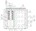
FIG. 1 is a block diagram of the structure of the present invention;
FIG. 2 is a partial left side view of the structure of the present invention;
FIG. 3 is a partial top view of the structure of the present invention;
fig. 4 is a partial enlarged view of the structure of the present invention.
In the figure: a mixing tank 1, a feeding hopper 2, a first hopper 3, a vertical rod 4, a conical block 5, a vertical pipe 6, a first gear 7, a limit ring 8, a three-phase asynchronous motor 9, a second gear 10, a mixing rod 11, a first L-shaped rod 12, a second L-shaped rod 13, a support rod 14, a second hopper 15, a crushing tank 16, a tank door 17, a feeding pipe 18, a filter screen 19, a transverse plate 20, a limit block 21, a first spring 22 and a third L-shaped rod 23, the device comprises a motor 24, a cam 25, a balancing weight 26, a fourth L-shaped rod 27, a vertical rod 28, a bump 29, a baffle 30, an inclined tube 31, a valve 32, a third gear 33, a sliding rod 34, a first rotating shaft 35, a second rotating shaft 36, a crushing roller 37, a bulge 38, a cylinder 39, a second spring 40, a dovetail block 41, an insertion rod 42, a first through groove 16-1, a second through groove 37-1, a dovetail groove 37-2 and a blind hole 41-1.
Detailed Description
The invention is described in further detail below with reference to the following detailed description and accompanying drawings:
as shown in fig. 1, 2, 3 and 4, the stirring device for building construction comprises a stirring barrel 1, wherein a feeding funnel 2 is fixedly communicated with the side wall of the stirring barrel 1, a first funnel 3 is fixedly communicated with the bottom end of the stirring barrel 1, the bottom end of the first funnel 3 is in threaded connection with a cover body, a plurality of support legs are fixedly and symmetrically connected with the bottom end of the first funnel 3, two vertical rods 4 are symmetrically and fixedly connected with the inner wall of the first funnel 3, conical blocks 5 are fixedly connected with the top ends of the two vertical rods 4, a vertical pipe 6 is arranged right above the conical blocks 5, the top end of the vertical pipe 6 penetrates through the stirring barrel 1 and is fixedly sleeved with a first gear 7, two limit rings 8 are fixedly sleeved on the vertical pipe 6, the two limit rings 8 are positioned at two sides of the stirring barrel 1 and are attached to the surface of the stirring barrel, the vertical pipe 6 is rotatably connected with the stirring barrel 1, a, the three-phase asynchronous motor 9 is electrically connected with a controller through a circuit, the output end of the three-phase asynchronous motor 9 is fixedly connected with a second gear 10, the second gear 10 is meshed with a first gear 7, the vertical pipe 6 is symmetrically and fixedly connected with a plurality of stirring rods 11 from bottom to top, the stirring rods 11 are obliquely arranged and arranged in the stirring barrel 1, the bottom end of the side wall of the vertical pipe 6 is symmetrically and fixedly connected with two first L-shaped rods 12, the vertical rod of the first L-shaped rod 12 extends into the first hopper 3, the bottom end of the conical block 5 is fixedly connected with a second L-shaped rod 13, the vertical rod of the second L-shaped rod 13 penetrates into the vertical pipe 6 and is attached to the inner side wall of the vertical pipe, the top surface of the stirring barrel 1 is symmetrically and fixedly connected with a plurality of supporting rods 14, the top ends of the plurality of supporting rods 14 are fixedly connected with a second hopper 15, the bottom end of the second, the top end of the second hopper 15 is fixedly communicated with a crushing barrel 16, the side wall of the crushing barrel 16 is hinged with a barrel door 17 through hinges, the top end of the crushing barrel 16 is fixedly communicated with an inlet pipe 18, two filter screens 19 are symmetrically arranged on the inner side wall of the crushing barrel 16 in an attaching mode, the two filter screens 19 are fixedly connected and incline downwards, a plurality of transverse plates 20 are symmetrically and fixedly connected with the inner side wall of the crushing barrel 16, slide rods 34 are arranged at the bottom ends of the transverse plates 20, limit blocks 21 are fixedly connected with the bottom ends of the slide rods 34, the top ends of the slide rods 34 penetrate through the transverse plates 20 and are fixedly connected with the bottom surfaces of the filter screens 19, the slide rods 34 are slidably connected with the transverse plates 20, the cross sections of the slide rods 34 are square, first springs 22 are sleeved on the slide rods 34, the bottom ends of the first springs 22 are attached to the top surfaces, the bottom ends of the vertical rods of the third L-shaped rods 23 are fixedly connected with a motor 24, the motor 24 is electrically connected with a controller through a circuit, the output end of the motor 24 is fixedly sleeved with a cam 25, the shape of the cam 25 is oval, the side wall of the cam 25 is hinged with a balancing weight 26 through a pin, the side wall of the crushing barrel 16 is provided with a first through groove 16-1, the bottom ends of the two filter screens 19 are fixedly connected with a fourth L-shaped rod 27, the cross rod of the fourth L-shaped rod 27 passes through the first through groove 16-1 and passes through the top surface of the crushing barrel 16 to be fixedly connected with a vertical rod 28, the top end of the vertical rod 28 is fixedly connected with a convex block 29, the convex block 29 is arranged under the cam 25, the cross rod of the fourth L-shaped rod 27 is fixedly sleeved with a baffle 30, the baffle 30 is arranged on one side of the first through groove 16-1, the side wall of the crushing barrel 16 is symmetrically provided with two third gears 33 in an attaching manner, the two third gears 33 are engaged, the center of the third gear 33 is fixedly connected with a first rotating shaft 35, the first rotating shaft 35 penetrates through the crushing barrel 16 and is fixedly connected with a second rotating shaft 36, the first rotating shaft 35 is rotationally connected with the crushing barrel 16, the section of the second rotating shaft 36 is square, the output end of the motor 24 is fixedly connected with the central side wall of the third gear 33, the first rotating shaft 35 is rotationally connected with the crushing barrel 16, the crushing barrel 16 is internally and symmetrically provided with two crushing rollers 37, the surfaces of the crushing rollers 37 are fixedly connected with a plurality of bulges 38, the side wall of each crushing roller 37 is provided with a second through groove 37-1, the second rotating shaft 36 penetrates through the second through groove 37-1 to be attached to the side wall of the barrel door 17, and the second rotating shaft 36 is provided with a plurality of barrel bodies 39 in, the cross section of the cylinder body 39 is square, the cylinder body 39 is arranged in the second through groove 37-1, the two side walls of the cylinder body 39 are symmetrically and fixedly connected with a second spring 40, the side wall of the crushing roller 37 is symmetrically provided with two dovetail grooves 37-2, the two dovetail grooves 37-2 are positioned at the two sides of the second through groove 37-1 and communicated with the second through groove, a plurality of dovetail blocks 41 are arranged in the dovetail grooves 37-2 in a fitting and sliding mode, the other end of the second spring 40 is fixedly connected with the side wall of the dovetail block 41, one side of the dovetail block 41 is provided with a blind hole 41-1, and the other side of the dovetail block 41 is fixedly connected with an inserting rod 42 matched with the blind hole 41-1.
The inserted rod 42 adopts Fe3O4And (5) manufacturing materials.
The first rotating shaft 35 and the second rotating shaft 36 are connected by welding.
The model number of the three-phase asynchronous motor 9 is Y2-80M2-4S 150.
The working principle is as follows: when concrete needs to be manufactured in a building, the device is connected with a power supply, the controller is operated to enable the three-phase asynchronous motor 9 and the motor 24 to start working, the quality of the concrete is closely related to the hardness of the added stones, the stones with corresponding hardness are selected according to the requirement of the quality of the concrete, then the barrel door 17 is opened, the barrel 39 is removed or added, the side wall of the barrel 39 is symmetrically connected with a second spring 40, the other end of the second spring 40 is fixedly connected with a dovetail block 41, the dovetail block 41 is inserted into a dovetail groove 37-2, an inserting rod 42 on the side wall of the dovetail block 41 is correspondingly inserted into a blind hole 41-1, the number of the second spring 40 is changed, the elastic force of the second spring 40 is changed, the stones with corresponding hardness are crushed, the barrel door 17 is closed, then raw materials are added into the crushing barrel 16 from the feeding pipe 18, the raw materials flow into the vertical pipe 6 along the second 15 through the filter screen 19, finally, the crushed stones flow into the conical block 5 and enter the first hopper 3 at the bottom end of the stirring barrel 1, the output end of the motor 24 drives a third gear 33 to rotate, the third gear 33 drives another third gear 33 to rotate, the third gear 33 drives the first rotating shaft 35 to rotate, the first rotating shaft 35 drives the second rotating shaft 36 to rotate, the second rotating shaft 36 drives the barrel 39 to rotate, the crushing roller 37 is driven to rotate, the crushing roller 37 drives the protrusion 38 to rotate to crush the stones, the crushed stones fall onto the filter screen 19, the crushed stones are filtered by the filter screen 19 to flow into the second hopper 15 and then flow into the stirring barrel 1 through the standpipe 6, the larger and harder stones squeeze the crushing roller 37, so that the two crushing rollers 37 move towards each other, then the larger stones fall onto the filter screen 19, the motor 24 drives the cam 25 to rotate, the cam 25 rotates to repeatedly beat the lug 29, so that the lug 29 moves downwards, the bump 29 drives the vertical rod 28 to move, the vertical rod 28 drives the fourth L-shaped rod 27 to move, the fourth L-shaped rod 27 drives the filter screen 19 to move downwards, the filter screen 19 moves downwards to extrude the first spring 22, after the cam 25 is separated from the bump 29, the filter screen 19 is pushed to move upwards by the extruded first spring 22, the filter screen 19 drives the fourth L-shaped rod 27 to move upwards, the fourth L-shaped rod 27 indirectly drives the bump 29 to move upwards, so that the vibration amplitude motion of the filter screen 19 bounces the stones on the surface of the filter screen to be crushed again, the crushed materials enter the stirring barrel 1, then an appropriate amount of water enters the stirring barrel 2 from the feeding hopper to be mixed, the output end of the three-phase asynchronous motor 9 drives the second gear 10 to rotate, the second gear 10 drives the first gear 7 to rotate, the first gear 7 drives the vertical pipe 6 to rotate, the vertical pipe 6 drives the stirring rod 11 to rotate, and the vertical pipe 6 drives the first L, thereby realize the intensive mixing of raw materials, the misce bene, improve the quality of concrete, the standpipe 6 rotates, the second L-shaped pole 13 montant lateral wall is laminated with the standpipe 6 inside wall, prevent the standpipe 6 inner wall from blockking up, realize normal unloading, the stone of great hardness can't be smashed, fall on the filter screen 19, when needing to use the concrete in the agitator 1, open the first funnel 3 bottom lid, discharge the concrete in the agitator 1, the setting of montant 4 and toper piece 5 reduces the impact force of raw materials and agitator 1 and first funnel 3 inner wall, improve the life cycle of the device, the setting of spacing ring 8 has the spacing effect for standpipe 6, guarantee the normal rotation of standpipe 6, the setting of baffle 30 effectively prevents the raw materials from flowing out from the first through groove 16-1 and causing the waste, improve the utilization ratio of raw materials, when needing to discharge the stone on the filter screen 19 surface, open valve 32, great stone is discharged from pipe chute 31, places the receiving device in pipe chute 31 bottom, receives discharged stone, and the amplitude motion of filter screen 19 is convenient for its surperficial stone to discharge, and the crushing of raw materials mixes integrated into one piece, reduces intensity of labour, and after the concrete mixing finishes, operation controller makes three-phase asynchronous motor 9 and motor 24 stop work, then with this device and power separation.
The foregoing illustrates and describes the principles, general features, and advantages of the present invention. It will be understood by those skilled in the art that the present invention is not limited to the embodiments described above, which are described in the specification and illustrated only to illustrate the principle of the present invention, but that various changes and modifications may be made therein without departing from the spirit and scope of the present invention, which fall within the scope of the invention as claimed. The scope of the invention is defined by the appended claims and equivalents thereof.