CN212011663U - Power distribution cabinet convenient to overhaul - Google Patents
Power distribution cabinet convenient to overhaul Download PDFInfo
- Publication number
- CN212011663U CN212011663U CN202020580178.9U CN202020580178U CN212011663U CN 212011663 U CN212011663 U CN 212011663U CN 202020580178 U CN202020580178 U CN 202020580178U CN 212011663 U CN212011663 U CN 212011663U
- Authority
- CN
- China
- Prior art keywords
- fixedly connected
- groove
- distribution cabinet
- power distribution
- sliding
- Prior art date
- Legal status (The legal status is an assumption and is not a legal conclusion. Google has not performed a legal analysis and makes no representation as to the accuracy of the status listed.)
- Expired - Fee Related
Links
Images



Landscapes
- Patch Boards (AREA)
Abstract
The utility model discloses a convenient switch board of overhauing relates to switch board technical field, which comprises a body, the bottom fixedly connected with bottom plate of body, the top fixedly connected with roof of body, one side of body articulates there is the apron, one side fixedly connected with hand (hold) of apron, first spacing groove and second spacing groove have been seted up on the surface of hand (hold), the inside swing joint of second spacing groove has the inserted bar, the inserted bar is close to the one end fixedly connected with sloping block of body, the apron has been close to one side of hand (hold) and has been seted up bar hole and through-hole, the inside swing joint of first spacing groove has the horizontal pole. This switch board that conveniently overhauls through using buckle structure, makes the cabinet door simple and convenient that opens and shuts, reduces the time of opening the cabinet door, has improved work efficiency, through using detachable construction, makes the both sides of switch board also can open, and the inner space of switch board when increasing the maintenance makes the staff conveniently operate, has improved maintenance efficiency.
Description
Technical Field
The utility model relates to a switch board technical field specifically is a switch board of convenient maintenance.
Background
The distribution cabinet is a final-stage device of a distribution system. The power distribution cabinet is a general name of a motor control center. The distribution cabinet is used in the occasions with dispersed loads and less loops, the motor control center is used in the occasions with concentrated loads and more loops, and the distribution cabinet distributes the electric energy of a certain circuit of the upper-level distribution equipment to the nearby loads. This level of equipment should provide protection, monitoring and control of the load. The space of the existing power distribution cabinet is narrow, and the opening and closing of the cabinet door is troublesome and time-consuming and labor-consuming.
In chinese utility model patent application no: CN201610955865.2 discloses an electric switch board convenient to overhaul, the device is including electric switch board, slide rail, slider, spring, first leading wheel, first wire rope, second leading wheel, movable plate, mounting panel, bolt, LED lamp etc. and the top is connected with the slide rail through bolted connection's mode in the electric switch board, and sliding connection has the slider on the slide rail, is connected with the spring through the mode of being connected of couple between slider left side and the slide rail, and the welding of slide rail right side has first leading wheel. The device uses lighting device to make it reach the purpose of being convenient for maintain in the use, but lighting device is more occupation space, and the space is narrow in the switch board in addition, makes the maintenance more troublesome.
Therefore, it is necessary to provide a power distribution cabinet convenient for maintenance to solve the above problems.
SUMMERY OF THE UTILITY MODEL
Technical problem to be solved
An object of the utility model is to provide a switch board of convenient maintenance to the current switch board that proposes among the solution above-mentioned background art opens and shuts the problem that the cabinet door is more troublesome and inconvenient maintenance.
(II) technical scheme
In order to achieve the above purpose, the utility model discloses a following technical scheme realizes: a power distribution cabinet convenient to overhaul comprises a body, wherein a bottom plate is fixedly connected to the bottom of the body, a top plate is fixedly connected to the top of the body, a cover plate is hinged to one side of the body, a handle is fixedly connected to one side of the cover plate, a first limiting groove and a second limiting groove are formed in the surface of the handle, an inserting rod is movably connected to the inside of the second limiting groove, an inclined block is fixedly connected to one end, close to the body, of the inserting rod, a strip-shaped hole and a through hole are formed in one side, close to the handle, of the cover plate, a cross rod is movably connected to the inside of the first limiting groove, a second spring is sleeved on the outer side of the cross rod, a first clamping groove, a limiting hole and a groove are formed in the surface, close to the handle, of the body, a pressure spring is fixedly connected to one side of the groove, a, the bottom fixedly connected with slider of first spring, one side fixedly connected with push rod of slider, the push rod is kept away from the one end surface of slider and has been seted up the second draw-in groove, the spout has all been seted up to the inside both sides of body, the inside swing joint of spout has the slide, the equal swing joint in both ends of bottom plate has the fly leaf, the rectangular channel has been seted up on the top of fly leaf, the rectangular hole has all been seted up to the both sides bottom of body and fly leaf, the circular recess has been seted up to the inside of body, the inside swing joint of rectangular hole has the connecting axle, coil spring has been cup jointed in the outside of connecting axle, the top fixedly connected with.
Preferably, the sliding groove and the rectangular groove are matched with the sliding plate.
Preferably, the movable block is connected with the bottom of the groove in a sliding mode.
Preferably, the bottom of the sliding block is an inclined plane.
Preferably, the bottom of one end of the cross rod, which is far away from the handle, is matched with the second clamping groove.
Preferably, the groove is communicated with a first clamping groove, and the first clamping groove is communicated with the limiting hole.
Preferably, the push rod penetrates through the limiting hole.
(III) advantageous effects
Compared with the prior art, the utility model provides a convenient switch board of overhauing possesses following beneficial effect:
1. this switch board that conveniently overhauls through using buckle structure, makes the cabinet door simple and convenient that opens and shuts, reduces the time of opening the cabinet door, has improved work efficiency.
2. This switch board that conveniently overhauls through using detachable construction, makes the both sides of switch board also can open, and the inner space of switch board when the increase maintenance makes the staff conveniently operate, has improved maintenance efficiency.
Drawings
FIG. 1 is a schematic view of the structure of the present invention;
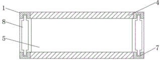
FIG. 2 is a schematic top sectional view of the structure of the present invention;
FIG. 3 is a schematic left-side sectional view of the structure of the present invention;
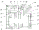
FIG. 4 is an enlarged schematic view of the structure at A in FIG. 3 according to the present invention;
fig. 5 is a schematic cross-sectional view of the buckle structure of the present invention.
In the figure: 1. a body; 2. a handle; 3. a top plate; 4. a cover plate; 5. a base plate; 6. a movable plate; 7. a chute; 8. a slide plate; 9. a rectangular groove; 10. a circular groove; 11. a clamping block; 12. a rectangular hole; 13. a coil spring; 14. a connecting shaft; 15. a groove; 16. a first card slot; 17. a pressure spring; 18. a movable block; 19. a sloping block; 20. inserting a rod; 21. a through hole; 22. a slider; 23. a limiting hole; 24. a push rod; 25. a second card slot; 26. a first spring; 27. a strip-shaped hole; 28. a first limit groove; 29. a second spring; 30. a cross bar; 31. a second limit groove.
Detailed Description
The technical solutions in the embodiments of the present invention will be described clearly and completely with reference to the accompanying drawings in the embodiments of the present invention, and it is obvious that the described embodiments are only some embodiments of the present invention, not all embodiments. Based on the embodiments in the present invention, all other embodiments obtained by a person skilled in the art without creative work belong to the protection scope of the present invention.
Referring to fig. 1-5, a power distribution cabinet convenient for maintenance includes a body 1, a bottom plate 5 fixedly connected to the bottom of the body 1, a top plate 3 fixedly connected to the top of the body 1, a cover plate 4 hinged to one side of the body 1, a handle 2 fixedly connected to one side of the cover plate 4, a first limit groove 28 and a second limit groove 31 formed on the surface of the handle 2, an insertion rod 20 movably connected to the inside of the second limit groove 31, an oblique block 19 fixedly connected to one end of the insertion rod 20 close to the body 1, a bar-shaped hole 27 and a through hole 21 formed on one side of the cover plate 4 close to the handle 2, a cross rod 30 movably connected to the inside of the first limit groove 28, a bottom end of the cross rod 30 far away from the handle 2 and adapted to the second slot 25, the slide block 22 is driven by the cross rod 30 to limit the oblique block 19, a second spring 29 is sleeved on the outer side of the cross rod 30, a first slot, The cabinet door opening and closing device comprises a limiting hole 23 and a groove 15, wherein the groove 15 is communicated with a first clamping groove 16, the first clamping groove 16 is communicated with the limiting hole 23, one side of the groove 15 is fixedly connected with a pressure spring 17, one side of the pressure spring 17 is fixedly connected with a movable block 18, the movable block 18 is in sliding connection with the bottom of the groove 15, the top of the first clamping groove 16 is fixedly connected with a first spring 26, the bottom of the first spring 26 is fixedly connected with a sliding block 22, the bottom of the sliding block 22 is an inclined plane, one side of the sliding block 22 is fixedly connected with a push rod 24, the push rod 24 penetrates through the limiting hole 23, through using a buckle structure, the inclined block 19 is limited through the sliding block 22, so that the cover plate 4 is controlled to be opened and closed simply and conveniently, the cabinet door opening and closing time is shortened, the working efficiency is improved, a second clamping groove 25 is arranged on the surface of the end, away from the, change traditional fixed box structure, when making the staff maintain, the home range of hand is bigger, be favorable to overhauing, the inside swing joint of spout 7 has slide 8, the equal swing joint in both ends of bottom plate 5 has fly leaf 6, rectangular channel 9 has been seted up on the top of fly leaf 6, rectangular hole 12 has all been seted up to the both sides bottom of body 1 and fly leaf 6, circular slot 10 has been seted up to the inside of body 1, the inside swing joint of rectangular hole 12 has connecting axle 14, coil spring 13 has been cup jointed in the outside of connecting axle 14, the top fixedly connected with fixture block 11 of connecting axle 14, through using detachable construction, the both sides that make the switch board also can be opened, the inner space of switch board during increase maintenance, make the staff conveniently operate, the maintenance efficiency is improved.
The working principle is as follows: when the power distribution cabinet is in operation, the cross rod 30 is pressed rightwards to extrude the second spring 29, the cross rod 30 moves rightwards and is meshed with the second clamping groove 25, the cross rod 30 is pushed upwards, the cross rod 30 drives the push rod 24 to move, the slide block 22 moves upwards and compresses the first spring 26, at the moment, the inclined block 19 is not limited by the slide block 22, the inserted rod 20 is ejected out of the groove 15 under the action of the pressure spring 17, the handle 2 is pulled, the cover plate 4 can be opened, when maintenance is carried out, the connecting shaft 14 is pushed upwards, the connecting shaft 14 compresses the spiral spring 13 and moves upwards, the connecting shaft 14 is rotated, the clamping block 11 is combined with the rectangular hole 12, the connecting shaft 14 can be taken down under the action of the spiral spring 13, then the movable plate 6 is taken down, the sliding plate 8 is pulled downwards, the sliding plate 8 can be taken out of the sliding groove 7, at the moment, the inner space of the power, the working efficiency is improved.
It is noted that, herein, relational terms such as first and second, and the like may be used solely to distinguish one entity or action from another entity or action without necessarily requiring or implying any actual such relationship or order between such entities or actions. Also, the terms "comprises," "comprising," or any other variation thereof, are intended to cover a non-exclusive inclusion, such that a process, method, article, or apparatus that comprises a list of elements does not include only those elements but may include other elements not expressly listed or inherent to such process, method, article, or apparatus. Without further limitation, an element defined by the phrase "comprising an … …" does not exclude the presence of other identical elements in a process, method, article, or apparatus that comprises the element.
Although embodiments of the present invention have been shown and described, it will be appreciated by those skilled in the art that changes, modifications, substitutions and alterations can be made in these embodiments without departing from the principles and spirit of the invention, the scope of which is defined in the appended claims and their equivalents.
Claims (7)
1. The utility model provides a switch board of convenient maintenance, includes body (1), its characterized in that: the bottom fixedly connected with bottom plate (5) of body (1), top fixedly connected with roof (3) of body (1), one side of body (1) articulates there is apron (4), one side fixedly connected with hand (2) of apron (4), first spacing groove (28) and second spacing groove (31) have been seted up on the surface of hand (2), the inside swing joint of second spacing groove (31) has inserted bar (20), one end fixedly connected with sloping block (19) that inserted bar (20) are close to body (1), bar hole (27) and through-hole (21) have been seted up to one side that apron (4) are close to hand (2), the inside swing joint of first spacing groove (28) has horizontal pole (30), second spring (29) have been cup jointed in the outside of horizontal pole (30), body (1) is close to one side surface of hand (2) and has been seted up first draw-in groove (16), The clamping device comprises a limiting hole (23) and a groove (15), wherein a pressure spring (17) is fixedly connected to one side of the groove (15), a movable block (18) is fixedly connected to one side of the pressure spring (17), a first spring (26) is fixedly connected to the top of a first clamping groove (16), a sliding block (22) is fixedly connected to the bottom of the first spring (26), a push rod (24) is fixedly connected to one side of the sliding block (22), a second clamping groove (25) is formed in the surface of one end, far away from the sliding block (22), of the push rod (24), sliding grooves (7) are formed in two sides of the interior of a body (1), sliding plates (8) are movably connected to the interior of the sliding grooves (7), movable plates (6) are movably connected to two ends of a bottom plate (5), rectangular grooves (9) are formed in the top ends of the movable plates (6), rectangular holes (12) are formed in the bottoms, circular slot (10) have been seted up to the inside of body (1), the inside swing joint of rectangular hole (12) has connecting axle (14), coil spring (13) have been cup jointed in the outside of connecting axle (14), the top fixedly connected with fixture block (11) of connecting axle (14).
2. The power distribution cabinet convenient to overhaul according to claim 1, wherein: the sliding groove (7) and the rectangular groove (9) are matched with the sliding plate (8).
3. The power distribution cabinet convenient to overhaul according to claim 1, wherein: the movable block (18) is connected with the bottom of the groove (15) in a sliding mode.
4. The power distribution cabinet convenient to overhaul according to claim 1, wherein: the bottom of the sliding block (22) is an inclined plane.
5. The power distribution cabinet convenient to overhaul according to claim 1, wherein: the bottom of one end, far away from the handle (2), of the cross rod (30) is matched with the second clamping groove (25).
6. The power distribution cabinet convenient to overhaul according to claim 1, wherein: the groove (15) is communicated with a first clamping groove (16), and the first clamping groove (16) is communicated with a limiting hole (23).
7. The power distribution cabinet convenient to overhaul according to claim 1, wherein: the push rod (24) penetrates through the limiting hole (23).
Priority Applications (1)
| Application Number | Priority Date | Filing Date | Title |
|---|---|---|---|
| CN202020580178.9U CN212011663U (en) | 2020-04-18 | 2020-04-18 | Power distribution cabinet convenient to overhaul |
Applications Claiming Priority (1)
| Application Number | Priority Date | Filing Date | Title |
|---|---|---|---|
| CN202020580178.9U CN212011663U (en) | 2020-04-18 | 2020-04-18 | Power distribution cabinet convenient to overhaul |
Publications (1)
| Publication Number | Publication Date |
|---|---|
| CN212011663U true CN212011663U (en) | 2020-11-24 |
Family
ID=73416221
Family Applications (1)
| Application Number | Title | Priority Date | Filing Date |
|---|---|---|---|
| CN202020580178.9U Expired - Fee Related CN212011663U (en) | 2020-04-18 | 2020-04-18 | Power distribution cabinet convenient to overhaul |
Country Status (1)
| Country | Link |
|---|---|
| CN (1) | CN212011663U (en) |
Cited By (1)
| Publication number | Priority date | Publication date | Assignee | Title |
|---|---|---|---|---|
| CN113991464A (en) * | 2021-12-03 | 2022-01-28 | 内蒙古民族大学 | Low-voltage dynamic mixed harmonic reactive power compensation device |
-
2020
- 2020-04-18 CN CN202020580178.9U patent/CN212011663U/en not_active Expired - Fee Related
Cited By (2)
| Publication number | Priority date | Publication date | Assignee | Title |
|---|---|---|---|---|
| CN113991464A (en) * | 2021-12-03 | 2022-01-28 | 内蒙古民族大学 | Low-voltage dynamic mixed harmonic reactive power compensation device |
| CN113991464B (en) * | 2021-12-03 | 2023-09-12 | 内蒙古民族大学 | Low-voltage dynamic mixed harmonic reactive compensation device |
Similar Documents
| Publication | Publication Date | Title |
|---|---|---|
| AT413185B (en) | FURNITURE DRAWER | |
| CN216355490U (en) | Power distribution cabinet convenient to maintain | |
| CN213244571U (en) | Wisdom light pole is with electrical apparatus case convenient to dismantle | |
| CN107951208B (en) | An intelligent compact rack | |
| CN213505446U (en) | Combined elevator electric control box | |
| CN214588309U (en) | Box transformer convenient to installation | |
| CN217823774U (en) | Combined low-voltage switch cabinet | |
| CN209929762U (en) | Conveniently-opened household distribution box | |
| CN214960424U (en) | Wisdom is control management equipment for street lamp | |
| CN211822083U (en) | Wisdom street lamp of convenient maintenance | |
| CN212626831U (en) | Novel armor withdrawable type AC metal-enclosed switchgear | |
| CN221353521U (en) | High switch board of security | |
| CN211793374U (en) | Frame is planted with multilayer to domestic fungus | |
| CN211405168U (en) | Block terminal for electronic communication | |
| CN209071919U (en) | A kind of Contiuum type low-voltage distribution cabinet convenient for combination installation | |
| CN209766907U (en) | integral type low-voltage distribution cabinet convenient to installation | |
| CN208895053U (en) | A kind of optoelectronic communication production mould waste material collection device | |
| CN206195226U (en) | A formula interlocking gear casing plate pulls out for electric power rack | |
| CN215579777U (en) | Intelligent power equipment power distribution cabinet | |
| CN214899456U (en) | Power distribution cabinet | |
| CN213333794U (en) | Mobilizable security protection lighting device at night | |
| CN213125293U (en) | Switch cabinet with hoisting mechanism | |
| CN216121354U (en) | Control circuit switch board | |
| CN223206647U (en) | A multifunctional double-door safety electric box | |
| CN219739681U (en) | Small-sized multi-switch ring main unit |
Legal Events
| Date | Code | Title | Description |
|---|---|---|---|
| GR01 | Patent grant | ||
| GR01 | Patent grant | ||
| CF01 | Termination of patent right due to non-payment of annual fee |
Granted publication date: 20201124 Termination date: 20210418 |
|
| CF01 | Termination of patent right due to non-payment of annual fee |