CN211999061U - A biodegradable sewage treatment equipment - Google Patents
A biodegradable sewage treatment equipment Download PDFInfo
- Publication number
- CN211999061U CN211999061U CN202020248022.0U CN202020248022U CN211999061U CN 211999061 U CN211999061 U CN 211999061U CN 202020248022 U CN202020248022 U CN 202020248022U CN 211999061 U CN211999061 U CN 211999061U
- Authority
- CN
- China
- Prior art keywords
- rack
- box
- spacing
- box body
- card
- Prior art date
- Legal status (The legal status is an assumption and is not a legal conclusion. Google has not performed a legal analysis and makes no representation as to the accuracy of the status listed.)
- Active
Links
Images


Landscapes
- Biological Treatment Of Waste Water (AREA)
Abstract
本实用新型公开了一种生物降解式污水处理设备,包括支脚、箱体和固定花板,所述箱体下表面焊接有支脚,所述箱体一侧下端安装有进水管,所述箱体另一侧上端安装有出水管,所述箱体内部上端安装有固定花板,所述固定花板上表面安装有限位卡,且限位卡下端安装有生物架,所述箱体内部下端安装有限位孔板,所述限位孔板和固定花板中间位置处设置有升降花板。本实用新型能够通过生物降解的方式进行污水的处理,处理量大,且处理效果好,能够将有害物质有效的降低,且能够提高降解的效率,如果生物降解方式的污水处理设备能够大量得到应用,能够使环境保护方面做的更好。
The utility model discloses a biodegradable sewage treatment equipment, which comprises a supporting foot, a box body and a fixed pattern plate. The supporting foot is welded on the lower surface of the box body, and a water inlet pipe is installed at the lower end of one side of the box body. A water outlet pipe is installed on the upper end of the other side, a fixed flower plate is installed on the upper end of the inside of the box body, a limit card is installed on the surface of the fixed flower plate, and a biological frame is installed at the lower end of the limit card, and the lower end of the inside of the box body is installed The limit orifice plate is provided with a lifting flower plate at the middle position of the limit orifice plate and the fixed flower plate. The utility model can treat sewage by means of biodegradation, has large treatment capacity and good treatment effect, can effectively reduce harmful substances, and can improve the efficiency of degradation. , can make environmental protection do better.
Description
技术领域technical field
本实用新型涉及生物降解污水处理设备技术领域,具体为一种生物降解式污水处理设备。The utility model relates to the technical field of biodegradable sewage treatment equipment, in particular to a biodegradable sewage treatment equipment.
背景技术Background technique
利用微生物的代谢作用除去废水中有机污染物的一种方法,亦称废水生物化学处理法,简称废水生化法,随着工业的发展,污水成分已愈来愈复杂,某些难降解的有机物质和有毒物质,需要运用微生物的方法进行处理,污水具备微生物生长和繁殖的条件,因而微生物能从污水中获取养分,同时降解和利用有害物质,从而使污水得到净化。A method of removing organic pollutants in wastewater by the metabolism of microorganisms, also known as wastewater biochemical treatment method, referred to as wastewater biochemical method. And toxic substances need to be treated by microbial methods. Sewage has the conditions for microbial growth and reproduction, so microorganisms can obtain nutrients from sewage, and at the same time degrade and utilize harmful substances, so that sewage can be purified.
目前国内外的所有污水处理设备都是通过沉淀的方式,进行去除污水中的杂质,这种处理方式不仅效率低下,且占地面积庞大,且已经不能满足人类的污水处理要求了,所以,现在,需要一种能够更快更好更加小型的污水处理设备,方便进行污水的处理工作。At present, all sewage treatment equipment at home and abroad remove impurities in sewage by means of precipitation. This treatment method is not only inefficient, but also occupies a large area, and can no longer meet the requirements of human sewage treatment. Therefore, now , a faster, better and smaller sewage treatment equipment is needed to facilitate the treatment of sewage.
实用新型内容Utility model content
本实用新型的目的在于提供一种生物降解式污水处理设备,具备能够有效的通过生物降解的方式,将污水进行有效的处理的优点,解决了目前世界上普遍面对的污水处理的问题。The purpose of this utility model is to provide a biodegradable sewage treatment equipment, which has the advantage of being able to effectively treat sewage by means of biodegradation, and solves the problem of sewage treatment commonly faced in the world at present.
为实现上述目的,本实用新型提供如下技术方案:一种生物降解式污水处理设备,包括支脚、箱体和固定花板,所述箱体下表面焊接有支脚,所述箱体一侧下端安装有进水管,所述箱体另一侧上端安装有出水管,所述箱体内部上端安装有固定花板,所述固定花板上表面安装有限位卡,且限位卡下端安装有生物架,所述箱体内部下端安装有限位孔板,所述限位孔板和固定花板中间位置处设置有升降花板。In order to achieve the above purpose, the utility model provides the following technical solutions: a biodegradable sewage treatment equipment, comprising feet, a box body and a fixed pattern plate, the lower surface of the box body is welded with feet, and the lower end of one side of the box body is installed There is a water inlet pipe, a water outlet pipe is installed on the upper end of the other side of the box body, a fixed flower plate is installed on the upper end of the inside of the box body, a limit card is installed on the surface of the fixed flower plate, and a biological frame is installed at the lower end of the limit card , a limit orifice plate is installed at the lower end of the box body, and a lifting flower plate is arranged at the middle position of the limit orifice plate and the fixed flower plate.
优选的,所述支脚共设有四个,且四个支脚分设于箱体下表面四个角的位置处。Preferably, there are four supporting feet in total, and the four supporting feet are respectively arranged at the four corners of the lower surface of the box body.
优选的,所述箱体内部底端安装有锥形导料块,所述锥形导料块中间位置处安装有废料排出管。Preferably, a conical material guide block is installed at the bottom end of the box body, and a waste discharge pipe is installed at the middle position of the conical material guide block.
优选的,所述限位孔板与固定花板相对面通过限位柱连接,且限位柱共设有四个,四个所述限位柱分设于限位孔板和固定花板相对面四个角的位置处,且四个所述限位柱贯穿升降花板,所述升降花板内部安装有清洁毛刷。Preferably, the limit orifice plate and the opposite surface of the fixed flower plate are connected by limit columns, and there are four limit columns in total, and the four limit columns are respectively arranged on the opposite surface of the limit hole plate and the fixed flower plate. At the positions of the four corners, and the four limit posts penetrate through the lifting flower plate, and a cleaning brush is installed inside the lifting flower plate.
优选的,所述箱体顶端一侧安装有驱动电机,且驱动电机输出端安装有齿轮,所述齿轮一侧设置有齿条,且齿轮与齿条相啮合,所述齿条底端安装在升降花板上表面。Preferably, a drive motor is installed on one side of the top end of the box body, and a gear is installed at the output end of the drive motor, a rack is installed on one side of the gear, and the gear is meshed with the rack, and the bottom end of the rack is installed on the The upper surface of the lifting board.
优选的,所述箱体内部顶端与齿条相对应的位置处设置有环安装板,且环安装板共设有两个,两个所述环安装板关于齿条对称分布,所述环安装板相对面通过齿条限位环连接,且齿条限位环共设有两个,两个所述齿条限位环套接在齿条外侧。Preferably, a ring mounting plate is provided at a position corresponding to the rack at the inner top of the box, and there are two ring mounting plates in total, and the two ring mounting plates are symmetrically distributed about the rack, and the ring mounting plates The opposite surfaces of the plates are connected by a rack limit ring, and there are two rack limit rings in total, and the two rack limit rings are sleeved on the outside of the rack.
与现有技术相比,本实用新型的有益效果如下:Compared with the prior art, the beneficial effects of the present utility model are as follows:
1、本实用新型通过设置生物架、固定花板和限位卡,达到了方便进行生物架的装卸的效果,通过固定花板和限位卡之间的连接,方便将下方的生物架进行拆除,方便进行更换内部的物质,继而进行后续的处理工作。1. The utility model achieves the effect of facilitating the loading and unloading of the biological frame by arranging the biological frame, the fixed flower plate and the limit card. The connection between the fixed flower plate and the limit card facilitates the removal of the lower biological frame. , it is convenient to replace the internal substances, and then carry out the follow-up processing work.
2、本实用新型通过设置升降花板和驱动电机,达到了方便将沙僧将花板进行升降,从而对生物架外表面进行清洁的效果,当需要进行清洁的时候,通过驱动电机的转动,带动齿轮齿条进行运动,使齿条带动升降花板在限位柱的限位作用下进行移动,通过清洁毛刷将生物架的外表面进行清洁,通过清洁,能够使设备单次的使用时间更长。2. The utility model achieves the effect of facilitating the lifting and lowering of the flower plate by the sand monk by arranging the lifting and lowering flower plate and the driving motor, thereby cleaning the outer surface of the biological frame. When cleaning is required, through the rotation of the driving motor, Drive the rack and pinion to move, so that the rack drives the lifting plate to move under the limit action of the limit column, and the outer surface of the biological frame is cleaned by the cleaning brush. Through cleaning, the equipment can be used for a single time. longer.
附图说明Description of drawings
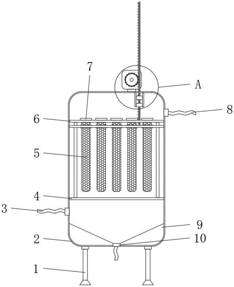
图1为本实用新型的主视结构示意图;Fig. 1 is the front view structure schematic diagram of the utility model;
图2为本实用新型的限位孔板与固定花板局部放大结构示意图;Fig. 2 is a partial enlarged structural schematic diagram of the limiting orifice plate and the fixed flower plate of the present invention;
图3为本实用新型的A处局部放大结构示意图。FIG. 3 is a schematic diagram of a partially enlarged structure of the A part of the present invention.
图中:1、支脚;2、箱体;3、进水管;4、限位孔板;5、生物架;6、固定花板;7、限位卡;8、出水管;9、锥形导料块;10、废料排出管;11、升降花板;12、清洁毛刷;13、限位柱;14、驱动电机;15、齿轮;16、齿条;17、环安装板;18、齿条限位环。In the picture: 1. Support foot; 2. Box body; 3. Water inlet pipe; 4. Limiting orifice plate; 5. Biological frame; 6. Fixed flower plate; 7. Limiting card; 8. Water outlet pipe; 9. Conical Guide block; 10. Waste discharge pipe; 11. Lifting flower plate; 12. Cleaning brush; 13. Limiting column; 14. Driving motor; 15. Gear; 16. Rack; 17. Ring mounting plate; 18. Rack limit ring.
具体实施方式Detailed ways
下面将结合本实用新型实施例中的附图,对本实用新型实施例中的技术方案进行清楚、完整地描述,显然,所描述的实施例仅仅是本实用新型一部分实施例,而不是全部的实施例。基于本实用新型中的实施例,本领域普通技术人员在没有做出创造性劳动前提下所获得的所有其他实施例,都属于本实用新型保护的范围。The technical solutions in the embodiments of the present utility model will be clearly and completely described below with reference to the accompanying drawings in the embodiments of the present utility model. Obviously, the described embodiments are only a part of the embodiments of the present utility model, rather than all the implementations. example. Based on the embodiments of the present invention, all other embodiments obtained by those of ordinary skill in the art without creative work fall within the protection scope of the present invention.
在本实用新型的描述中,需要说明的是,术语“上”、“下”、“内”、“外”“前端”、“后端”、“两端”、“一端”、“另一端”等指示的方位或位置关系为基于附图所示的方位或位置关系,仅是为了便于描述本实用新型和简化描述,而不是指示或暗示所指的装置或元件必须具有特定的方位、以特定的方位构造和操作,因此不能理解为对本实用新型的限制。此外,术语“第一”、“第二”仅用于描述目的,而不能理解为指示或暗示相对重要性。In the description of the present invention, it should be noted that the terms "upper", "lower", "inner", "outer", "front end", "rear end", "two ends", "one end", "the other end" The orientation or positional relationship indicated by "" etc. is based on the orientation or positional relationship shown in the accompanying drawings, and is only for the convenience of describing the present invention and simplifying the description, rather than indicating or implying that the indicated device or element must have a specific orientation, so as to The specific orientation configuration and operation is therefore not to be construed as a limitation of the present invention. Furthermore, the terms "first" and "second" are used for descriptive purposes only and should not be construed to indicate or imply relative importance.
在本实用新型的描述中,需要说明的是,除非另有明确的规定和限定,术语“安装”、“设置有”、“连接”等,应做广义理解,例如“连接”,可以是固定连接,也可以是可拆卸连接,或一体地连接;可以是机械连接,也可以是电连接;可以是直接相连,也可以通过中间媒介间接相连,可以是两个元件内部的连通。对于本领域的普通技术人员而言,可以具体情况理解上述术语在本实用新型中的具体含义。请参阅图1,本实用新型提供的一种实施例:一种生物降解式污水处理设备,包括支脚1、箱体2和固定花板6,箱体2下表面焊接有支脚1,支脚1共设有四个,且四个支脚1分设于箱体2下表面四个角的位置处,箱体2内部底端安装有锥形导料块9,锥形导料块9中间位置处安装有废料排出管10,设备使用一段时间之后,在锥形导料块9的导料作用下,通过废料排出管10将箱体内部囤积的废物进行去除,从而对设备进行清洁工作。箱体2一侧下端安装有进水管3,箱体2另一侧上端安装有出水管8,箱体2内部上端安装有固定花板 6,固定花板6上表面安装有限位卡7,且限位卡7下端安装有生物架5,箱体2内部下端安装有限位孔板4,限位孔板4和固定花板6 中间位置处设置有升降花板11。In the description of the present utility model, it should be noted that, unless otherwise expressly specified and limited, the terms "installed", "provided with", "connected", etc., should be understood in a broad sense, for example, "connected" may be a fixed The connection can also be a detachable connection, or an integral connection; it can be a mechanical connection or an electrical connection; it can be a direct connection, or an indirect connection through an intermediate medium, and it can be internal communication between two components. For those of ordinary skill in the art, the specific meanings of the above terms in the present invention can be understood in specific situations. Please refer to FIG. 1 , an embodiment provided by the present utility model: a biodegradable sewage treatment equipment, including a supporting
请参阅图1和图2,本实用新型提供的一种实施例:一种生物降解式污水处理设备,包括支脚1、箱体2和固定花板6,箱体2下表面焊接有支脚1,箱体2一侧下端安装有进水管3,箱体2另一侧上端安装有出水管8,箱体2内部上端安装有固定花板6,固定花板6上表面安装有限位卡7,且限位卡7下端安装有生物架5,箱体2内部下端安装有限位孔板4,限位孔板4和固定花板6中间位置处设置有升降花板11,限位孔板4与固定花板6相对面通过限位柱13连接,且限位柱13共设有四个,四个限位柱13分设于限位孔板4和固定花板 6相对面四个角的位置处,通过设置限位柱13,能够使升降花板11 在上升和下降的时候,不会发生偏离,方便进行生物架5的清洁工作,且四个限位柱13贯穿升降花板11,升降花板11内部安装有清洁毛刷12,设备使用一段时间之后,通过升降花板11的升降,带动清洁毛刷12进行上下移动,通过清洁毛刷12将生物架5外表面的杂物进行去除。Please refer to FIG. 1 and FIG. 2, an embodiment provided by the present utility model: a biodegradable sewage treatment equipment, comprising a
请参阅图1和图3,本实用新型提供的一种实施例:一种生物降解式污水处理设备,包括支脚1、箱体2和固定花板6,箱体2下表面焊接有支脚1,箱体2一侧下端安装有进水管3,箱体2另一侧上端安装有出水管8,箱体2内部上端安装有固定花板6,固定花板6上表面安装有限位卡7,且限位卡7下端安装有生物架5,箱体2内部下端安装有限位孔板4,限位孔板4和固定花板6中间位置处设置有升降花板11,箱体2顶端一侧安装有驱动电机14,且驱动电机14输出端安装有齿轮15,齿轮15一侧设置有齿条16,且齿轮15与齿条16 相啮合,齿条16底端安装在升降花板11上表面,箱体2内部顶端与齿条16相对应的位置处设置有环安装板17,且环安装板17共设有两个,两个环安装板17关于齿条16对称分布,环安装板17相对面通过齿条限位环18连接,且齿条限位环18共设有两个,所述齿条限位环18能够限制齿条16的升降,使齿条16只能完成竖直方向的升降动作,两个齿条限位环18套接在齿条16外侧。Please refer to FIG. 1 and FIG. 3 , an embodiment provided by the present utility model: a biodegradable sewage treatment equipment, comprising a support leg 1, a box body 2 and a fixed flower plate 6, and a support leg 1 is welded on the lower surface of the box body 2, A water inlet pipe 3 is installed on the lower end of one side of the box body 2, a water outlet pipe 8 is installed on the upper end of the other side of the box body 2, a fixed flower plate 6 is installed on the upper end of the box body 2, and a limit card 7 is installed on the upper surface of the fixed flower plate 6, and A biological frame 5 is installed at the lower end of the limit card 7, a limit hole plate 4 is installed at the lower end of the box body 2, a lifting flower plate 11 is arranged at the middle position of the limit hole plate 4 and the fixed flower plate 6, and the top side of the box body 2 is installed There is a drive motor 14, and a gear 15 is installed at the output end of the drive motor 14, a rack 16 is arranged on one side of the gear 15, and the gear 15 is meshed with the rack 16, and the bottom end of the rack 16 is installed on the upper surface of the lifting plate 11, A ring mounting plate 17 is provided at the position corresponding to the rack 16 at the inner top of the box 2, and there are two ring mounting plates 17 in total. The two
工作原理:使用者将设备进行安装,将生物架5内部添加新的原料,即可进行净化工作了,通过进水管3将污水导入到箱体2内部,污水会自下而上进行运动,通过限位孔板4和生物架5之后,从出水管8离开箱体,当使用一段时间之后,需要清洁的时候,通过驱动电机14进行转动,带动齿轮15和齿条16运动,使齿条进行升降运动,通过齿条16带动升降花板11,从而带动清洁毛刷12进行升降工作,最终,将生物架5进行清洁,当使用时间足够长之后,需要进行完全的清洁的时候,通过将废料排出管10打开,通过锥形导料块9的导流,使箱体2内部的废料进行去除,至此,整个设备的工作流程完成。Working principle: The user installs the equipment and adds new raw materials inside the biological rack 5, and the purification work can be carried out. After the limiting
对于本领域技术人员而言,显然本实用新型不限于上述示范性实施例的细节,而且在不背离本实用新型的精神或基本特征的情况下,能够以其他的具体形式实现本实用新型。因此,无论从哪一点来看,均应将实施例看作是示范性的,而且是非限制性的,本实用新型的范围由所附权利要求而不是上述说明限定,因此旨在将落在权利要求的等同要件的含义和范围内的所有变化囊括在本实用新型内。不应将权利要求中的任何附图标记视为限制所涉及的权利要求。It will be apparent to those skilled in the art that the present invention is not limited to the details of the above-described exemplary embodiments, and that the present invention can be implemented in other specific forms without departing from the spirit or essential characteristics of the present invention. Therefore, the embodiments are to be considered in all respects as exemplary and not restrictive, and the scope of the present invention is defined by the appended claims rather than the foregoing description, and it is therefore intended that the All changes within the meaning and range of the required equivalents are embraced within the present invention. Any reference signs in the claims shall not be construed as limiting the involved claim.
Claims (6)
Priority Applications (1)
| Application Number | Priority Date | Filing Date | Title |
|---|---|---|---|
| CN202020248022.0U CN211999061U (en) | 2020-03-04 | 2020-03-04 | A biodegradable sewage treatment equipment |
Applications Claiming Priority (1)
| Application Number | Priority Date | Filing Date | Title |
|---|---|---|---|
| CN202020248022.0U CN211999061U (en) | 2020-03-04 | 2020-03-04 | A biodegradable sewage treatment equipment |
Publications (1)
| Publication Number | Publication Date |
|---|---|
| CN211999061U true CN211999061U (en) | 2020-11-24 |
Family
ID=73424845
Family Applications (1)
| Application Number | Title | Priority Date | Filing Date |
|---|---|---|---|
| CN202020248022.0U Active CN211999061U (en) | 2020-03-04 | 2020-03-04 | A biodegradable sewage treatment equipment |
Country Status (1)
| Country | Link |
|---|---|
| CN (1) | CN211999061U (en) |
-
2020
- 2020-03-04 CN CN202020248022.0U patent/CN211999061U/en active Active
Similar Documents
| Publication | Publication Date | Title |
|---|---|---|
| US12552684B2 (en) | Sewage purification treatment apparatus capable of being assembled in prefabricated way | |
| CN108379923A (en) | A kind of self-cleaning apparatus for treating sewage | |
| CN111439896B (en) | A sewage treatment device and method thereof | |
| CN206793424U (en) | Sewage treatment plant transforms device for deep cleaning | |
| CN221432332U (en) | Mud discharging device | |
| CN220939411U (en) | Ecological purification and soil improvement device for surface water | |
| CN217838550U (en) | Industrial sewage treatment equipment | |
| CN218076829U (en) | Sewage treatment grille for sewage pretreatment | |
| CN116639781A (en) | A water treatment equipment based on self-purification technology | |
| CN212236216U (en) | A kind of impurity removal device for steel mill sewage system | |
| CN108911435A (en) | A kind of dyeing and printing sewage processing system and processing method | |
| CN218058677U (en) | A high-concentration organic wastewater treatment device | |
| CN218188234U (en) | Water treatment reverse osmosis device | |
| CN221831843U (en) | A sewage filtration pool | |
| CN214861478U (en) | Advanced treatment device for oil extraction sewage in oil field | |
| CN222082494U (en) | Air supporting pond for wastewater treatment | |
| CN221971366U (en) | Aeration device for sewage treatment | |
| CN221788850U (en) | A reverse osmosis device that is easy to clean | |
| CN220530793U (en) | Environment-friendly filtering water tank for industrial wastewater | |
| CN221275233U (en) | Energy-saving type purification device for sewage treatment | |
| CN221500670U (en) | Full-automatic integrated sewage treatment equipment | |
| CN221370665U (en) | Heavy metal pollution collecting and treating device | |
| CN222118956U (en) | Wastewater sedimentation tank | |
| CN217661822U (en) | Water pollution administers and uses filter equipment | |
| CN222138794U (en) | A sewage treatment and wastewater treatment device for dosing in a disinfection pool |
Legal Events
| Date | Code | Title | Description |
|---|---|---|---|
| GR01 | Patent grant | ||
| GR01 | Patent grant | ||
| TR01 | Transfer of patent right |
Effective date of registration: 20240802 Address after: Room 416, Foreign Service Center, Ningyang County Economic Development Zone, Tai'an City, Shandong Province, 271000 Patentee after: Shandong Grammy Environmental Protection Technology Development Co.,Ltd. Country or region after: China Address before: No. 331, Qianjie village, Cuizhai Town, Jiyang County, Jinan City, Shandong Province Patentee before: Shandong Shunshui Industrial Equipment Co.,Ltd. Country or region before: China |
|
| TR01 | Transfer of patent right | ||
| CP03 | Change of name, title or address |
Address after: Room 420, Building 4, Zhongjing Intelligent Industrial Park, Ningyang County Economic Development Zone, Tai'an City, Shandong Province, 271000 Patentee after: Shandong Blue Bundle Film Environmental Protection Technology Co.,Ltd. Country or region after: China Address before: Room 416, Foreign Service Center, Ningyang County Economic Development Zone, Tai'an City, Shandong Province, 271000 Patentee before: Shandong Grammy Environmental Protection Technology Development Co.,Ltd. Country or region before: China |
|
| CP03 | Change of name, title or address |