CN211993998U - Rubber core injection mold - Google Patents
Rubber core injection mold Download PDFInfo
- Publication number
- CN211993998U CN211993998U CN202020580922.5U CN202020580922U CN211993998U CN 211993998 U CN211993998 U CN 211993998U CN 202020580922 U CN202020580922 U CN 202020580922U CN 211993998 U CN211993998 U CN 211993998U
- Authority
- CN
- China
- Prior art keywords
- plate
- plates
- welded
- fixedly connected
- injection mold
- Prior art date
- Legal status (The legal status is an assumption and is not a legal conclusion. Google has not performed a legal analysis and makes no representation as to the accuracy of the status listed.)
- Active
Links
Images


Abstract
The utility model belongs to the mould field, especially, glue core injection mold, it is complicated to current movable mould board and fixed die plate change step, change the problem of inefficiency, the following scheme is proposed at present, it includes the working plate, the curb plate has all been welded to the top both sides of working plate, and the top welding of two curb plates has same roof, and the bottom fixedly connected with hydraulic pump of roof, fixedly connected with slurcam on the hydraulic stem of hydraulic pump, two slots have been seted up to the bottom of slurcam, and the slot inside callipers is equipped with the picture peg, and the bottom welding of picture peg has the diaphragm, and the movable mould board has all been welded to one side that two diaphragms are close to each other, and the top contact of working plate has the fixed die plate, two locating plates of bottom fixedly connected with of fixed die plate, and two constant head tanks. The utility model discloses the practicality is good, is convenient for change fixed die plate and movable mould board, adapts to the gluey core injection-moulded of different shapes.
Description
Technical Field
The utility model relates to the technical field of mold, especially, relate to a glue core injection mold.
Background
The mould is various moulds and tools for obtaining required products by injection molding, blow molding, extrusion, die casting or forging forming, smelting, stamping and other methods in industrial production. In short, a mold is a tool used to make a shaped article, the tool being made up of various parts, different molds being made up of different parts.
At present, when the rubber core is subjected to injection molding, because the rubber core has a plurality of shapes, the fixed template and the movable template need to be replaced when the rubber core formed by different injection molding, but the steps for replacing the movable template and the fixed template are complex at present, and the replacement efficiency is low.
SUMMERY OF THE UTILITY MODEL
The utility model aims at solving the shortcoming that there are movable mould board and fixed die plate to change the step complicacy among the prior art, change inefficiency, and the core injection mold that glues that proposes.
In order to achieve the above purpose, the utility model adopts the following technical scheme:
a rubber core injection mold comprises a working plate, wherein side plates are welded on two sides of the top of the working plate, the top of the two side plates is welded with a same top plate, a hydraulic pump is fixedly connected with the bottom of the top plate, a push plate is fixedly connected onto a hydraulic rod of the hydraulic pump, two slots are formed in the bottom of the push plate, inserting plates are clamped in the slots, transverse plates are welded at the bottom of the inserting plates, a movable mold plate is welded on one side of the two transverse plates close to each other, the top of the working plate is contacted with a fixed mold plate, two positioning plates are fixedly connected with the bottom of the fixed mold plate, two positioning grooves are formed in the top of the working plate, the positioning plates are clamped with the positioning grooves, a cavity is formed in the top of the fixed mold plate, a pouring hole is formed in the top of the movable mold plate, the top welding of push pedal has a plurality of first springs, the top of first spring welds in the bottom of working plate, two spouts have been seted up to the bottom of slurcam, slidable mounting has the slide in the spout, the cardboard has all been welded to one side that two slides were kept away from each other, the draw-in groove has all been seted up to one side that two picture pegs are close to each other, cardboard and draw-in groove looks cartridge, the second spring has all been welded to one side that two cardboards are close to each other, the one end that two second springs are close to each other welds respectively on the one side inner wall that two spouts are close to each other, the equal fixedly connected with stay.
Preferably, the four corners of the bottom of the working plate are welded with supporting plates.
Preferably, the side plate is provided with a bolt hole, the bolt hole is internally threaded with a bolt, the two sides of the fixed template are both provided with screw grooves, and the bolt is in threaded connection with the screw grooves, so that the fixed template is convenient to fix.
Preferably, the number of the first springs is three, so that the push plate can be restored to the original position.
Preferably, two adaptive holes are formed in the inner wall of the bottom of the cavity, and the top of the ejector pin extends into the adaptive holes and is in sealing contact with the adaptive holes, so that the molded rubber core is conveniently subjected to demolding treatment.
Preferably, one end of each of the two pull ropes close to each other is sewn with the same pull rope connector.
The utility model discloses in, a gluey core injection mold, when gluing the core and moulding plastics, start the hydraulic pump, it is closed with movable mould board and fixed die plate, the plastic that will melt leads to the die cavity in through the sprue gate, mould plastics and accomplish gluey core design back, it makes movable mould board and fixed die plate separation to start the hydraulic pump, then promote the push pedal, the push pedal drives the thimble and removes, the gluey core that the thimble drove after the design shifts out the die cavity, when the shape that needs to annotate the plastic core changes, stimulate two stay cords, slide extrusion second spring, the slide drives the cardboard and removes, make the cardboard shift out the draw-in groove, take out the movable mould board, the bolt is unscrewed, take out the fixed die plate, more change with the fixed die plate and the movable mould board of moulding plastics core form adaptation, be convenient for change fixed die plate.
The utility model discloses the practicality is good, is convenient for change fixed die plate and movable mould board, adapts to the gluey core injection-moulded of different shapes.
Drawings
Fig. 1 is a schematic structural view of a rubber core injection mold provided by the present invention;
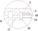
fig. 2 is a schematic structural view of a portion a of a rubber core injection mold according to the present invention;
fig. 3 is a schematic structural diagram of a part B of the rubber core injection mold provided by the utility model.
In the figure: 1. a working plate; 2. a side plate; 3. a top plate; 4. a hydraulic pump; 5. a push plate; 6. inserting plates; 7. a transverse plate; 8. moving the template; 9. fixing a template; 10. positioning a plate; 11. a cavity; 12. a pouring hole; 13. a thimble; 14. pushing the plate; 15. a first spring; 16. a slide plate; 17. clamping a plate; 18. a second spring; 19. pulling a rope; 20. stay cord connector.
Detailed Description
The technical solutions in the embodiments of the present invention will be described clearly and completely with reference to the accompanying drawings in the embodiments of the present invention, and it is obvious that the described embodiments are only some embodiments of the present invention, not all embodiments.
Referring to fig. 1-3, a rubber core injection mold comprises a working plate 1, wherein side plates 2 are welded on two sides of the top of the working plate 1, a top plate 3 is welded on the top of the two side plates 2, a hydraulic pump 4 is fixedly connected to the bottom of the top plate 3, a push plate 5 is fixedly connected to a hydraulic rod of the hydraulic pump 4, two slots are formed in the bottom of the push plate 5, insert plates 6 are clamped in the slots, transverse plates 7 are welded on the bottom of the insert plates 6, a movable mold plate 8 is welded on one side of the two transverse plates 7 close to each other, a fixed mold plate 9 is contacted with the top of the working plate 1, two positioning plates 10 are fixedly connected to the bottom of the fixed mold plate 9, two positioning grooves are formed in the top of the working plate 1, the positioning plates 10 are clamped with the positioning grooves, a cavity 11 is formed in the top of the fixed mold plate 9, sliding mounting has thimble 13 in the thimble hole, the same push pedal 14 of the bottom fixedly connected with of two thimbles 13, the top welding of push pedal 14 has a plurality of first springs 15, the top of first spring 15 welds in the bottom of working plate 1, two spouts have been seted up to the bottom of slurcam 5, sliding mounting has slide 16 in the spout, cardboard 17 has all been welded to one side that two slides 16 kept away from each other, the draw-in groove has all been seted up to one side that two picture pegs 6 are close to each other, cardboard 17 clamps with the draw-in groove mutually, two cardboard 17 one side that are close to each other all weld second spring 18, the one end that two second springs 18 are close to each other welds respectively on the one side inner wall that two spouts are close to each other, the equal fixedly connected with stay.
In this embodiment, the bottom four corners of the working plate 1 are welded with the supporting plates.
In this embodiment, seted up the bolt hole on the curb plate 2, bolt hole female connection has the bolt, and the thread groove has all been seted up to the both sides of fixed die plate 9, and bolt and thread groove threaded connection are convenient for fix fixed die plate 9.
In this embodiment, the number of the first springs 15 is three, so that the push plate 14 can be restored to the original position.
In this embodiment, two adaptive holes are formed in the inner wall of the bottom of the cavity 11, and the top of the ejector pin 13 extends into the adaptive holes and is in sealing contact with the adaptive holes, so that the molded rubber core is subjected to demolding treatment conveniently.
In this embodiment, the same pull cord connector 20 is sewn at the end of the two pull cords 19 adjacent to each other.
In the utility model, when the plastic core is injected, the hydraulic pump 4 is started, the movable mould plate 8 and the fixed mould plate 9 are closed, the melted plastic is guided into the cavity 11 through the pouring hole 12, after the plastic core is shaped by injection, the movable mould plate 8 is separated from the fixed mould plate 9 by starting the hydraulic pump 4, then the push plate 14 is pushed, the push plate 14 extrudes the first spring 15, the push plate 14 drives the thimble 13 to move, the thimble 13 drives the shaped plastic core to move out of the cavity 11, when the shape of the plastic core needs to be injected is changed, two pull ropes 19 are pulled, the pull rope 19 drives the sliding plate 16 to move, the sliding plate 16 extrudes the second spring 18, the sliding plate 16 drives the clamping plate 17 to move, the clamping plate 17 is moved out of the clamping groove, the movable mould plate 8 is taken out, the bolt is screwed down, the fixed mould plate 9 is taken out, the fixed mould plate 9 and the movable mould plate 8 which are matched with the shape of the injection, the method is suitable for injection molding of rubber cores with different shapes.
The basic principles and the main features of the invention and the advantages of the invention have been shown and described above, it will be evident to those skilled in the art that the invention is not limited to the details of the foregoing illustrative embodiments, but that the invention may be embodied in other specific forms without departing from the spirit or essential characteristics of the invention. The present embodiments are therefore to be considered in all respects as illustrative and not restrictive, the scope of the invention being indicated by the appended claims rather than by the foregoing description, and all changes which come within the meaning and range of equivalency of the claims are therefore intended to be embraced therein. Any reference sign in a claim should not be construed as limiting the claim concerned.
Furthermore, it should be understood that although the present description refers to embodiments, not every embodiment may contain only a single embodiment, and such description is for clarity only, and those skilled in the art should integrate the description, and the embodiments may be combined as appropriate to form other embodiments understood by those skilled in the art.
Claims (6)
1. The rubber core injection mold comprises a working plate (1) and is characterized in that side plates (2) are welded on two sides of the top of the working plate (1), a same top plate (3) is welded on the tops of the two side plates (2), a hydraulic pump (4) is fixedly connected with the bottom of the top plate (3), a push plate (5) is fixedly connected onto a hydraulic rod of the hydraulic pump (4), two slots are formed in the bottom of the push plate (5), inserting plates (6) are clamped in the slots, transverse plates (7) are welded at the bottoms of the inserting plates (6), a movable mold plate (8) is welded on one side, close to each other, of the two transverse plates (7), a fixed mold plate (9) is contacted with the top of the working plate (1), two positioning plates (10) are fixedly connected with the bottom of the fixed mold plate (9), two positioning grooves are formed in the top of the working plate (1), the top of a fixed die plate (9) is provided with a die cavity (11), the top of a movable die plate (8) is provided with a pouring hole (12), the top of a working plate (1) is provided with two thimble holes, thimbles (13) are slidably mounted in the thimble holes, the bottoms of the two thimbles (13) are fixedly connected with a same push plate (14), the top of the push plate (14) is welded with a plurality of first springs (15), the top ends of the first springs (15) are welded at the bottom of the working plate (1), the bottom of a push plate (5) is provided with two sliding grooves, sliding plates (16) are slidably mounted in the sliding grooves, clamping plates (17) are welded at the sides of the two sliding plates (16) far away from each other, clamping grooves are arranged at the sides of the two inserting plates (6) close to each other, the clamping plates (17) are clamped with the clamping grooves, second springs (18) are welded at the sides of the two clamping plates (17) close to, one sides of the two sliding plates (16) close to each other are fixedly connected with pull ropes (19).
2. The plastic core injection mold according to claim 1, wherein four corners of the bottom of the working plate (1) are welded with supporting plates.
3. The rubber core injection mold according to claim 1, wherein the side plate (2) is provided with a bolt hole, a bolt is connected with the bolt hole through an internal thread, both sides of the fixed mold plate (9) are provided with screw grooves, and the bolt is connected with the screw grooves through screw threads.
4. A rubber-cored injection mold according to claim 1, characterized in that the number of the first springs (15) is three.
5. The rubber core injection mold according to claim 1, wherein the inner wall of the bottom of the cavity (11) is provided with two fitting holes, and the top of the thimble (13) extends into the fitting holes and is in sealing contact with the fitting holes.
6. The plastic core injection mold according to claim 1, wherein the ends of the two pulling cords (19) adjacent to each other are sewn with the same pulling cord connector (20).
Priority Applications (1)
| Application Number | Priority Date | Filing Date | Title |
|---|---|---|---|
| CN202020580922.5U CN211993998U (en) | 2020-04-18 | 2020-04-18 | Rubber core injection mold |
Applications Claiming Priority (1)
| Application Number | Priority Date | Filing Date | Title |
|---|---|---|---|
| CN202020580922.5U CN211993998U (en) | 2020-04-18 | 2020-04-18 | Rubber core injection mold |
Publications (1)
| Publication Number | Publication Date |
|---|---|
| CN211993998U true CN211993998U (en) | 2020-11-24 |
Family
ID=73416351
Family Applications (1)
| Application Number | Title | Priority Date | Filing Date |
|---|---|---|---|
| CN202020580922.5U Active CN211993998U (en) | 2020-04-18 | 2020-04-18 | Rubber core injection mold |
Country Status (1)
| Country | Link |
|---|---|
| CN (1) | CN211993998U (en) |
Cited By (1)
| Publication number | Priority date | Publication date | Assignee | Title |
|---|---|---|---|---|
| CN113601773A (en) * | 2021-09-30 | 2021-11-05 | 南通鑫晶电子科技有限公司 | Transmission type chip packaging device |
-
2020
- 2020-04-18 CN CN202020580922.5U patent/CN211993998U/en active Active
Cited By (2)
| Publication number | Priority date | Publication date | Assignee | Title |
|---|---|---|---|---|
| CN113601773A (en) * | 2021-09-30 | 2021-11-05 | 南通鑫晶电子科技有限公司 | Transmission type chip packaging device |
| CN113601773B (en) * | 2021-09-30 | 2021-12-07 | 南通鑫晶电子科技有限公司 | Transmission type chip packaging device |
Similar Documents
| Publication | Publication Date | Title |
|---|---|---|
| CN211993998U (en) | Rubber core injection mold | |
| CN106003598B (en) | A kind of cooking machine filter injection mold synchronously carried out using die sinking ejection | |
| CN204183814U (en) | Injection forming mold | |
| CN202727249U (en) | Plastic mold | |
| CN202293233U (en) | Core-pulling mechanism for injection mold with inner reverse fastener | |
| CN203221626U (en) | Embedded movable compression column mold structure | |
| CN214082571U (en) | Double-layer injection mold for polycarbonate car lamp lens | |
| CN206011602U (en) | A kind of pressure difference switch injection mold | |
| CN214266455U (en) | Injection mold capable of automatically demolding | |
| CN211389992U (en) | Mould for lipstick inserts | |
| CN210651717U (en) | Sectional type screw thread pitched roof lateral parting core-pulling mechanism | |
| CN211165057U (en) | New energy automobile spare part injection mold | |
| CN210148666U (en) | Injection mold is used in production of electronic product shell | |
| CN203449560U (en) | Injection mould of automobile fog lamp cover plate | |
| CN203381111U (en) | Injection mould for shell of washing machine | |
| CN113681828A (en) | Split type combined cavity vulcanizing mold for track shock absorber and production method thereof | |
| CN201755894U (en) | Motor cover mold connection hole clamping groove secondary core pulling mechanism | |
| CN216579055U (en) | Mould of mould opening mould core take-off mechanism | |
| CN217916503U (en) | Auto-parts injection mold | |
| CN211251182U (en) | Hot runner plastic mold for automobile production | |
| CN210820609U (en) | Clamp plugging plastic plate forming die | |
| CN218429718U (en) | Injection mold capable of automatically stripping materials for manufacturing car lamp | |
| CN219191170U (en) | Quick fashioned mould for processing plastic dustbin | |
| CN216941666U (en) | Slide structure of upwards loosing core | |
| CN213564127U (en) | Injection mold of pen tube |
Legal Events
| Date | Code | Title | Description |
|---|---|---|---|
| GR01 | Patent grant | ||
| GR01 | Patent grant | ||
| PE01 | Entry into force of the registration of the contract for pledge of patent right | ||
| PE01 | Entry into force of the registration of the contract for pledge of patent right |
Denomination of utility model: A rubber core injection mold Effective date of registration: 20211103 Granted publication date: 20201124 Pledgee: Guangdong Nanhai Rural Commercial Bank branch branch of Limited by Share Ltd. Pledgor: FOSHAN SHUNDE TIMMAS ELECTRONIC CO.,LTD. Registration number: Y2021980011868 |