CN211990761U - Frog center die forging forming die - Google Patents
Frog center die forging forming die Download PDFInfo
- Publication number
- CN211990761U CN211990761U CN202020476615.2U CN202020476615U CN211990761U CN 211990761 U CN211990761 U CN 211990761U CN 202020476615 U CN202020476615 U CN 202020476615U CN 211990761 U CN211990761 U CN 211990761U
- Authority
- CN
- China
- Prior art keywords
- die
- forging
- base
- upper die
- lower die
- Prior art date
- Legal status (The legal status is an assumption and is not a legal conclusion. Google has not performed a legal analysis and makes no representation as to the accuracy of the status listed.)
- Active
Links
Images


Abstract
The utility model relates to a frog center die forging forming die, this mould include die holder, lower mould, left module, right module, upper die base, rings and go up the mould. The center of the top surface of the lower die base is embedded with a lower die in a matching way, and the upper part of the lower die is used for placing a blank; the left module and the right module are arranged on the top surface of the lower die base in a left-right symmetrical matching manner; an upper die cavity is formed in the upper die base in a matching mode from the center of the bottom of the upper die base; the left inner cavity wall and the right inner cavity wall of the upper die cavity are respectively connected with the outer side surfaces of the left die block and the right die block in a sliding fit manner; the upper end of the hanging ring is hung on the upper die base in a matching manner, and the lower end of the hanging ring is rigidly connected with the upper parts of the left module and the right module; the upper die is matched and fixedly arranged at the bottom of the inner cavity of the upper die cavity and corresponds to the lower die. The utility model discloses think about rationally, the deflection of forging the fork heart is little, can not only realize few, the forging of no overlap, still when reducing the mould station, has reduced required shaping tonnage, and the stability of forging and pressing is good and forging and pressing product quality is high.
Description
Technical Field
The utility model belongs to the technical field of forge processing, concretely relates to frog heart die forging forming die.
Background
In the existing embedded wing rail type combined frog (integral wing rail), a forged frog center is made of two materials, namely bainite alloy steel and high manganese steel. The alloy steel material has higher hardness, and the high manganese steel has difficult processing of the two materials due to obvious work hardening tendency, low processing efficiency and high cost. The market demand of frog products adopting the structure shows a trend of rising year by year, so that the manufacturing cost is reduced by developing a die forging forming process and reducing the machining allowance of a forging piece.
In the retrieved publication 1, "a method for integral die forging of frog", a die forging forming method of frog is disclosed, which adopts a die type of upper and lower divided dies to forge a rolled round steel bar twice through pre-forging and finish forging after wedge cross rolling cogging. Its product with the utility model provides a forging fork heart belongs to same trade, but its structure, the die forging method and the mould structure of adoption and the utility model discloses all inequality.
Retrieved publication 2 double-station die forging forming method for austenite high manganese steel combined frog insert discloses a combined frog insert (point rail) structure and a die forging forming method, the product structure is similar to the utility model, a die structure form of upper and lower split dies is adopted, and die forging forming of a forge piece is completed through one-station die forging forming and two-station trimming finishing. This scheme needs two stations because forging structure reason, has great forging overlap, need cut edge at the second station and maintain, is unfavorable for improving material utilization.
Disclosure of Invention
To the problem that exists among the above-mentioned background art, the utility model provides a conceive rationally, the deflection of forging the fork heart is little, can not only realize few, no overlap forging, still when reducing the mould station, has reduced required shaping tonnage, and the stability of forging and pressing is good and forging and pressing product high quality frog heart die forging forming die.
The technical scheme of the utility model as follows:
the frog center die forging forming die comprises a lower die holder, a lower die, a left die block, a right die block, an upper die holder, a lifting ring and an upper die; the lower die is embedded in the center of the top surface of the lower die base in a matching manner, and the upper part of the lower die is used for placing blanks; the left module and the right module are arranged on the top surface of the lower die base in a left-right symmetrical matching manner; the upper die base is arranged right above the lower die base in a matching mode, the top of the upper die base is fixedly assembled with a die forging forming press, and an upper die cavity is formed in the center of the bottom of the upper die base in a matching mode; the left inner cavity wall and the right inner cavity wall of the upper die cavity are respectively connected with the outer side surfaces of the left die block and the right die block in a sliding fit manner; the upper end of the lifting ring is hung on the upper die base in a matched mode, and the lower end of the lifting ring is rigidly connected with the upper portions of the left module and the right module; the upper die is matched and fixedly arranged at the bottom of the inner cavity of the upper die cavity and corresponds to the lower die arranged on the lower die seat.
The frog center die forging forming die, wherein: the inclined plane and the vertical direction form an included angle of 10-30 degrees.
The frog center die forging forming die, wherein: the upper end of the hanging ring is provided with a capsule-shaped through hole which is communicated with the front and the back in a matching way; a connecting pin is arranged in the capsule-shaped sliding chute in a matching and sliding manner; one end of the connecting pin extends out of the capsule-shaped sliding groove, and the extending end of the connecting pin is fixedly connected with the upper die base.
The frog center die forging forming die, wherein: the center of the top surface of the lower die base is provided with a lower die groove along the vertical direction in a matching way; the lower die is matched and embedded and fixed in the lower die groove.
Use the utility model discloses forming die's a frog heart die forging method, its concrete flow is: (1) heating a rolled raw material or a freely forged and unbaked center rail blank after die casting to 1130-1230 ℃; (2) horizontally placing the heated blank on a lower die; (3) the upper die base moves downwards to drive the upper die, the left die block and the right die block to simultaneously close the dies once, namely, the dies are synchronously closed from the left direction, the right direction and the top surface, and die forging forming of the integral wing rail type forging fork center is realized.
Has the advantages that:
the utility model discloses frog heart die forging forming die structural design is simple, reasonable, adopts the whole die forging method and adopts the rectangular cross section blank to forge and press, has reduced the deflection of forging the fork heart, forges the surplus piece through reasonable setting, has realized few, no overlap and has forged, when reducing the mould station, has reduced required shaping tonnage.
The utility model discloses frog heart die forging forming method adopts a station, improves unnecessary metal flow direction, accomplishes few, the shaping of no overlap, improves material utilization's purpose. The utility model discloses the blank of frog heart die forging forming method forging and pressing is the rectangular cross section blank, can adopt the continuous casting billet to roll the material, also can adopt the die cast ingot free forging cogging to carry out the prefabricated base, adds the die cavity after heating to the start forging temperature in, and the forging is once obtained to the simultaneous movement compound die.
The utility model discloses frog heart die forging forming method is at compound die pressing in-process, and the position of lower part mould remains unchanged, the vertical downstream of upper portion mould, and left and right side mould is in step opposite directions, all towards the work piece motion, has guaranteed the stability and the product quality of forging and pressing.
Drawings
Fig. 1 is the die-forging forming die for frog center and the schematic drawing of the die assembly of the blank.
Fig. 2 is a schematic structural view of a certain type of integral wing rail type forged fork center part in the embodiment of the present invention.
Fig. 3 is the embodiment of the utility model provides an according to the fork heart forge hot piece structure sketch map that fig. 2 drawn.
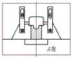
Fig. 4 is the embodiment of the utility model provides an according to fig. 3 hot forging size, the utility model discloses frog heart die forging forming die and blank A are to compound die state sketch map.
Fig. 5 is a schematic diagram of the die-forging die for frog center die forging and the die-closing state of the blank B-B according to the size of the hot forging piece shown in fig. 3 in the embodiment of the present invention.
Fig. 6 is the embodiment of the present invention, according to the size of the hot forging piece shown in fig. 3, the die forging forming die for frog center die forging and the C-C blank are in the die-closing state.
Fig. 7 is the embodiment of the present invention, according to the size of the hot forging piece shown in fig. 3, the die forging forming die for frog center die forging and the die closing state of the blank D-D to the section are schematically illustrated.
Fig. 8 is the embodiment of the present invention, according to the size of the hot forging piece shown in fig. 3, the die forging forming die for frog center die forging and the die closing state of the blank E-E to the section are schematically shown.
Detailed Description
The invention will be further elucidated with reference to the drawings and specific embodiments. Following embodiment is the embodiment of the preferred of the utility model, not be used for the restriction the utility model discloses implement the scope, die forging method and mould structure be applicable to the whole wing rail formula forging fork heart of arbitrary model. Therefore, all equivalent changes made by the claims of the present invention should be included in the scope of the claims of the present invention.
As shown in fig. 1, the utility model discloses frog heart die forging forming die, including die holder 1, lower mould 2, left module 3, right module 4, upper die base 5, rings 6 and last mould 7.
The top surface center of this lower bolster 1 has seted up lower mould recess 11 along vertical direction matching, and this lower mould 2 matches to inlay to establish and is fixed in the lower mould recess 11 of this lower bolster 1 and upper portion is used for placing blank 8.
The left module 3 is matched and fixed at the left side of the top surface of the lower die holder 1, the right module 4 is matched and fixed at the right side of the top surface of the lower die holder 1, and the left module 3 and the right module 4 are symmetrically arranged; the outer side surfaces of the left module 3 and the right module 4 are both of an inclined surface structure.
The upper die base 5 is arranged right above the lower die base 1 in a matching way, and the top of the upper die base is assembled and fixed with a die forging press (the tonnage is less than 1 ten thousand tons); the upper die base 5 is provided with an upper die cavity 51 from the center of the bottom in a matching way; the left inner cavity wall and the right inner cavity wall of the upper die cavity 51 are of inclined surface structures and are respectively matched with the transverse outer side inclined surfaces of the left die block 3 and the right die block 4, the upper die base 5 is connected with the outer sides of the left die block 3 and the right die block 4 in an inclined surface sliding fit mode through the inner cavity walls of the left side and the right side of the upper die cavity 51, and the inclined surfaces and the vertical direction form an included angle of 10-30 degrees.
The hanging ring 6 is arranged at the upper parts of the left module 3 and the right module 4 in a matching way, the upper end of the hanging ring is suspended on the upper die base 5, and the lower end of the hanging ring is rigidly connected with the upper parts of the left module 3 and the right module 4; wherein, the upper end of the hanging ring 6 is provided with a capsule-shaped through hole 61 which is communicated with the front and the back in a matching way; a connecting pin 62 is arranged in the capsule-shaped sliding groove 61 in a matching and sliding manner; one end of the connecting pin 62 extends out of the capsule-shaped sliding groove 61 and the extending end is fixedly connected with the upper die base 5.
The upper die 7 is fixedly mounted at the center of the inner cavity bottom of the upper die cavity 51 of the upper die base 5 in a matching manner, and the upper die 7 corresponds to the lower die 2 mounted on the lower die base 1 in a matching manner.
The utility model discloses frog heart die forging forming die's theory of operation:
fig. 1 shows a state of opening the mold, when a workpiece needs to be pressed by closing the mold, the upper mold base 5 moves vertically and downwardly, and the left inner cavity wall of the upper mold cavity 51 of the upper mold base 5, which is an inclined surface, provides a horizontal thrust force for the left mold block 3, so that the left mold block 3 moves towards the blank 8; the right inner cavity wall of the upper die cavity 51 of the upper die holder 5 which is an inclined plane provides a horizontal leftward thrust for the right die block 4, so that the right die block 4 moves towards the blank 8; when the upper die holder 5 moves downwards to the joint with the top surface of the lower die holder 1, the upper die 7, the left die block 3 and the right die block 4 also move simultaneously to the theoretical die assembly displacement, and the pressing of the workpiece is realized.
Based on the frog center die forging forming die, the specific flow is as follows:
(1) heating a rolled raw material or a freely forged and unbaked center rail blank after die casting to 1130-1230 ℃;
(2) horizontally placing the heated blank on a lower die 7;
(3) the upper die 7, the left die block 3 and the right die block 4 are driven to simultaneously close the dies once by the downward movement of the upper die base 5, namely, the dies are synchronously moved from the left direction, the right direction and the top surface to close the dies, and the die forging forming of the integral wing rail type forging fork center is realized.
The embodiment of the utility model provides an in the whole wing rail formula forging fork heart of certain model that fig. 2 is shown, according to its structural usage, can divide into the I district that contains wing rail and heart rail from the front to the back in proper order, do not contain the II districts of wing rail and mainly play III districts of erection joint effect. Wherein the cross-sectional area of the area I is larger than that of the area II, the area II is larger than that of the area III, and the integral wing rail type forging fork center of any type has the common characteristics.
The embodiment of the utility model provides an in 3 for according to the fork heart forge hot piece picture that drawing 2 draw, for reducing forming pressure, increased in III districts and forged surplus piece, make the section size in III districts and II district be close to the metal deflection in III districts has been reduced.
The utility model discloses a whole die forging method adopts the rectangular cross section blank, has reduced the deflection of forging the fork heart, forges the surplus piece through reasonable setting, has realized few, no overlap and has forged, when reducing the mould station, has reduced required shaping tonnage.
Claims (4)
1. The utility model provides a frog heart die forging forming die which characterized in that: the die comprises a lower die base, a lower die, a left die block, a right die block, an upper die base, a lifting ring and an upper die;
the lower die is embedded in the center of the top surface of the lower die base in a matching manner, and the upper part of the lower die is used for placing blanks;
the left module and the right module are arranged on the top surface of the lower die base in a left-right symmetrical matching manner;
the upper die base is arranged right above the lower die base in a matching mode, the top of the upper die base is fixedly assembled with a die forging forming press, and an upper die cavity is formed in the center of the bottom of the upper die base in a matching mode; the left inner cavity wall and the right inner cavity wall of the upper die cavity are respectively connected with the outer side surfaces of the left die block and the right die block in a sliding fit manner;
the upper end of the lifting ring is hung on the upper die base in a matched mode, and the lower end of the lifting ring is rigidly connected with the upper portions of the left module and the right module;
the upper die is matched and fixedly arranged at the bottom of the inner cavity of the upper die cavity and corresponds to the lower die arranged on the lower die seat.
2. The frog center die forging forming die of claim 1, wherein: the inclined plane and the vertical direction form an included angle of 10-30 degrees.
3. The frog center die forging forming die of claim 1, wherein: the upper end of the hanging ring is provided with a capsule-shaped through hole which is communicated with the front and the back in a matching way; a connecting pin is arranged in the capsule-shaped sliding chute in a matching and sliding manner; one end of the connecting pin extends out of the capsule-shaped sliding groove, and the extending end of the connecting pin is fixedly connected with the upper die base.
4. The frog center die forging forming die of claim 1, wherein: the center of the top surface of the lower die base is provided with a lower die groove along the vertical direction in a matching way; the lower die is matched and embedded and fixed in the lower die groove.
Priority Applications (1)
| Application Number | Priority Date | Filing Date | Title |
|---|---|---|---|
| CN202020476615.2U CN211990761U (en) | 2020-04-03 | 2020-04-03 | Frog center die forging forming die |
Applications Claiming Priority (1)
| Application Number | Priority Date | Filing Date | Title |
|---|---|---|---|
| CN202020476615.2U CN211990761U (en) | 2020-04-03 | 2020-04-03 | Frog center die forging forming die |
Publications (1)
| Publication Number | Publication Date |
|---|---|
| CN211990761U true CN211990761U (en) | 2020-11-24 |
Family
ID=73403680
Family Applications (1)
| Application Number | Title | Priority Date | Filing Date |
|---|---|---|---|
| CN202020476615.2U Active CN211990761U (en) | 2020-04-03 | 2020-04-03 | Frog center die forging forming die |
Country Status (1)
| Country | Link |
|---|---|
| CN (1) | CN211990761U (en) |
-
2020
- 2020-04-03 CN CN202020476615.2U patent/CN211990761U/en active Active
Similar Documents
| Publication | Publication Date | Title |
|---|---|---|
| CN101508004B (en) | Sedan gear-box axle piece cold finish-forging formation method and die | |
| CN102513444B (en) | Composite flanging mechanism of stamping die | |
| CN101376141B (en) | Press forming method of automobile hub and matched forming mold thereof | |
| CN204700224U (en) | The vertical split cast mounting of multinomial die forging | |
| CN202752523U (en) | Automobile steering knuckle multidirectional die forging precision forging forming die | |
| CN103121075B (en) | Hot forging method for transmission shaft yoke with horizontal yoke part | |
| CN102513498A (en) | Precise forging method for automobile driven spiral bevel gear | |
| CN103357804A (en) | Damping type flow control forming process and die for aluminium-alloy rib-plate forging | |
| CN104907475A (en) | Integral forging mold of valve body with flanges, and forging method | |
| CN101579805A (en) | Hot die-pressing production technique of shackle and die thereof | |
| CN203265502U (en) | Hot forging device for transmission shaft joint fork with horizontal fork part | |
| CN108097855B (en) | A kind of railway frog solid forging method | |
| CN102836941B (en) | Production method of forging piece | |
| CN108672646A (en) | A kind of iron seat contour forging technique | |
| CN211990761U (en) | Frog center die forging forming die | |
| CN109175175A (en) | A kind of vehicle steering ball joint precision heat processing and forming method | |
| CN204867260U (en) | Flanged valve body solid forging mould | |
| CN112475180A (en) | Forging die and method for step shaft type forge piece | |
| CN111451430A (en) | Frog center die forging forming die and method | |
| CN104550609B (en) | A kind of closed-die extrusion forging technology mould | |
| CN110000321A (en) | The forge moulding technology of aluminum alloy mobile phone shell | |
| CN110695286A (en) | High manganese steel frog insert double-station die forging forming die and forming method | |
| CN205668025U (en) | A kind of drive axle U-shaped shock absorber support mould | |
| CN201470798U (en) | One-step forming mould for alien spring | |
| CN201644691U (en) | Composite forming die mold of complicated axial forging with shaft shoulder and flange plate |
Legal Events
| Date | Code | Title | Description |
|---|---|---|---|
| GR01 | Patent grant | ||
| GR01 | Patent grant |