CN211990446U - Double-spinning-wheel spinning machine heat dissipation device - Google Patents
Double-spinning-wheel spinning machine heat dissipation device Download PDFInfo
- Publication number
- CN211990446U CN211990446U CN202020338129.4U CN202020338129U CN211990446U CN 211990446 U CN211990446 U CN 211990446U CN 202020338129 U CN202020338129 U CN 202020338129U CN 211990446 U CN211990446 U CN 211990446U
- Authority
- CN
- China
- Prior art keywords
- fixedly connected
- spinning
- connecting rod
- work piece
- driving motor
- Prior art date
- Legal status (The legal status is an assumption and is not a legal conclusion. Google has not performed a legal analysis and makes no representation as to the accuracy of the status listed.)
- Active
Links
Images

Abstract
The utility model discloses a double-spinning-wheel spinning-lathe heat abstractor, the drill jig comprises a base station, the top fixedly connected with driving motor and the installation piece of base station, driving motor's output fixedly connected with transfer line, the side of installation piece is rotated and is connected with first hydraulic stem, the output fixedly connected with of first hydraulic stem and the connecting rod that transfer line horizontal position corresponds, be equipped with the work piece between transfer line and the connecting rod. The utility model discloses, through the cooperation work between the heat dissipation mechanism, pivoted driving motor has driven the rotation of flabellum when driving the work piece pivoted, makes the flabellum carry out timely heat dissipation to the work piece, and the effectual centre wheel and the work piece of having avoided rubs always, and the heat conducts on the work piece, makes the work piece except that the processing position also always be in the condition of the state of generating heat, has promoted final shaping effect greatly, further accelerated the cooling of the work piece under the state of generating heat, has promoted work efficiency.
Description
Technical Field
The utility model relates to a spinning-lathe technical field especially relates to a double-spinning-wheel spinning-lathe heat abstractor.
Background
The spinning machine belongs to metal plastic forming machinery, realizes automatic processing and control, is multifunctional and universal equipment, has high precision and reliability, and has a CAD drawing programming function, a core mold copying function and a recording function.
The spinning machine works to extrude, polish and shape a workpiece, when the spinning machine rotates and shapes the workpiece, the center wheel and the workpiece are in friction all the time, heat is conducted on the workpiece, the workpiece is in a heating state all the time except a machining position, integral forming of the workpiece is affected, in addition, the existing center wheel is fixed on the spinning machine, workpieces of different sizes cannot be processed in time, and therefore the double-spinning-wheel spinning machine heat dissipation device is provided.
SUMMERY OF THE UTILITY MODEL
The utility model aims at solving among the prior art work piece and also being in the state of generating heat except that the processing position always, influencing the whole fashioned shortcoming of work piece, and the double-spinning-wheel spinning-lathe heat abstractor who provides makes the flabellum carry out timely heat dissipation to the work piece, has promoted final shaping effect.
In order to achieve the above purpose, the utility model adopts the following technical scheme:
the utility model provides a double-spinning-wheel spinning-lathe heat abstractor, includes the base station, the top fixedly connected with driving motor and the installation piece of base station, driving motor's output fixedly connected with transfer line, the side of installation piece is rotated and is connected with first hydraulic stem, the output fixedly connected with of first hydraulic stem and the connecting rod that transfer line horizontal position corresponds, be equipped with the work piece between transfer line and the connecting rod, the top of base station is equipped with two first adjustment mechanism, be connected with second adjustment mechanism and installation mechanism on the first adjustment mechanism, the last heat dissipation mechanism that is connected with of driving motor.
Preferably, first adjustment mechanism includes second hydraulic stem and the first guide block of fixed connection at the base station top, first slip mouth has been seted up on the first guide block, the inside wall sliding connection of first slip mouth has the installation lug, the top fixedly connected with second guide block of installation lug, the output of second hydraulic stem and the side fixed connection of second guide block.
Preferably, the second adjusting mechanism comprises a second sliding opening formed in the second guide block, the inner side wall of the second sliding opening is connected with a mounting disc in a sliding mode, a third hydraulic rod is fixedly connected to the side face of the top of the second guide block, and the output end of the third hydraulic rod is fixedly connected with the side face of the mounting disc.
Preferably, the mounting mechanism comprises a mounting opening formed in the side face of the mounting disc, a connecting rod is inserted into the inner side wall of the mounting opening, a mounting bolt is inserted into the mounting opening through threads, the mounting bolt penetrates through the inside of the connecting rod and is in threaded connection with the connecting rod, a rotating block is rotatably connected to the top of the mounting bolt and is connected with the mounting disc through a connecting rope, a center wheel is fixedly connected to the side face of the connecting rod, and the center wheel is in abutting contact with the side face of the workpiece.
Preferably, two of the second guide blocks are arranged obliquely relative to each other.
Preferably, the heat dissipation mechanism comprises a plurality of fan blades fixedly connected to the output end of the driving motor, and the fan blades are located on the side face of the workpiece.
Compared with the prior art, the beneficial effects of the utility model are that:
1. through the cooperation work between the heat dissipation mechanism, pivoted driving motor has driven the rotation of flabellum when driving the work piece pivoted, makes the flabellum carry out timely heat dissipation to the work piece, has effectually avoided centre wheel and work piece to rub always, and the heat conducts on the work piece, makes the work piece except that the processing position also be in the condition of the state of generating heat always, has promoted final shaping effect greatly, further accelerated the cooling of work piece under the state of generating heat, promoted work efficiency.
2. Through the cooperation work between the installation mechanism, make the construction bolt unscrew from connecting rod upper thread, the connecting rod that can change friction all the time like this, guarantee the center wheel on the connecting rod and to the support of work piece and press and be in best effect, the effectual efficiency that has promoted work of quick simple change connecting rod.
Drawings
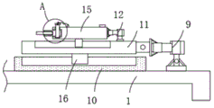
Fig. 1 is a schematic structural view of a heat dissipation device of a spinning machine with double spinning rollers according to the present invention;
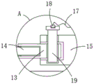
fig. 2 is a schematic structural view of a second guide block of a heat dissipation device of a spinning machine with double spinning rollers according to the present invention;
fig. 3 is an enlarged view of a portion a in fig. 2.
In the figure: the fan blade mounting device comprises a base platform 1, a driving motor 2, a transmission rod 3, a first hydraulic rod 4, a connecting rod 5, a mounting block 6, fan blades 7, a workpiece 8, a second hydraulic rod 9, a first guide block 10, a second guide block 11, a third hydraulic rod 12, a connecting rod 13, a center wheel 14, a mounting disc 15, a mounting lug 16, a connecting rope 17, a rotating block 18 and a mounting bolt 19.
Detailed Description
The technical solutions in the embodiments of the present invention will be described clearly and completely with reference to the accompanying drawings in the embodiments of the present invention, and it is obvious that the described embodiments are only some embodiments of the present invention, not all embodiments.
Referring to fig. 1-3, a heat dissipation device for a double-spinning-wheel spinning machine comprises a base platform 1, a driving motor 2 and an installation block 6 are fixedly connected to the top of the base platform 1, a transmission rod 3 is fixedly connected to the output end of the driving motor 2, a first hydraulic rod 4 is rotatably connected to the side surface of the installation block 6, a connecting rod 5 corresponding to the horizontal position of the transmission rod 3 is fixedly connected to the output end of the first hydraulic rod 4, a workpiece 8 is arranged between the transmission rod 3 and the connecting rod 5, two first adjusting mechanisms are arranged on the top of the base platform 1, each first adjusting mechanism comprises a second hydraulic rod 9 and a first guide block 10 which are fixedly connected to the top of the base platform 1, a first sliding opening is formed in the first guide block 10, an installation bump 16 is slidably connected to the inner side wall of the first sliding opening, a second guide block 11 is fixedly connected to the top of the installation bump 16, and the output end of, through the cooperation between the first adjusting mechanism and the second adjusting mechanism, the central wheel 14 moves on the tracks of the first sliding port and the second sliding port, so that the two central wheels 14 spin the rotating workpiece 8, and the workpiece 8 is machined.
The first adjusting mechanism is connected with a second adjusting mechanism and an installing mechanism, the second adjusting mechanism comprises a second sliding opening arranged on a second guide block 11, the inner side wall of the second sliding opening is connected with an installing disc 15 in a sliding mode, the side face of the top of the second guide block 11 is fixedly connected with a third hydraulic rod 12, the output end of the third hydraulic rod 12 is fixedly connected with the side face of the installing disc 15, the installing mechanism comprises an installing opening arranged on the side face of the installing disc 15, a connecting rod 13 is inserted into the inner side wall of the installing opening, an installing bolt 19 is inserted into the installing opening in a threaded mode, the installing bolt 19 penetrates through the inner portion of the connecting rod 13 and is in threaded connection with the connecting rod 13, the top of the installing bolt 19 is rotatably connected with a rotating block 18, the rotating block 18 is connected with the installing disc 15 through a connecting rope 17, a center wheel 14 is fixedly connected to the side face of the connecting rod 13, the center wheel 14 is in pressing contact, through the cooperation work between the installation mechanisms, the installation bolt 19 is unscrewed from the threads on the connecting rod 13, so that the connecting rod 13 which is always rubbed can be replaced at any time, the pressing effect of the central wheel 14 on the connecting rod 13 on the workpiece 8 is ensured to be in the best effect, and the connecting rod 13 is replaced quickly and simply, so that the work efficiency is effectively improved.
Be connected with heat dissipation mechanism on driving motor 2, heat dissipation mechanism includes a plurality of flabellum 7 of fixed connection on driving motor 2 output, flabellum 7 is located work piece 8's side, cooperation work through between the heat dissipation mechanism, pivoted driving motor 2 has driven the rotation of flabellum 7 when driving work piece 8 pivoted, make flabellum 7 carry out timely heat dissipation to work piece 8, the effectual centre wheel 14 of having avoided rubs with work piece 8 always, the heat conducts on work piece 8, make work piece 8 also be in the condition of the state of generating heat all the time except that the processing position, final shaping effect has been promoted greatly, further accelerated the cooling of work piece 8 under the state of generating heat, and the work efficiency is improved.
The utility model discloses in, place work piece 8 between connecting rod 5 and transfer line 3, drive first hydraulic stem 4 and make the output extrusion connecting rod 5 of first hydraulic stem 4 drive connecting rod 5 and transfer line 3 support tightly to work piece 8, then open the switch of driving motor 2 power, make driving motor 2's output drive transfer line 3 rotate, corresponding connecting rod 5 drives first hydraulic stem 4 and rotates on installation piece 6, makes work piece 8 rotate.
At this time, the switch of the power supply of the second hydraulic rod 9 and the third hydraulic rod 12 is opened, so that the output end of the second hydraulic rod 9 drives the mounting bump 16 on the second guide block 11 to slide on the first sliding port on the first guide block 10, the output end of the third hydraulic rod 12 drives the mounting disc 15 to slide on the second sliding port on the second guide block 11, so that the second guide block 11 and the mounting disc 15 continuously move along the tracks of the first sliding port and the second sliding port, the corresponding central wheel 14 on the mounting disc 15 continuously moves along the tracks of the first sliding port and the second sliding port, the position of the central wheel 14 in extrusion contact with the workpiece 8 is continuously adjusted through the continuous movement of the central wheel 14, and the rotating workpiece 8 is extruded by the central wheel 14 to realize the effect of spinning the workpiece 8.
Meanwhile, the output end of the rotation driving motor 2 drives the fan blades 7 to rotate, so that the temperature of the whole workpiece 8 is in a lower state.
The above, only be the concrete implementation of the preferred embodiment of the present invention, but the protection scope of the present invention is not limited thereto, and any person skilled in the art is in the technical scope of the present invention, according to the technical solution of the present invention and the utility model, the concept of which is equivalent to replace or change, should be covered within the protection scope of the present invention.
Claims (6)
1. The utility model provides a double-spinning-wheel spinning-lathe heat abstractor, includes base station (1), its characterized in that, the top fixedly connected with driving motor (2) and the installation piece (6) of base station (1), the output fixedly connected with transfer line (3) of driving motor (2), the side of installation piece (6) is rotated and is connected with first hydraulic stem (4), the output fixedly connected with of first hydraulic stem (4) has connecting rod (5) that correspond with transfer line (3) horizontal position, be equipped with work piece (8) between transfer line (3) and connecting rod (5), the top of base station (1) is equipped with two first adjustment mechanism, be connected with second adjustment mechanism and installation mechanism on the first adjustment mechanism, be connected with heat dissipation mechanism on driving motor (2).
2. The heat dissipation device of a spinning roller with double spinning rollers as claimed in claim 1, wherein the first adjusting mechanism comprises a second hydraulic rod (9) and a first guide block (10) which are fixedly connected to the top of the base (1), the first guide block (10) is provided with a first sliding opening, the inner side wall of the first sliding opening is slidably connected with an installation bump (16), the top of the installation bump (16) is fixedly connected with a second guide block (11), and the output end of the second hydraulic rod (9) is fixedly connected with the side face of the second guide block (11).
3. The heat dissipation device of a double-spinning-wheel spinning machine according to claim 2, wherein the second adjusting mechanism comprises a second sliding opening formed on the second guide block (11), the inner side wall of the second sliding opening is connected with a mounting disc (15) in a sliding manner, a third hydraulic rod (12) is fixedly connected to the side surface of the top of the second guide block (11), and the output end of the third hydraulic rod (12) is fixedly connected with the side surface of the mounting disc (15).
4. The heat dissipation device of a double-spinning-wheel spinning machine as claimed in claim 3, wherein the mounting mechanism comprises a mounting opening formed in the side face of the mounting disc (15), a connecting rod (13) is inserted into the inner side wall of the mounting opening, a mounting bolt (19) is inserted into the mounting opening in a threaded manner, the mounting bolt (19) penetrates through the inside of the connecting rod (13) and is in threaded connection with the connecting rod (13), a rotating block (18) is rotatably connected to the top of the mounting bolt (19), the rotating block (18) is connected with the mounting disc (15) through a connecting rope (17), a center wheel (14) is fixedly connected to the side face of the connecting rod (13), and the center wheel (14) is in pressing contact with the side face of the workpiece (8).
5. A heat sink device for a twin-screw spinning machine according to claim 3, wherein said second guide blocks (11) are disposed obliquely with respect to each other.
6. The heat sink of a spinning roller as claimed in claim 1, wherein the heat sink comprises a plurality of fan blades (7) fixedly connected to the output end of the driving motor (2), and the fan blades (7) are located on the side of the workpiece (8).
Priority Applications (1)
| Application Number | Priority Date | Filing Date | Title |
|---|---|---|---|
| CN202020338129.4U CN211990446U (en) | 2020-03-18 | 2020-03-18 | Double-spinning-wheel spinning machine heat dissipation device |
Applications Claiming Priority (1)
| Application Number | Priority Date | Filing Date | Title |
|---|---|---|---|
| CN202020338129.4U CN211990446U (en) | 2020-03-18 | 2020-03-18 | Double-spinning-wheel spinning machine heat dissipation device |
Publications (1)
| Publication Number | Publication Date |
|---|---|
| CN211990446U true CN211990446U (en) | 2020-11-24 |
Family
ID=73429859
Family Applications (1)
| Application Number | Title | Priority Date | Filing Date |
|---|---|---|---|
| CN202020338129.4U Active CN211990446U (en) | 2020-03-18 | 2020-03-18 | Double-spinning-wheel spinning machine heat dissipation device |
Country Status (1)
| Country | Link |
|---|---|
| CN (1) | CN211990446U (en) |
Cited By (1)
| Publication number | Priority date | Publication date | Assignee | Title |
|---|---|---|---|---|
| CN113560413A (en) * | 2021-07-21 | 2021-10-29 | 深圳市威纳盛五金工艺品有限公司 | Spinning device and method for metal artwork processing |
-
2020
- 2020-03-18 CN CN202020338129.4U patent/CN211990446U/en active Active
Cited By (1)
| Publication number | Priority date | Publication date | Assignee | Title |
|---|---|---|---|---|
| CN113560413A (en) * | 2021-07-21 | 2021-10-29 | 深圳市威纳盛五金工艺品有限公司 | Spinning device and method for metal artwork processing |
Similar Documents
| Publication | Publication Date | Title |
|---|---|---|
| CN211990446U (en) | Double-spinning-wheel spinning machine heat dissipation device | |
| CN211101695U (en) | Possess drilling machine that carries out multiaspect processing to work piece | |
| CN214979348U (en) | Automatic drilling machine is used in processing of drilling high efficiency's brake block | |
| CN2301282Y (en) | Full-automatic convex-concave copying milling machine | |
| CN218081389U (en) | Gearbox shell boring device | |
| CN111055143A (en) | Clamp for machine manufacturing | |
| CN214557641U (en) | A trompil device for forging processing of ball valve end cover | |
| CN114871509A (en) | Gear shaping machining device for star wheel and outer teeth of transmission isolator | |
| CN113458460A (en) | Perforating device for machining | |
| CN113829068A (en) | Perforating device with polishing function for automatic machining of automobile parts | |
| CN113732884A (en) | Grinding device for manufacturing mechanical parts | |
| CN206998515U (en) | Outside automatically grinding polishing machine in cylinder plastic parts | |
| CN217254366U (en) | Drilling and tapping equipment for machining shell | |
| CN218638307U (en) | Double-spinning-wheel profiling spinning machine for producing automobile parts | |
| CN218696871U (en) | Forming device for water conservancy pipeline | |
| CN220480899U (en) | Valve rod processing machine tool | |
| CN220902750U (en) | Automatic burr cutting pneumatic vertical lathe | |
| CN217512935U (en) | Numerical control planer convenient to clearance waste material | |
| CN219292831U (en) | Yaw brake disc grinds and decreases manufacturing device with cutting insert again | |
| CN214559481U (en) | Machining equipment for cloud manufacturing | |
| CN113245941B (en) | Multi-angle electromagnetic valve nozzle machining integrated device and nozzle machining process | |
| CN219380017U (en) | A vertical digit control machine tool for die carrier processing | |
| CN210425689U (en) | Cooling device for building steel plate machining | |
| CN220196364U (en) | Machining tool with uniform stress | |
| CN216398073U (en) | Machining center for precision casting finish machining |
Legal Events
| Date | Code | Title | Description |
|---|---|---|---|
| GR01 | Patent grant | ||
| GR01 | Patent grant |