CN211987798U - Dust suppression device for coal mining - Google Patents
Dust suppression device for coal mining Download PDFInfo
- Publication number
- CN211987798U CN211987798U CN202020464168.9U CN202020464168U CN211987798U CN 211987798 U CN211987798 U CN 211987798U CN 202020464168 U CN202020464168 U CN 202020464168U CN 211987798 U CN211987798 U CN 211987798U
- Authority
- CN
- China
- Prior art keywords
- dust
- box
- water
- falling
- air
- Prior art date
- Legal status (The legal status is an assumption and is not a legal conclusion. Google has not performed a legal analysis and makes no representation as to the accuracy of the status listed.)
- Expired - Fee Related
Links
- 239000000428 dust Substances 0.000 title claims abstract description 131
- 230000001629 suppression Effects 0.000 title claims abstract description 25
- 239000003245 coal Substances 0.000 title claims abstract description 23
- 238000005065 mining Methods 0.000 title claims abstract description 19
- XLYOFNOQVPJJNP-UHFFFAOYSA-N water Substances O XLYOFNOQVPJJNP-UHFFFAOYSA-N 0.000 claims abstract description 144
- 238000003860 storage Methods 0.000 claims abstract description 20
- 239000007921 spray Substances 0.000 claims abstract description 9
- 238000001914 filtration Methods 0.000 claims description 13
- 239000003651 drinking water Substances 0.000 claims 2
- 235000020188 drinking water Nutrition 0.000 claims 2
- 238000005086 pumping Methods 0.000 abstract description 28
- 238000005507 spraying Methods 0.000 abstract description 10
- 239000003595 mist Substances 0.000 abstract description 6
- 230000008878 coupling Effects 0.000 description 4
- 238000010168 coupling process Methods 0.000 description 4
- 238000005859 coupling reaction Methods 0.000 description 4
- 230000007246 mechanism Effects 0.000 description 4
- 238000005520 cutting process Methods 0.000 description 3
- 230000000694 effects Effects 0.000 description 3
- 238000000034 method Methods 0.000 description 3
- 238000009412 basement excavation Methods 0.000 description 2
- 230000004048 modification Effects 0.000 description 2
- 238000012986 modification Methods 0.000 description 2
- 230000009471 action Effects 0.000 description 1
- 230000009286 beneficial effect Effects 0.000 description 1
- 238000010586 diagram Methods 0.000 description 1
- 230000036541 health Effects 0.000 description 1
- 238000004519 manufacturing process Methods 0.000 description 1
- 230000008569 process Effects 0.000 description 1
- 230000009467 reduction Effects 0.000 description 1
- 239000000779 smoke Substances 0.000 description 1
- 239000002699 waste material Substances 0.000 description 1
Images


Abstract
The utility model discloses a dust suppression device is pounced on in coal mining, one kind carries out the suction of initiative to the dust through the fan to the cooperation circulating water carries out the dust suppression device that pounces on of spraying dust fall. Can continuously spray water mist, improve dust fall efficiency. The dust falling box is arranged at the bottom of the dust falling box, the water storage box is communicated with the dust falling box, the width of the water storage box is smaller than that of the dust falling box, the air suction box is arranged at the other side of the dust falling box, the air suction box is communicated with the dust falling box, the height of the air suction box is smaller than that of the dust falling box, one side of the air suction box is of an open structure, the air suction box, the dust falling box and the water storage box are integrally formed, an air inlet grid plate is arranged at one side of the dust falling box, a plurality of air inlet grooves are formed in the air inlet grid plate at equal intervals, the air inlet grooves are communicated with the dust falling box, the bottom of the air inlet grid plate is connected with the water storage box through two fixed clamping sleeves, a circulating water pumping.
Description
Technical Field
The utility model relates to a coal mining dust suppression device relates to a colliery excavation in-process, carries out the device of putting out the dust fall to the dust, belongs to the coal mine equipment field. In particular to a dust suppression and dust fall device which actively sucks dust through a fan and sprays and falls dust by matching with circulating water.
Background
Coal mine excavation can cause a large amount of dust pollution, the dust fall work in the pit of coal mine is the major problem that the colliery operation was considered always, whether the colliery is the operating environment in the pit can satisfy the operation standard, the personal health of the operation personnel is concerned with, the efficiency of whole colliery production is also being influenced, current colliery dust fall equipment adopts the fixed point to spray water smoke mostly and carries out the dust fall, this kind of mode is extravagant to the water resource in a large number, also can not continuously spray for a long time, whole dust fall effect is not satisfying.
The publication number CN208364168U discloses a dust-settling device, in particular to a dust-settling device for a coal mine tunnel, which comprises a supporting seat, a water tank, a funnel, a water inlet pipe, a water outlet pipe, a water spraying mechanism, a linkage mechanism, a rotating mechanism, a first mounting plate, a second mounting plate and an LED lamp; the supporting seat is fixedly connected to the top of the water tank along the vertical direction; the funnel is fixedly connected to the top of the water tank, and a water inlet pipe is arranged on the funnel; the two water outlet pipes are fixedly connected to the bottom of the water tank, and the two sides of the water tank are fixedly connected with first mounting plates; rotary mechanism rigid coupling is in first mounting panel, and the device can not reuse in the water resource after spraying the dust fall, can cause the waste of water resource.
Disclosure of Invention
In order to improve the condition, the utility model relates to a coal mining dust suppression device provides one kind and carries out initiative suction to the dust through the fan to cooperation circulating water carries out the dust suppression device that pounces on of spraying dust fall. Can continuously spray water mist, improve dust fall efficiency.
The utility model relates to a coal mining dust suppression device that pounces on one's own dust is realized like this: the utility model relates to a coal mining dust suppression and dust fall device, which comprises an air inlet grid plate, a dust falling box, a water pipe, an air suction box, a water suction pump, a water suction box, a fixed cutting sleeve, a dust filtering net, a support frame, a fan, a water pipe through hole, a circulating water suction port, a dust falling spray head, a water suction hole, a water filtering net, a water tank and a motor, wherein the water tank is arranged at the bottom of the dust falling box, the water tank is communicated with the dust falling box, the width of the water tank is smaller than that of the dust falling box, the air suction box is arranged at the other side of the dust falling box, the air suction box is communicated with the dust falling box, the height of the air suction box is smaller than that of the dust falling box, one side of the air suction box is an open structure, the air suction box, the dust falling box and the water tank are integrally formed, the air inlet grid plate is arranged at one side of the dust falling, the water strainer is arranged in the circulating water pumping hole, the water pumping box is arranged on one side of the water tank and is located outside the dust settling box, the circulating water pumping hole of the water pumping box is communicated, the top of the water pumping box is provided with a water pumping hole, the water pumping pump is arranged above the water pumping box, the water inlet of the water pumping pump is communicated with the water pumping hole through a water pipe, one side of the dust settling box is provided with a water pipe through hole, the water pipe is arranged in the dust settling box, one end of the water pipe passes through the water pipe through hole, the water pipe is communicated with the water outlet of the water pumping pump, the other end of the water pipe is arranged on the inner wall of the other side of the dust settling box, the dust filtering net is arranged in the dust settling box, one end of the dust filtering net is connected with the top of the dust settling box, the other end of the dust filtering net is connected with the bottom of the air inlet grid plate, a, just the dust fall intracavity is arranged in to the dust fall shower nozzle, and in the case was arranged in to two support frames, just support frame and case inner wall were connected, and on the support frame was arranged in to the motor, and was located between two support frames, the fan was arranged in between two support frames, connecting axle and another support frame rotatable coupling are passed through to the one end of fan, pivot rotatable coupling on the other end of fan and the motor, the support frame is Y type support frame, and is a plurality of the direction of spraying mouth of dust fall shower nozzle is inequality.
Has the beneficial effects.
Firstly, effectively saving dust fall is carried out on coal mining.
And secondly, the filtering area is increased, and the dust filtering effect is improved.
And thirdly, water mist can be continuously sprayed, and the dust settling efficiency is improved.
Fourthly, active air draft type dust settling is achieved, and dust settling efficiency is high.
Drawings
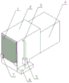
Fig. 1 is the utility model relates to a coal mining dust suppression device's three-dimensional structure chart.
Fig. 2 is the utility model relates to a coal mining dust suppression device's three-dimensional split view.
Fig. 3 is the utility model relates to a coal mining dust suppression device's schematic structure diagram.
In the attached drawings
Wherein the method comprises the following steps: air inlet grid plate 1, dust fall case 2, water pipe 3, air suction box 4, suction pump 5, suction box 6, fixed cutting ferrule 7, dust filter net 8, support frame 9, fan 10, water pipe through-hole 11, circulation mouth 12 that draws water, dust fall shower nozzle 13, draw water hole 14, water filter net 15, storage water tank 16, motor 17.
The specific implementation mode is as follows:
the utility model relates to a coal mining dust suppression device that pounces on one's own dust is realized like this: the utility model relates to a coal mining dust suppression and dust fall device, which comprises an air inlet grid plate 1, a dust fall box 2, a water pipe 3, an air suction box 4, a water suction pump 5, a water suction box 6, a fixed cutting sleeve 7, a dust filter screen 8, a support frame 9, a fan 10, a water pipe through hole 11, a circulating water suction port 12, a dust fall spray head 13, a water suction hole 14, a water filter screen 15, a water storage box 16 and a motor 17, wherein the water storage box 16 is arranged at the bottom of the dust fall box 2, the water storage box 16 is communicated with the dust fall box 2, the width of the water storage box 16 is smaller than that of the dust fall box 2, the air suction box 4 is arranged at the other side of the dust fall box 2, the air suction box 4 is communicated with the dust fall box 2, the height of the air suction box 4 is smaller than that of the dust fall box 2, one side of the air suction box 4 is an open structure, the air suction box 4, the dust fall box 2 and the water, and the air inlet groove is communicated with the dust-settling box 2, the bottom of the air inlet grid plate 1 is connected with the water storage tank 16 through two fixing clamping sleeves 7, one side of the water storage tank 16 is provided with a circulating water pumping port 12, a water filter net 15 is arranged in the circulating water pumping port 12, the water pumping tank 6 is arranged on one side of the water storage tank 16 and is correspondingly communicated with the circulating water pumping port 12, the top of the water pumping tank 6 is provided with a water pumping hole 14, a water pumping pump 5 is arranged above the water pumping tank 6, a water inlet pipe 3 of the water pumping pump 5 is communicated with the water pumping hole 14, the side surface of the dust-settling box 2 adjacent to the air inlet grid plate 1 is provided with a water pipe through hole 11, a water pipe 3 is arranged in the dust-settling box 2, one end of the water pipe 3 passes through the water pipe through hole 11 and extends downwards to be communicated with a water outlet pipe 3 of the water pumping pump 5, the other end of the water pipe 3 is arranged on the, the other end of dust filter 8 is connected with the bottom of grid tray 1 that admits air, form a dust fall chamber between dust filter 8 and the 2 tops of dust fall case, water pipe 3 overhead has a plurality of dust fall shower nozzles 13, dust fall shower nozzle 13 and water pipe 3 are linked together, just dust fall shower nozzle 13 arranges the dust fall intracavity in, and in suction box 4 was arranged in to two support frames 9, just support frame 9 and suction box 4 inner wall were connected, and motor 17 arranged in on one support frame 9, and be located between two support frames 9, and fan 10 is arranged in between two support frames 9, pivot one end and another support frame 9 rotatable coupling on the fan 10, the pivot other end on the fan 10 is connected with motor 17 axle on the motor 17, support frame 9 is Y type support frame 9, and is a plurality of dust fall shower nozzle 13's angle is different from each other.
When the dust-settling water-saving device is used, firstly, the water storage tank 16 is filled with water, then the motor 17 works, the motor 17 drives the fan 10 to rotate to form air flow, dust gas is driven to enter a dust-settling cavity in the dust-settling box 2 through the air inlet grid plate 1, meanwhile, the water suction pump 5 starts to work, water in the water storage tank 16 is pumped out from the circulating water pumping port 12 under the action of pumping force, when the water passes through the circulating water pumping port 12, the water is filtered through the water filtering net 15 and enters the water pumping box 6, then flows into the water pipe 3 through the water suction pump 5 and is sprayed out from the dust-settling nozzles 13 to form water mist, the dust gas in the dust-settling cavity is sprayed and settled, the sprayed water mist is filtered through the dust filtering net 8 and then falls into the water storage tank, the fan drives the air flow to flow, the air flow passes through the inclined dust filtering net 8, other part of dust is filtered in the air flow process, the dust-settled gas is, the water is pumped out continuously under the pressure of the water pump 5 again, and dust carried by the water is filtered by the water filtering net 15 and recycled when the water passes through the circulating water outlet;
the support frame 9 is designed to be of a Y-shaped structure, and can form a triangular structure with the inner wall of the air pumping box 4, so that the support is firmer;
the design that the angles of the dust fall spray heads 13 are different from each other enables the spraying directions of the sprayed water mist to be different during spraying, the spraying coverage range is increased, and the spraying dust fall effect is improved;
the purposes of actively sucking dust through the fan 10 and performing spraying dust reduction by matching with circulating water are achieved.
The above embodiments are the preferred embodiments of the present invention, and are not intended to limit the scope of the present invention. Any person skilled in the art can make some modifications without departing from the scope of the invention, i.e. all equivalent modifications made according to the invention are intended to be covered by the scope of the invention.
Claims (6)
1. The utility model provides a coal mining dust suppression device that pounces on one's own dust, characterized by: the dust-falling dust-collecting device comprises an air inlet grid plate, a dust-falling box, a water pipe, an air suction box, a water suction pump, a water suction box, a fixed clamping sleeve, a dust-filtering net, a support frame, a fan, a water pipe through hole, a circulating water suction opening, a dust-falling spray head, a water suction hole, a water filtering net, a water storage box and a motor, wherein the water storage box is arranged at the bottom of the dust-falling box, the water storage box is communicated with the dust-falling box, the air suction box is arranged at the other side of the dust-falling box, the air suction box is communicated with the dust-falling box, one side of the air suction box is of an open structure, the air inlet grid plate is arranged at one side of the dust-falling box, a plurality of air inlet grooves are formed on the air inlet grid plate at equal intervals and are communicated with the dust-falling box, the bottom of the air inlet grid, the top of suction box is opened there is the drinking-water hole, and the suction pump is arranged in the suction box top, just the inlet tube and the drinking-water hole of suction pump are linked together, it has the water pipe through-hole to open on the side of the adjacent grid tray that admits air of dust box, and the water pipe is arranged in the dust box, the water pipe through-hole is passed to the one end of water pipe, and downwardly extending and the outlet pipe of suction pump are linked together, on the inner wall of dust box was arranged in to the other end of water pipe, the dust screen was arranged in the dust box, the one end and the dust screen top of dust screen were connected, the other end and the bottom of the grid tray that admits air of dust screen are connected, form a dust fall chamber between dust screen and the dust screen top, the water pipe is overhead has a plurality of dust fall shower nozzles, dust fall shower nozzle and water pipe are linked together, just the dust fall shower nozzle is arranged in, the motor is arranged on one support frame and is positioned between the two support frames, the fan is arranged between the two support frames, one end of a rotating shaft on the fan is connected with the other support frame, and the other end of the rotating shaft on the fan is connected with a motor shaft on the motor.
2. The coal mining dust suppression device according to claim 1, wherein the angles of the dust suppression nozzles are different from each other.
3. A coal mining dust suppression and falling device according to claim 1, wherein the width of the water storage tank is smaller than the width of the dust suppression tank.
4. A coal mining dust suppression and falling device according to claim 1, wherein the height of the air suction box is less than the height of the dust suppression box.
5. A coal mining dust suppression and falling device according to claim 4, wherein the air suction box, the dust suppression box and the water storage tank are integrally formed.
6. The coal mining dust suppression and falling device according to claim 1, wherein the support frame is a Y-shaped support frame.
Priority Applications (1)
| Application Number | Priority Date | Filing Date | Title |
|---|---|---|---|
| CN202020464168.9U CN211987798U (en) | 2020-04-02 | 2020-04-02 | Dust suppression device for coal mining |
Applications Claiming Priority (1)
| Application Number | Priority Date | Filing Date | Title |
|---|---|---|---|
| CN202020464168.9U CN211987798U (en) | 2020-04-02 | 2020-04-02 | Dust suppression device for coal mining |
Publications (1)
| Publication Number | Publication Date |
|---|---|
| CN211987798U true CN211987798U (en) | 2020-11-24 |
Family
ID=73403626
Family Applications (1)
| Application Number | Title | Priority Date | Filing Date |
|---|---|---|---|
| CN202020464168.9U Expired - Fee Related CN211987798U (en) | 2020-04-02 | 2020-04-02 | Dust suppression device for coal mining |
Country Status (1)
| Country | Link |
|---|---|
| CN (1) | CN211987798U (en) |
Cited By (1)
| Publication number | Priority date | Publication date | Assignee | Title |
|---|---|---|---|---|
| CN112879075A (en) * | 2021-01-14 | 2021-06-01 | 赵海妮 | Dust-settling device for coal mine excavation propulsion |
-
2020
- 2020-04-02 CN CN202020464168.9U patent/CN211987798U/en not_active Expired - Fee Related
Cited By (2)
| Publication number | Priority date | Publication date | Assignee | Title |
|---|---|---|---|---|
| CN112879075A (en) * | 2021-01-14 | 2021-06-01 | 赵海妮 | Dust-settling device for coal mine excavation propulsion |
| CN112879075B (en) * | 2021-01-14 | 2024-02-23 | 赵海妮 | Dust fall device for coal mine excavation propulsion |
Similar Documents
| Publication | Publication Date | Title |
|---|---|---|
| CN211818057U (en) | Spray cooling and dust settling equipment for building construction | |
| CN211987798U (en) | Dust suppression device for coal mining | |
| CN114288796B (en) | Environment-friendly construction dust fall equipment | |
| CN104747227A (en) | Net type foam film dust removal system for underground coal mine | |
| CN213193001U (en) | Building site environment improvement device for engineering management | |
| CN206188757U (en) | Wet -type gas dust disposal ware | |
| CN211753459U (en) | Efficient and energy-saving dust settling device for building construction | |
| CN210993360U (en) | Efficient dust collector | |
| CN210699320U (en) | Dust collecting equipment for building construction site is built in room | |
| CN115805224A (en) | Dust extraction is used in construction is decorated to indoor building | |
| CN213392150U (en) | Dust fall tool for coal mining tunneling machine | |
| CN215505984U (en) | Pulse dust collector is used in processing of gypsum building block | |
| CN214811710U (en) | Green energy-concerving and environment-protective sprinkler for construction | |
| CN110478997B (en) | Industrial dust collector | |
| CN218030270U (en) | Ventilation and dust removal device for coal mine operation | |
| CN215138076U (en) | Water type dust treatment equipment | |
| CN220779587U (en) | Raise dust processing apparatus for building engineering | |
| CN218077125U (en) | Punching and dust removing device for building fire fighting construction | |
| CN219647049U (en) | Water-saving dust settling device | |
| CN213627654U (en) | A ventilation dust device for tunnel entrance to a cave | |
| CN217129585U (en) | Wet-type down-the-hole gas drainage device for coal mine | |
| CN212985276U (en) | Coal mine spraying dust-settling equipment | |
| CN219185971U (en) | Intelligent unitized sewage treatment device | |
| CN218774518U (en) | Intelligent spraying device of building construction site | |
| CN216259780U (en) | Dust collector for housing construction |
Legal Events
| Date | Code | Title | Description |
|---|---|---|---|
| GR01 | Patent grant | ||
| GR01 | Patent grant | ||
| CF01 | Termination of patent right due to non-payment of annual fee |
Granted publication date: 20201124 |