CN211970647U - Material conveying mechanism with fixing structure for machining - Google Patents
Material conveying mechanism with fixing structure for machining Download PDFInfo
- Publication number
- CN211970647U CN211970647U CN202020468964.XU CN202020468964U CN211970647U CN 211970647 U CN211970647 U CN 211970647U CN 202020468964 U CN202020468964 U CN 202020468964U CN 211970647 U CN211970647 U CN 211970647U
- Authority
- CN
- China
- Prior art keywords
- plate
- conveyer belt
- motor
- machining
- installs
- Prior art date
- Legal status (The legal status is an assumption and is not a legal conclusion. Google has not performed a legal analysis and makes no representation as to the accuracy of the status listed.)
- Expired - Fee Related
Links
- 238000003754 machining Methods 0.000 title claims abstract description 23
- 239000000463 material Substances 0.000 title claims abstract description 11
- 238000000034 method Methods 0.000 abstract description 3
- 230000008602 contraction Effects 0.000 description 2
- 230000000694 effects Effects 0.000 description 2
- 239000000178 monomer Substances 0.000 description 2
- XLYOFNOQVPJJNP-UHFFFAOYSA-N water Substances O XLYOFNOQVPJJNP-UHFFFAOYSA-N 0.000 description 2
- 206010066054 Dysmorphism Diseases 0.000 description 1
- 230000009286 beneficial effect Effects 0.000 description 1
- 238000012986 modification Methods 0.000 description 1
- 230000004048 modification Effects 0.000 description 1
- 230000000149 penetrating effect Effects 0.000 description 1
- 238000003466 welding Methods 0.000 description 1
Images


Abstract
The utility model discloses a machining is with defeated material mechanism with fixed knot constructs, including conveyer belt, first motor and horizontal pole, the gyro wheel is installed to the inboard of conveyer belt, and the outside of gyro wheel installs the support frame, the operation panel is installed to the left end of conveyer belt, and the rear side of second gear installs the second motor, the connecting rod is installed in the left side of backup pad, and the end-to-end connection of connecting rod has the spring, the grip block is installed to the top of backup pad, and the inside of grip block runs through and installs the gag lever post, the end-to-end connection of gag lever post has the third motor, the diaphragm is installed to the bottom of conveyer belt, and the internally mounted of diaphragm has the supporting shoe, electric telescopic handle is installed to the bottom of supporting shoe, and electric telescopic handle. This defeated material mechanism is used in machining with fixed knot constructs can not only fix the part after the conveying, conveniently takes out the part that processes moreover.
Description
Technical Field
The utility model relates to a machining technical field specifically is a machining is with defeated material mechanism with fixed knot constructs.
Background
Need carry the part among the machining process, conveniently process the part, current defeated material mechanism is the conveyer belt usually, places the part on the conveyer belt, through the removal of conveyer belt and then accomplish the transport to the part.
At present, a commonly-used conveying mechanism for machining cannot fix a conveyed part and is inconvenient to take out the machined part, so that the conveying mechanism with the fixing structure for machining is provided, and the problems in the prior art are solved.
SUMMERY OF THE UTILITY MODEL
An object of the utility model is to provide a machining is with defeated material mechanism with fixed knot constructs to solve the present machining commonly used that above-mentioned background art provided and with defeated material mechanism, can not fix the part after the conveying, and the inconvenient problem that the part that will process takes out.
In order to achieve the above object, the utility model provides a following technical scheme: a feeding mechanism with a fixed structure for machining comprises a conveying belt, a first motor and a cross rod, wherein rollers are installed on the inner side of the conveying belt, a support frame is installed on the outer side of each roller, the first motor is installed at the left side position of the conveying belt, baffles are installed at the front end and the rear end of the upper surface of the conveying belt, the cross rod is fixedly installed at the outer surface position of each baffle, a fixing frame is installed on the outer side of each baffle, a stop lever is installed on the upper surface of the fixing frame, a first gear is installed on the inner side of each stop lever, a limiting plate is installed on the front side of each stop lever, an operating table is installed at the left end of the conveying belt, a supporting plate is installed at the middle position of the conveying belt, a second gear is connected to the right side of the bottom of the supporting plate, a second motor is installed on the rear side of, the clamp plate is installed to the top of backup pad, and the inside of clamp plate runs through and installs the gag lever post, the end-to-end connection of gag lever post has the third motor, the diaphragm is installed to the bottom of conveyer belt, and the internally mounted of diaphragm has the supporting shoe, electric telescopic handle is installed to the bottom of supporting shoe, and electric telescopic handle's bottom installs the fixed plate.
Preferably, the conveying belt is obliquely arranged on the left side of the operating platform, and a rotating structure is formed between the conveying belt and the fixing plate.
Preferably, the bottom of the supporting plate is provided with a sawtooth structure, and a lifting structure is formed between the supporting plate and the operating platform.
Preferably, the vertical section of the clamping plate is in a convex structure, and the clamping plate is arranged at the outer side of the supporting plate.
Preferably, the front end and the rear end of the outer surface of the limiting rod are thread-shaped structures with opposite directions, and a linkage structure is formed between the limiting rod and the clamping plate.
Preferably, the supporting block is connected with the electric telescopic rod in a hinged mode, and a left-right sliding structure is formed between the supporting block and the transverse plate.
Compared with the prior art, the beneficial effects of the utility model are that: the material conveying mechanism with the fixing structure for machining not only can fix the conveyed parts, but also is convenient for taking out the machined parts;
1. the outer surface of the limiting rod is of a threaded structure, the clamping plate can move through a linkage structure formed between the limiting rod and the clamping plate, the part can be fixed through the movement of the clamping plate, and the connecting rod can be tightly attached to the outer surface of the part through the extension and retraction of the spring;
2. after the machining is finished, the clamping plate is moved outwards, the supporting plate can be moved upwards through the meshing between the supporting plate and the second gear, and the height of the supporting plate exceeds the position of the clamping plate, so that the machined part can be taken out conveniently;
3. through the linkage structure that constitutes between first gear, shelves pole and the limiting plate for the limiting plate removes, is convenient for adjust the distance between the limiting plate monomer, can play the effect of water conservancy diversion to the part through the limiting plate, and both ends all take over around the conveyer belt and install the baffle, and through horizontal pole and bolt fixed mounting on the support frame, be convenient for take off the baffle from the conveyer belt, can wash the surface of conveyer belt.
Drawings
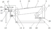
FIG. 1 is a schematic view of the overlooking and sectioning structure of the present invention;
FIG. 2 is a front view of the cutting structure of the present invention;
FIG. 3 is a schematic view of a side view of the connection between the conveyor belt and the baffle plate of the present invention;
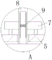
fig. 4 is an enlarged schematic structural view of a portion a in fig. 1 according to the present invention.
In the figure: 1. a conveyor belt; 2. a roller; 3. a support frame; 4. a first motor; 5. a baffle plate; 6. a cross bar; 7. a fixed mount; 8. a gear lever; 9. a first gear; 10. a limiting plate; 11. an operation table; 12. a support plate; 13. a second gear; 14. a second motor; 15. a connecting rod; 16. a spring; 17. a clamping plate; 18. a limiting rod; 19. a third motor; 20. a transverse plate; 21. a support block; 22. an electric telescopic rod; 23. and (7) fixing the plate.
Detailed Description
The technical solutions in the embodiments of the present invention will be described clearly and completely with reference to the accompanying drawings in the embodiments of the present invention, and it is obvious that the described embodiments are only some embodiments of the present invention, not all embodiments. Based on the embodiments in the present invention, all other embodiments obtained by a person skilled in the art without creative work belong to the protection scope of the present invention.
Referring to fig. 1-4, the present invention provides a technical solution: a feeding mechanism with a fixed structure for machining comprises a conveying belt 1, rollers 2, a support frame 3, a first motor 4, a baffle 5, a cross rod 6, a fixing frame 7, a stop rod 8, a first gear 9, a limiting plate 10, an operating platform 11, a support plate 12, a second gear 13, a second motor 14, a connecting rod 15, a spring 16, a clamping plate 17, a limiting rod 18, a third motor 19, a transverse plate 20, a supporting block 21, an electric telescopic rod 22 and a fixing plate 23, wherein the rollers 2 are installed on the inner side of the conveying belt 1, the support frame 3 is installed on the outer side of the rollers 2, the first motor 4 is installed at the left side position of the conveying belt 1, the baffles 5 are installed at the front end and the rear end of the upper surface of the conveying belt 1, the cross rod 6 is fixedly installed at the outer surface position of the baffles 5, the fixing frame 7 is installed on the outer side of the fixing frame 7, the stop rod 8 is installed on the, a limit plate 10 is installed at the front side of the stop lever 8, an operation table 11 is installed at the left end of the conveyor belt 1, a support plate 12 is installed at the middle position of the conveyor belt 1, the conveyor belt 1 is obliquely arranged at the left side of the operation table 11, a rotating structure is formed between the conveyor belt 1 and a fixing plate 23 to facilitate the adjustment of the angle of the conveyor belt 1, a zigzag structure is arranged at the bottom of the support plate 12, a lifting structure is formed between the support plate 12 and the operation table 11 to facilitate the lifting of the support plate 12, a second gear 13 is connected to the right side of the bottom of the support plate 12, a second motor 14 is installed at the rear side of the second gear 13, a connecting rod 15 is installed at the left side of the support plate 12, a spring 16 is connected to the tail end of the connecting rod 15, a clamping plate 17 is installed above the support plate 12, a limit lever 18 is installed in the clamping plate 17 in a penetrating, the holding plate 17 can be fixed the part, and the end connection of gag lever post 18 has third motor 19, and diaphragm 20 is installed to the bottom of conveyer belt 1, and the internally mounted of diaphragm 20 has supporting shoe 21, and electric telescopic handle 22 is installed to the bottom of supporting shoe 21, and fixed plate 23 is installed to electric telescopic handle 22's bottom.
As shown in fig. 2, the front end and the rear end of the outer surface of the limiting rod 18 are thread structures with opposite directions, and an interlocking structure is formed between the limiting rod 18 and the clamping plate 17, and the rotation of the limiting rod 18 drives the clamping plate 17 to move.
As shown in fig. 2, the supporting block 21 and the electric telescopic rod 22 are connected in an articulated manner, and a left-right sliding structure is formed between the supporting block 21 and the transverse plate 20, and the electric telescopic rod 22 drives the supporting block 21 to slide inside the transverse plate 20.
The working principle is as follows: when the feeding mechanism with the fixed structure for machining is used, mechanical parts are placed on the conveying belt 1, the first motor 4 drives the roller 2 to rotate as shown in fig. 1, the roller 2 rotates to drive the conveying belt 1 to rotate, so that the parts are conveyed, as shown in fig. 2, the transverse plate 20 is connected below the supporting frame 3, the supporting block 21 is installed inside the transverse plate 20, the bottom of the supporting block 21 is connected with the electric telescopic rod 22, the supporting block 21 and the electric telescopic rod 22 are connected in a hinged mode, a rotating structure is formed between the fixed plate 23 and the supporting frame 3, the supporting frame 3 can rotate through the expansion and contraction of the electric telescopic rod 22, the parts on the conveying belt 1 can fall on the supporting plate 12 of the operating platform 11 one by one through the interval rotation of the first motor 4, as the connecting rod 15 is attached to the left end of the supporting plate 12, the connecting rod 15 can be closely attached to the parts through the expansion and contraction of the, because the outer surface of the limiting rod 18 is in a thread structure, the limiting rod 18 is driven by the third motor 19 to rotate clockwise and anticlockwise, the clamping plate 17 can be moved by the rotation of the limiting rod 18, the part can be fixed by the movement of the clamping plate 17, the part can be processed by a processing device connected with the outside, after the processing is finished, the clamping plate 17 is moved outwards, the bottom of the supporting plate 12 is in a zigzag structure, the second motor 14 drives the second gear 13 to rotate, the supporting plate 12 can be moved upwards by the rotation of the second gear 13, and the height of the supporting plate exceeds the position of the clamping plate 17, so that the processed part can be conveniently taken out, for example, in fig. 4, the fixing frame 7 is fixedly provided with the first gear 9, the outer side of the first gear 9 is provided with the baffle rod 8, the tail end of the baffle rod 8 is fixedly provided with the limiting plate 10, the limiting plate 10 can be moved by rotating the first gear, be convenient for adjust the distance between the limiting plate 10 monomer, can play the effect of water conservancy diversion to the part through limiting plate 10, both ends are all taken around conveyer belt 1 and are installed baffle 5, and the fixed surface of baffle 5 installs horizontal pole 6, and horizontal pole 6 passes through bolt fixed mounting on support frame 3, are convenient for take off baffle 5 from conveyer belt 1, can wash the surface of conveyer belt 1, and this is exactly this machining with defeated material mechanism's that has fixed knot to construct whole course of work.
Those not described in detail in this specification are within the skill of the art. The utility model discloses the standard part that uses all can purchase from the market, and dysmorphism piece all can be customized according to the description with the record of drawing of description, and the concrete connection mode of each part all adopts conventional means such as ripe bolt, rivet, welding among the prior art, and machinery, part and equipment all adopt prior art, and conventional model, including circuit connection adopts conventional connection mode among the prior art, does not detailed here again.
Although the present invention has been described in detail with reference to the foregoing embodiments, it will be apparent to those skilled in the art that modifications may be made to the embodiments or portions thereof without departing from the spirit and scope of the invention.
Claims (6)
1. The utility model provides a machining is with defeated material mechanism with fixed knot constructs, includes conveyer belt (1), first motor (4) and horizontal pole (6), its characterized in that: gyro wheel (2) are installed to the inboard of conveyer belt (1), and support frame (3) are installed in the outside of gyro wheel (2), first motor (4) are installed in the left side position of conveyer belt (1), and baffle (5) are all installed at the upper surface front and back both ends of conveyer belt (1), horizontal pole (6) fixed mounting is in the surface position of baffle (5), and the outside of baffle (5) installs mount (7), the last surface mounting of mount (7) has shelves pole (8), and the inboard of shelves pole (8) installs first gear (9), limiting plate (10) are installed to the front side of shelves pole (8), operation panel (11) are installed to the left end of conveyer belt (1), and the intermediate position of conveyer belt (1) installs backup pad (12), the bottom right side of backup pad (12) is connected with second gear (13), and second motor (14) are installed to the rear side of second gear (13), connecting rod (15) are installed in the left side of backup pad (12), and the end-to-end connection of connecting rod (15) has spring (16), grip block (17) are installed to the top of backup pad (12), and the inside of grip block (17) runs through and installs gag lever post (18), the end-to-end connection of gag lever post (18) has third motor (19), diaphragm (20) are installed to the bottom of conveyer belt (1), and the internally mounted of diaphragm (20) has supporting shoe (21), electric telescopic handle (22) are installed to the bottom of supporting shoe (21), and fixed plate (23) are installed to the bottom of electric telescopic handle (22).
2. The feeding mechanism with fixed structure for machining according to claim 1, wherein: the conveying belt (1) is obliquely arranged on the left side of the operating platform (11), and a rotating structure is formed between the conveying belt (1) and the fixing plate (23).
3. The feeding mechanism with fixed structure for machining according to claim 1, wherein: the bottom of the supporting plate (12) is in a sawtooth structure, and a lifting structure is formed between the supporting plate (12) and the operating platform (11).
4. The feeding mechanism with fixed structure for machining according to claim 1, wherein: the vertical section of the clamping plate (17) is of a convex structure, and the clamping plate (17) is arranged at the outer side of the supporting plate (12).
5. The feeding mechanism with fixed structure for machining according to claim 1, wherein: the front end and the rear end of the outer surface of the limiting rod (18) are thread-shaped structures with opposite directions, and a linkage structure is formed between the limiting rod (18) and the clamping plate (17).
6. The feeding mechanism with fixed structure for machining according to claim 1, wherein: the supporting block (21) is hinged with the electric telescopic rod (22), and a left-right sliding structure is formed between the supporting block (21) and the transverse plate (20).
Priority Applications (1)
| Application Number | Priority Date | Filing Date | Title |
|---|---|---|---|
| CN202020468964.XU CN211970647U (en) | 2020-04-02 | 2020-04-02 | Material conveying mechanism with fixing structure for machining |
Applications Claiming Priority (1)
| Application Number | Priority Date | Filing Date | Title |
|---|---|---|---|
| CN202020468964.XU CN211970647U (en) | 2020-04-02 | 2020-04-02 | Material conveying mechanism with fixing structure for machining |
Publications (1)
| Publication Number | Publication Date |
|---|---|
| CN211970647U true CN211970647U (en) | 2020-11-20 |
Family
ID=73382189
Family Applications (1)
| Application Number | Title | Priority Date | Filing Date |
|---|---|---|---|
| CN202020468964.XU Expired - Fee Related CN211970647U (en) | 2020-04-02 | 2020-04-02 | Material conveying mechanism with fixing structure for machining |
Country Status (1)
| Country | Link |
|---|---|
| CN (1) | CN211970647U (en) |
Cited By (1)
| Publication number | Priority date | Publication date | Assignee | Title |
|---|---|---|---|---|
| CN114955488A (en) * | 2022-06-14 | 2022-08-30 | 赣州市超华科技有限公司 | Stacking device for air conditioner radiating fin production |
-
2020
- 2020-04-02 CN CN202020468964.XU patent/CN211970647U/en not_active Expired - Fee Related
Cited By (2)
| Publication number | Priority date | Publication date | Assignee | Title |
|---|---|---|---|---|
| CN114955488A (en) * | 2022-06-14 | 2022-08-30 | 赣州市超华科技有限公司 | Stacking device for air conditioner radiating fin production |
| CN114955488B (en) * | 2022-06-14 | 2023-08-08 | 赣州市超华科技有限公司 | Stacking device for air conditioner cooling fin production |
Similar Documents
| Publication | Publication Date | Title |
|---|---|---|
| CN211970647U (en) | Material conveying mechanism with fixing structure for machining | |
| CN213826807U (en) | Bar cutting device is used in pole production | |
| CN112496884B (en) | Automatic knot device that removes of log | |
| CN110884909A (en) | Feeding device for rice deep processing | |
| CN211101499U (en) | Deburring device for die casting forming machine | |
| CN209840961U (en) | Automatic boundary detection cutting equipment for plates | |
| CN211366927U (en) | Transmission mechanism of ampoule wire-drawing filling machine | |
| CN214392896U (en) | Stainless steel tubular product welding equipment | |
| CN209867073U (en) | Section bending machine capable of automatically feeding | |
| CN210394160U (en) | Outer glass tube positioning and cutting device for solar vacuum tube production | |
| CN211919990U (en) | Assembly line with heavy product automatic transfer device product | |
| CN216800787U (en) | Cleaning device for panel processing | |
| CN217229006U (en) | Automatic deviation correcting device of vacuum drying equipment | |
| CN212630425U (en) | Dustproof cloth display device for spinning | |
| CN111673170A (en) | Multi-angle dustproof cutting device for metal processing | |
| CN111889799B (en) | Multi-steel bar cutting equipment and using method thereof | |
| CN213162566U (en) | Feeding device for pipe bending machine | |
| CN211304969U (en) | Tin bar cutting device | |
| CN213105660U (en) | Clamping device of horizontal sawing machine | |
| CN110666911B (en) | A remove device that is used for outer branch of wicker | |
| CN213681453U (en) | Cutting machine is used in clothing manufacturing production | |
| CN210138883U (en) | Combined type movable high-pressure cleaning equipment | |
| CN217529200U (en) | Separator | |
| CN219429057U (en) | Plank upset processor | |
| CN219633901U (en) | Transverse cutting device for processing potato starch vermicelli |
Legal Events
| Date | Code | Title | Description |
|---|---|---|---|
| GR01 | Patent grant | ||
| GR01 | Patent grant | ||
| TR01 | Transfer of patent right | ||
| TR01 | Transfer of patent right |
Effective date of registration: 20221118 Address after: No. 2098, Freight Avenue, Southwest Airport Economic Development Zone, Shuangliu District, Chengdu, Sichuan 610000 Patentee after: Sichuan Maiyue Technology Co.,Ltd. Address before: 312500 No.136, Gantang Cunli village, Nanming street, Xinchang County, Shaoxing City, Zhejiang Province 102 Patentee before: Xinchang qiujie Machinery Technology Co.,Ltd. |
|
| CF01 | Termination of patent right due to non-payment of annual fee |
Granted publication date: 20201120 |